ECU MITSUBISHI LANCER 2005 Workshop Manual
[x] Cancel search | Manufacturer: MITSUBISHI, Model Year: 2005, Model line: LANCER, Model: MITSUBISHI LANCER 2005Pages: 788, PDF Size: 45.98 MB
Page 569 of 788
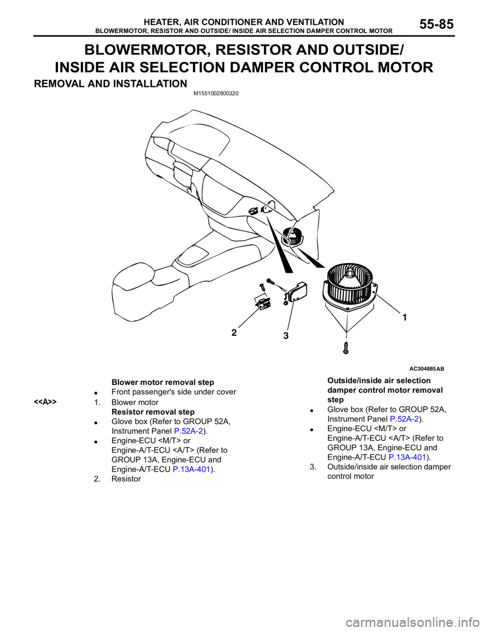
BLOWERMOTOR, RESISTOR AND OUTSIDE/ INSIDE AIR SELECTION DAMPER CONTROL MOTOR
HEATER, AIR CONDITIONER AND VENTILATION55-85
BLOWERMOTOR, RESISTOR AND OUTSIDE/
INSIDE AIR SELECTION DAMPER CONTROL MOTOR
REMOVAL AND INSTALLATION
M1551002800320
AC304885AB
2
31
Blower motor removal step
•Front passenger's side under cover
<>1. Blower motor
Resistor removal step
•Glove box (Refer to GROUP 52A,
Instrument Panel P.52A-2).
•Engine-ECU
Engine-A/T-ECU (Refer to
GROUP 13A, Engine-ECU and
Engine-A/T-ECU P.13A-401).
2. ResistorOutside/inside air selection
damper control motor removal
step
•Glove box (Refer to GROUP 52A,
Instrument Panel P.52A-2).
•Engine-ECU
Engine-A/T-ECU (Refer to
GROUP 13A, Engine-ECU and
Engine-A/T-ECU P.13A-401).
3. Outside/inside air selection damper
control motor
Page 572 of 788
EVAPORATOR ASSEMBLY
HEATER, AIR CONDITIONER AND VENTILATION55-88
EVAPORATOR ASSEMBLY
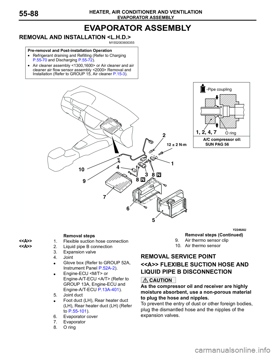
REMOVAL AND INSTALLATION
REMOVAL SERVICE POINT
<> FLEXIBLE SUCTION HOSE AND
LIQUID PIPE B DISCONNECTION
CAUTION
As the compressor oil and receiver are highly
moisture absorbent, use a non-porous material
to plug the hose and nipples.
To prevent the entry of dust or other foreign bodies,
plug the dismantled hose and the nipples of the
expansion valves.
Pre-removal and Post-installation Operation
•Refrigerant draining and Refilling (Refer to Charging
P.55-70 and Discharging P.55-72).
•Air cleaner assembly <1300,1600> or Air cleaner and air
cleaner air flow sensor assembly <2000> Removal and
Installation (Refer to GROUP 15, Air cleaner P.15-3).
Y2346AU
1, 2, 4, 7
A/C compressor oil:
SUN PAG 56O ring
-Pipe coupling
2
101
3 4
7
6
5 98
8
12 ± 2 N·m
Removal steps
<>1. Flexible suction hose connection
<>2. Liquid pipe B connection
3. Expansion valve
4. Joint
•Glove box (Refer to GROUP 52A,
Instrument Panel P.52A-2).
•Engine-ECU
Engine-A/T-ECU (Refer to
GROUP 13A, Engine-ECU and
Engine-A/T-ECU P.13A-401).
5. Joint duct
•Foot duct (LH), Rear heater duct
(LH), Rear heater duct (LH) (Refer
to P.55-101).
6. Evaporator cover
7. Evaporator
8. O ring 9. Air thermo sensor clip
10. Air thermo sensorRemoval steps (Continued)
Page 573 of 788
EVAPORATOR ASSEMBLY
HEATER, AIR CONDITIONER AND VENTILATION55-89
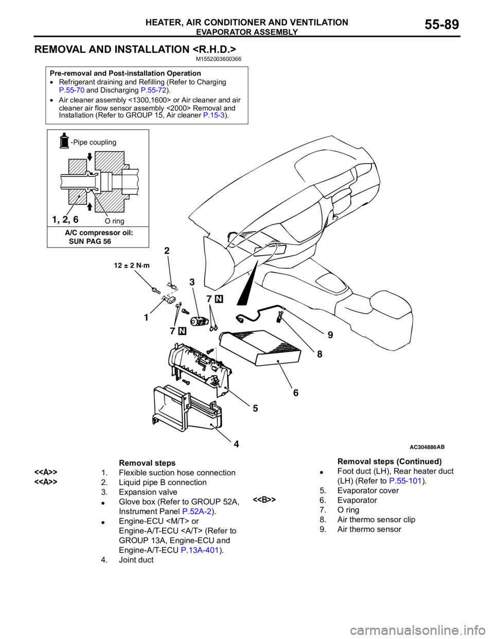
REMOVAL AND INSTALLATION
Pre-removal and Post-installation Operation
•Refrigerant draining and Refilling (Refer to Charging
P.55-70 and Discharging P.55-72).
•Air cleaner assembly <1300,1600> or Air cleaner and air
cleaner air flow sensor assembly <2000> Removal and
Installation (Refer to GROUP 15, Air cleaner P.15-3).
AC304886AB
12 ± 2 N·m
7
7
2
1
9
8
6
5
4 3 1, 2, 6
A/C compressor oil:
SUN PAG 56O ring
-Pipe coupling
Removal steps
<>1. Flexible suction hose connection
<>2. Liquid pipe B connection
3. Expansion valve
•Glove box (Refer to GROUP 52A,
Instrument Panel P.52A-2).
•Engine-ECU
Engine-A/T-ECU (Refer to
GROUP 13A, Engine-ECU and
Engine-A/T-ECU P.13A-401).
4. Joint duct•Foot duct (LH), Rear heater duct
(LH) (Refer to P.55-101).
5. Evaporator cover
<>6. Evaporator
7. O ring
8. Air thermo sensor clip
9. Air thermo sensorRemoval steps (Continued)
Page 576 of 788
Page 587 of 788
70-1
GROUP 70
COMPONENT
LOCATIONS
CONTENTS
ECU . . . . . . . . . . . . . . . . . . . . . . . . . .70-2
RELAY . . . . . . . . . . . . . . . . . . . . . . . .70-5
SENSOR. . . . . . . . . . . . . . . . . . . . . . .70-6
FUSIBLE LINK AND FUSE . . . . . . . .70-10
EARTH CABLE . . . . . . . . . . . . . . . . .70-11SOLENOID VALVE . . . . . . . . . . . . . . .70-11
DIODE . . . . . . . . . . . . . . . . . . . . . . . . .70-13
EARTH . . . . . . . . . . . . . . . . . . . . . . . .70-14
INSPECTION CONNECTOR AND
SPARE CONNECTOR . . . . . . . . . . . .70-18
Page 588 of 788
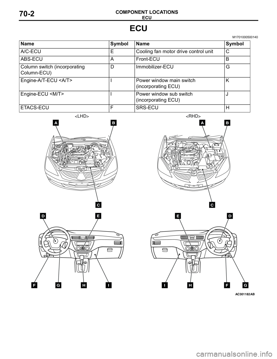
ECU
COMPONENT LOCATIONS70-2
ECU
M1701000500140
Name Symbol Name Symbol
A/C-ECU E Cooling fan motor drive control unit C
ABS-ECU A Front-ECU B
Column switch (incorporating
Column-ECU)D Immobilizer-ECU G
Engine-A/T-ECU I Power window main switch
(incorporating ECU)K
Engine-ECU
(incorporating ECU)J
ETACS-ECU F SRS-ECU H
AC301182
DE
AB
C
FGHI
AB
DE
AB
C
FGHI
Page 589 of 788
ECU
COMPONENT LOCATIONS70-3
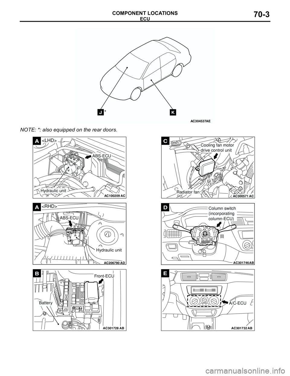
NOTE: *: also equipped on the rear doors.
AC304537
JK*
AE
AC100209AC
A
ABS-ECU
Hydraulic unit
AC206790
A
AD
ABS-ECU
Hydraulic unit
AC301728AB
BFront-ECU
Battery
AC300571
C
ACRadiator fan
Cooling fan motor
drive control unit
AC301746
DColumn switch
(incorporating
column-ECU)
AB
AC301732AB
E
A/C-ECU
Page 590 of 788
ECU
COMPONENT LOCATIONS70-4
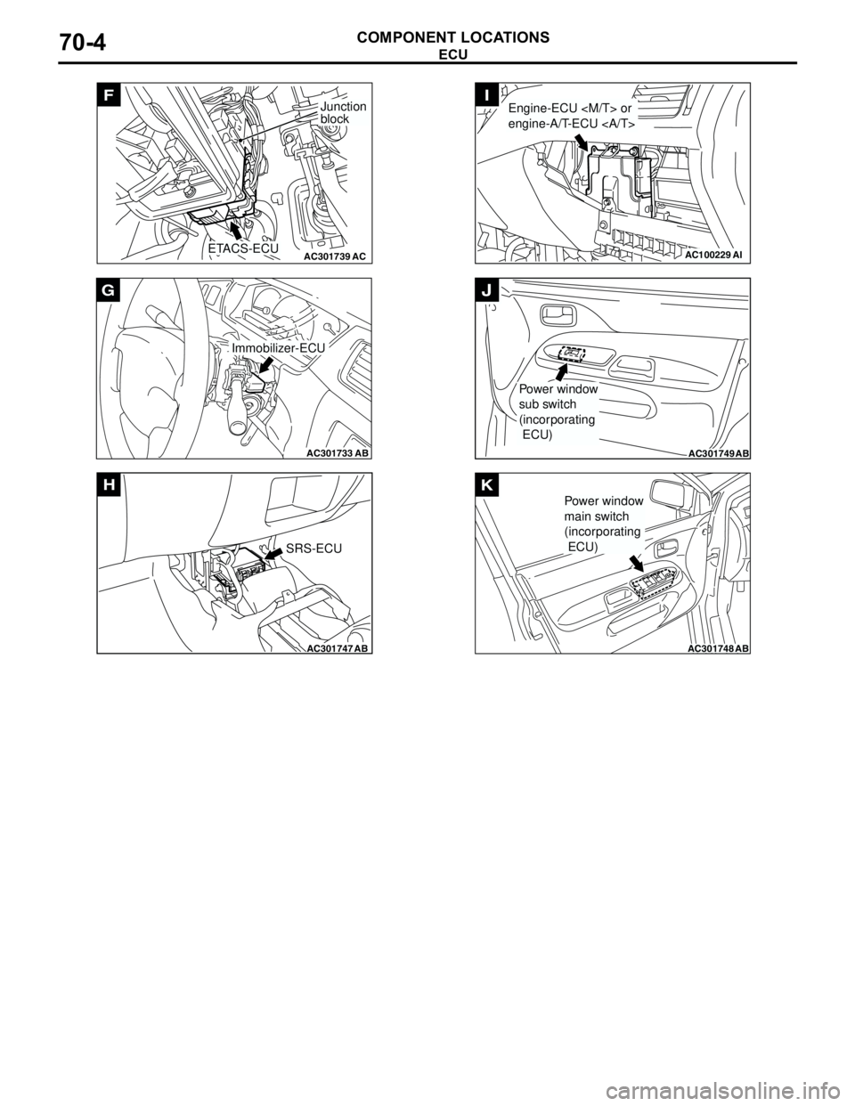
AC301739AC
F
ETACS-ECU
Junction
block
AC301733
AB
Immobilizer-ECU
G
AC301747AB
SRS-ECU
H
AC100229AI
Engine-ECU
engine-A/T-ECU I
AC301749AB
Power window
sub switch
(incorporating
ECU)
J
AC301748AB
Power window
main switch
(incorporating
ECU)
K
Page 595 of 788
Page 603 of 788
EARTH
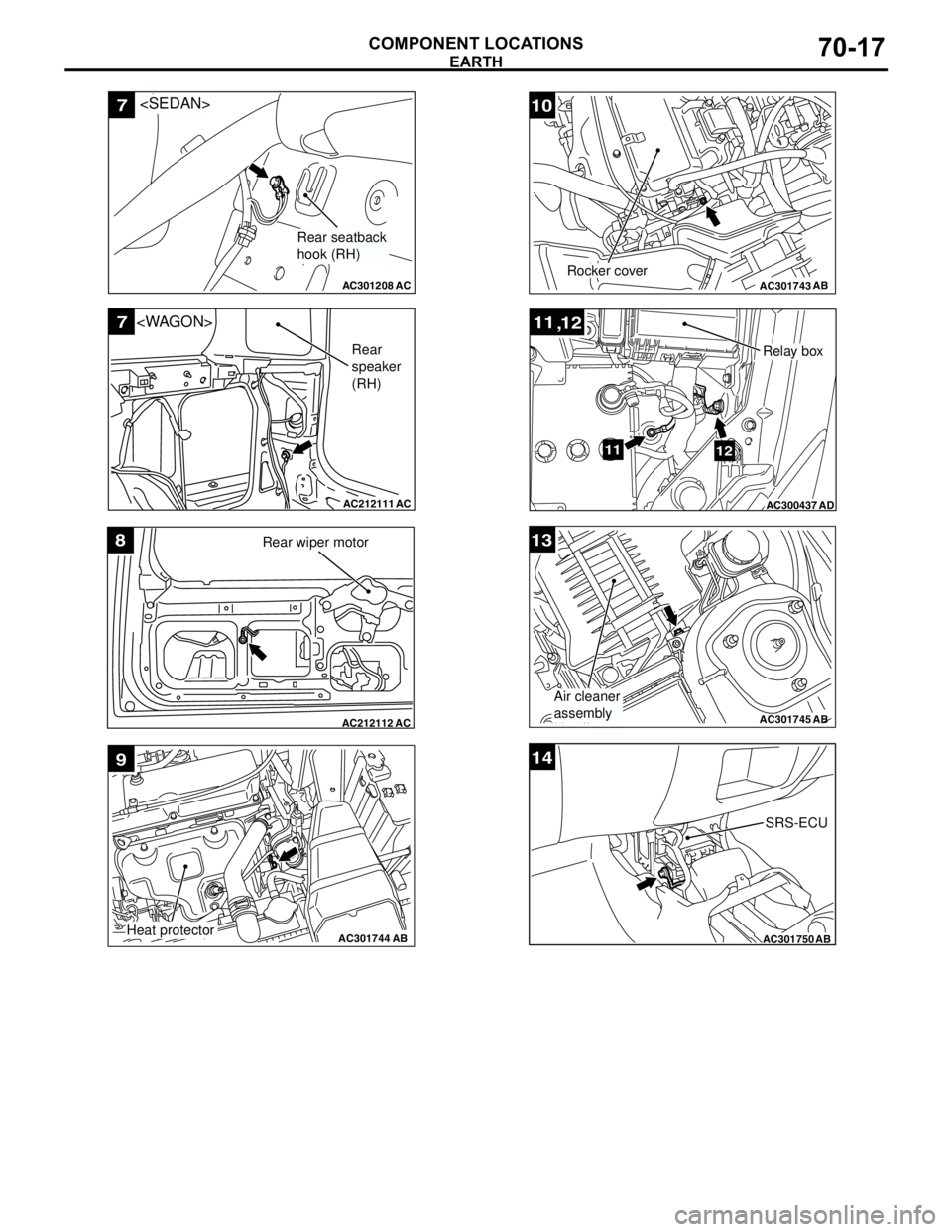
COMPONENT LOCATIONS70-17
AC301208
7
AC
Rear seatback
hook (RH)
AC212111
7
AC
Rear
speaker
(RH)
AC212112AC
8Rear wiper motor
AC301744AB
9
Heat protector
AC301743AB
10
Rocker cover
AC300437
11
12
,
1112
AD
Relay box
AC301745
13
AB
Air cleaner
assembly
AC301750AB
14
SRS-ECU