engine oil MITSUBISHI LANCER 2005 User Guide
[x] Cancel search | Manufacturer: MITSUBISHI, Model Year: 2005, Model line: LANCER, Model: MITSUBISHI LANCER 2005Pages: 788, PDF Size: 45.98 MB
Page 50 of 788
RADIATOR
ENGINE COOLING14-36
AC303473
18 171520 12
9
14
5 2
9
3
4
1
10
6 10
12 ± 2 N·m
AB
12 ± 2 N·m<4G1 (Vehicles with A/C)>
16
19
8
11
7
AC303474
18 1715
20 12 9
14
5 2
9
3
4
1
10
6 10
12 ± 2 N·m
AB
<4G6>
13
7
12 ± 2 N·m
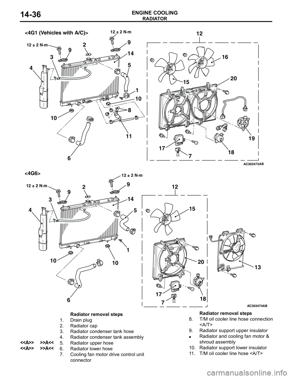
Radiator removal steps
1. Drain plug
2. Radiator cap
3. Radiator condenser tank hose
4. Radiator condenser tank assembly
<> >>A<<5. Radiator upper hose
<> >>A<<6. Radiator lower hose
7. Cooling fan motor drive control unit
connector8. T/M oil cooler line hose connection
9. Radiator support upper insulator
•Radiator and cooling fan motor &
shroud assembly
10. Radiator support lower insulator
11. T/M oil cooler line hose Radiator removal steps
Page 58 of 788
INLET MANIFOLD
INTAKE AND EXHAUST15-6
REMOVAL AND INSTALLATION <4G6>M1151003001236
Pre-removal Operation
•Fuel Line Pressure Reduction (Refer to GROUP 13A -
On-vehicle Service P.13A-389).
•Engine Coolant Draining (Refer to GROUP 14 -
On-vehicle Service P.14-22).
•Strut Tower Bar Removal (Refer to GROUP 42 P.42-9).
•Throttle Body Assembly Removal (Refer to GROUP 13B
P.13B-336).
•Fuel Delivery Pipe and Fuel Injector Assembly Removal
(Refer to GROUP 13B P.13B-334).Post-installation Operation
•Fuel Delivery Pipe and Fuel Injector Assembly Installation
(Refer to GROUP 13B P.13B-334).
•Throttle Body Assembly Installation (Refer to GROUP
13B P.13B-336).
•Strut Tower Bar Installation (Refer to GROUP 42 P.42-9).
•Engine Coolant Supplying (Refer to GROUP 14 -
On-vehicle Service P.14-22).
•Accelerator Cable Adjustment (Refer to GROUP 17 -
On-vehicle Service P.17-2).
•Fuel Leak Check
AC303657
9.0 ± 1.0 N·m11 ± 1 N·m
20 ± 2 N·m
31 ± 3 N·m 36 ± 6 N·m
20 ± 2 N·m
20 ± 2 N·m
36 ± 6 N·m
36 ± 6 N·m
11
9 10 212
N1413N
AB
5.0 ± 1.0 N·m
3
1
11 ± 1 N·m
4
N
13 ± 1 N·m
5
6
(Engine oil)
7
8
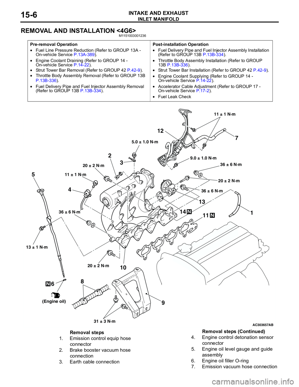
Removal steps
1. Emission control equip hose
connector
2. Brake booster vacuum hose
connection
3. Earth cable connection4. Engine control detonation sensor
connector
5. Engine oil level gauge and guide
assembly
6. Engine oil filler O-ring
7. Emission vacuum hose connectionRemoval steps (Continued)
Page 59 of 788
EXHAUST MANIFOLD
INTAKE AND EXHAUST15-7
INSPECTIONM1151003100616
Check the following points; replace the part if a
problem is found.
Inlet Manifold Check
1. Check for damage or cracking of any part.2. Clogging of the negative pressure (vacuum) outlet
port, or clogging of the exhaust gas recirculation
passages.
3. Using a straight edge and feeler gauge, check for
distortion of the cylinder head installation surface.
Standard value: 0.15 mm or less
Limit: 0.20 mm
EXHAUST MANIFOLD
REMOVAL AND INSTALLATION <4G1>M1151003300568
8. Battery wiring harness clamp
9. Inlet manifold stay
10. Inlet manifold
11. Inlet manifold gasket
12. Emission vacuum hose & pipe and
emission solenoid valve assembly
13. EGR valve
14. EGR valve gasketRemoval steps (Continued)
AC30366250 ± 10 N·m 24 ± 4 N·m
35 ± 6 N·m17 ± 2 N·m 29 ± 3 N·m
N
3
7
12 4
N
6
8
44 ± 5 N·m
AB
9
5N
29 ± 3 N·m
29 ± 3 N·m
29 ± 3 N·m
(Engine oil)
Page 60 of 788
EXHAUST MANIFOLD
INTAKE AND EXHAUST15-8
REMOVAL SERVICE POINT
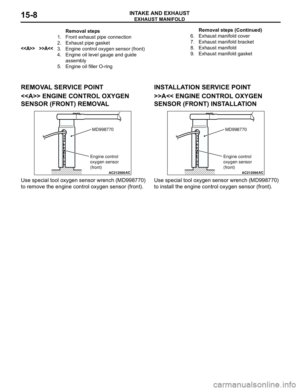
<> ENGINE CONTROL OXYGEN
SENSOR (FRONT) REMOVAL
Use special tool oxygen sensor wrench (MD998770)
to remove the engine control oxygen sensor (front).
INSTALLATION SERVICE POINT
>>A<< ENGINE CONTROL OXYGEN
SENSOR (FRONT) INSTALLATION
Use special tool oxygen sensor wrench (MD998770)
to install the engine control oxygen sensor (front).
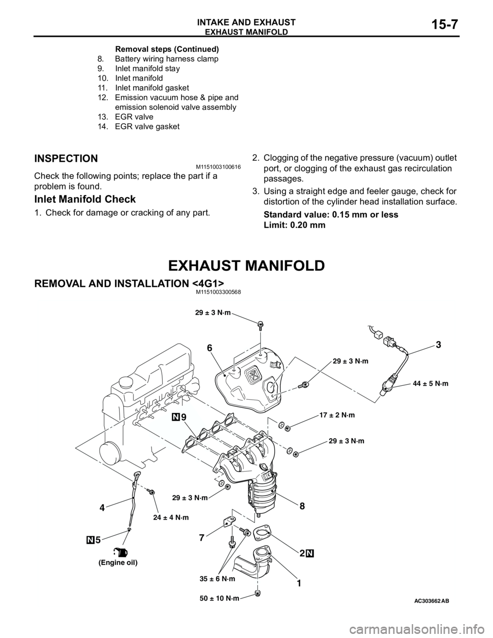
Removal steps
1. Front exhaust pipe connection
2. Exhaust pipe gasket
<> >>A<<3. Engine control oxygen sensor (front)
4. Engine oil level gauge and guide
assembly
5. Engine oil filler O-ring6. Exhaust manifold cover
7. Exhaust manifold bracket
8. Exhaust manifold
9. Exhaust manifold gasketRemoval steps (Continued)
AC212566AC
MD998770
Engine control
oxygen sensor
(front)
AC212566AC
MD998770
Engine control
oxygen sensor
(front)
Page 65 of 788
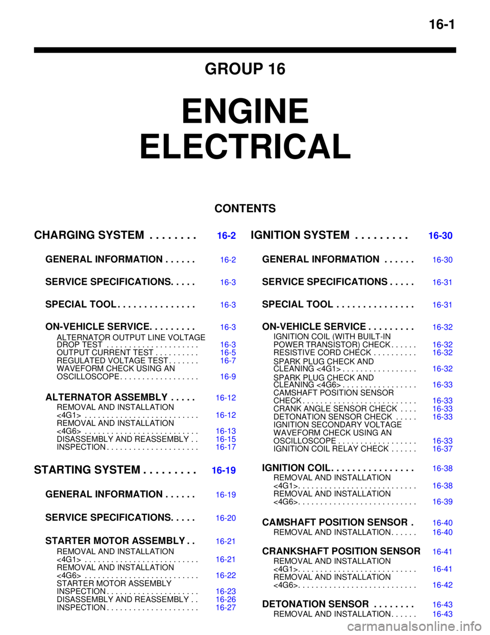
16-1
GROUP 16
ENGINE
ELECTRICAL
CONTENTS
CHARGING SYSTEM . . . . . . . .
16-2
GENERAL INFORMATION . . . . . .
16-2
SERVICE SPECIFICATIONS. . . . .16-3
SPECIAL TOOL . . . . . . . . . . . . . . .16-3
ON-VEHICLE SERVICE. . . . . . . . .16-3
ALTERNATOR OUTPUT LINE VOLTAGE
DROP TEST . . . . . . . . . . . . . . . . . . . . . 16-3
OUTPUT CURRENT TEST . . . . . . . . . . 16-5
REGULATED VOLTAGE TEST . . . . . . . 16-7
WAVEFORM CHECK USING AN
OSCILLOSCOPE . . . . . . . . . . . . . . . . . . 16-9
ALTERNATOR ASSEMBLY . . . . .16-12
REMOVAL AND INSTALLATION
<4G1> . . . . . . . . . . . . . . . . . . . . . . . . . . 16-12
REMOVAL AND INSTALLATION
<4G6> . . . . . . . . . . . . . . . . . . . . . . . . . . 16-13
DISASSEMBLY AND REASSEMBLY . . 16-15
INSPECTION . . . . . . . . . . . . . . . . . . . . . 16-17
STARTING SYSTEM . . . . . . . . .16-19
GENERAL INFORMATION . . . . . .
16-19
SERVICE SPECIFICATIONS. . . . .16-20
STARTER MOTOR ASSEMBLY . .16-21
REMOVAL AND INSTALLATION
<4G1> . . . . . . . . . . . . . . . . . . . . . . . . . . 16-21
REMOVAL AND INSTALLATION
<4G6> . . . . . . . . . . . . . . . . . . . . . . . . . . 16-22
STARTER MOTOR ASSEMBLY
INSPECTION . . . . . . . . . . . . . . . . . . . . . 16-23
DISASSEMBLY AND REASSEMBLY . . 16-26
INSPECTION . . . . . . . . . . . . . . . . . . . . . 16-27
IGNITION SYSTEM . . . . . . . . . 16-30
GENERAL INFORMATION . . . . . .
16-30
SERVICE SPECIFICATIONS . . . . .16-31
SPECIAL TOOL . . . . . . . . . . . . . . .16-31
ON-VEHICLE SERVICE . . . . . . . . .16-32
IGNITION COIL (WITH BUILT-IN
POWER TRANSISTOR) CHECK . . . . . . 16-32
RESISTIVE CORD CHECK . . . . . . . . . . 16-32
SPARK PLUG CHECK AND
CLEANING <4G1> . . . . . . . . . . . . . . . . . 16-32
SPARK PLUG CHECK AND
CLEANING <4G6> . . . . . . . . . . . . . . . . . 16-33
CAMSHAFT POSITION SENSOR
CHECK . . . . . . . . . . . . . . . . . . . . . . . . . . 16-33
CRANK ANGLE SENSOR CHECK . . . . 16-33
DETONATION SENSOR CHECK . . . . . 16-33
IGNITION SECONDARY VOLTAGE
WAVEFORM CHECK USING AN
OSCILLOSCOPE . . . . . . . . . . . . . . . . . . 16-33
IGNITION COIL RELAY CHECK . . . . . . 16-37
IGNITION COIL . . . . . . . . . . . . . . . .16-38
REMOVAL AND INSTALLATION
<4G1>. . . . . . . . . . . . . . . . . . . . . . . . . . . 16-38
REMOVAL AND INSTALLATION
<4G6>. . . . . . . . . . . . . . . . . . . . . . . . . . . 16-39
CAMSHAFT POSITION SENSOR .16-40
REMOVAL AND INSTALLATION . . . . . . 16-40
CRANKSHAFT POSITION SENSOR16-41
REMOVAL AND INSTALLATION
<4G1>. . . . . . . . . . . . . . . . . . . . . . . . . . . 16-41
REMOVAL AND INSTALLATION
<4G6>. . . . . . . . . . . . . . . . . . . . . . . . . . . 16-42
DETONATION SENSOR . . . . . . . .16-43
REMOVAL AND INSTALLATION . . . . . . 16-43
Page 66 of 788
CHARGING SYSTEM
ENGINE ELECTRICAL16-2
CHARGING SYSTEM
GENERAL INFORMATIONM1161000100522
The charging system uses the alternator output to
keep the battery charged at a constant level under
various electrical loads.
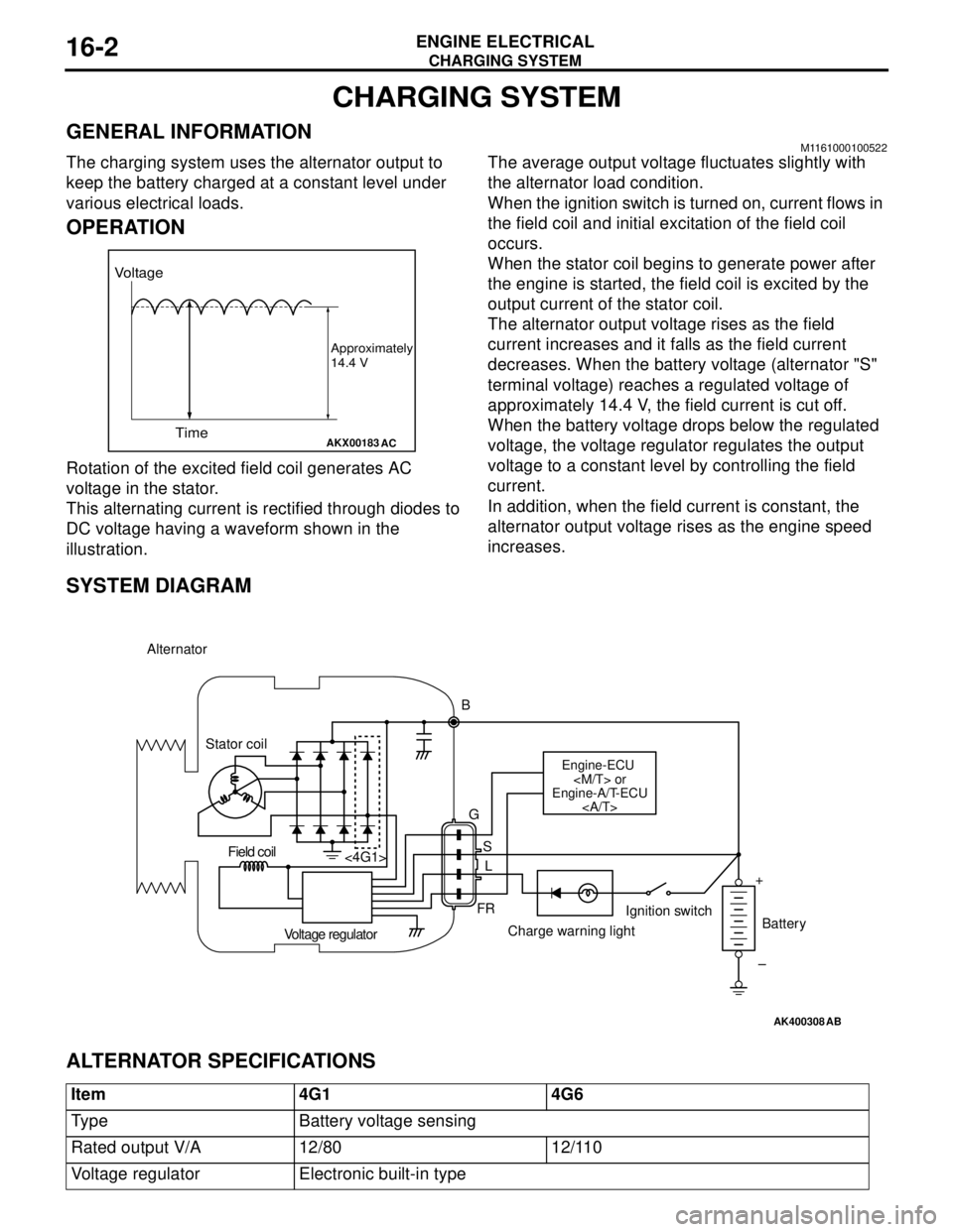
OPERATION
Rotation of the excited field coil generates AC
voltage in the stator.
This alternating current is rectified through diodes to
DC voltage having a waveform shown in the
illustration.The average output voltage fluctuates slightly with
the alternator load condition.
When the ignition switch is turned on, current flows in
the field coil and initial excitation of the field coil
occurs.
When the stator coil begins to generate power after
the engine is started, the field coil is excited by the
output current of the stator coil.
The alternator output voltage rises as the field
current increases and it falls as the field current
decreases. When the battery voltage (alternator "S"
terminal voltage) reaches a regulated voltage of
approximately 14.4 V, the field current is cut off.
When the battery voltage drops below the regulated
voltage, the voltage regulator regulates the output
voltage to a constant level by controlling the field
current.
In addition, when the field current is constant, the
alternator output voltage rises as the engine speed
increases.
SYSTEM DIAGRAM
ALTERNATOR SPECIFICATIONS
AKX00183
Voltage
Time
Approximately
14.4 V
AC
AK400308
Alternator
B
Stator coil
Engine-ECU
Engine-A/T-ECU
G
S
L
FR <4G1>
Voltage regulatorCharge warning lightIgnition switch
Battery Field coil
+
–
AB
Item 4G1 4G6
Type Battery voltage sensing
Rated output V/A 12/80 12/110
Voltage regulator Electronic built-in type
Page 75 of 788
CHARGING SYSTEM
ENGINE ELECTRICAL16-11
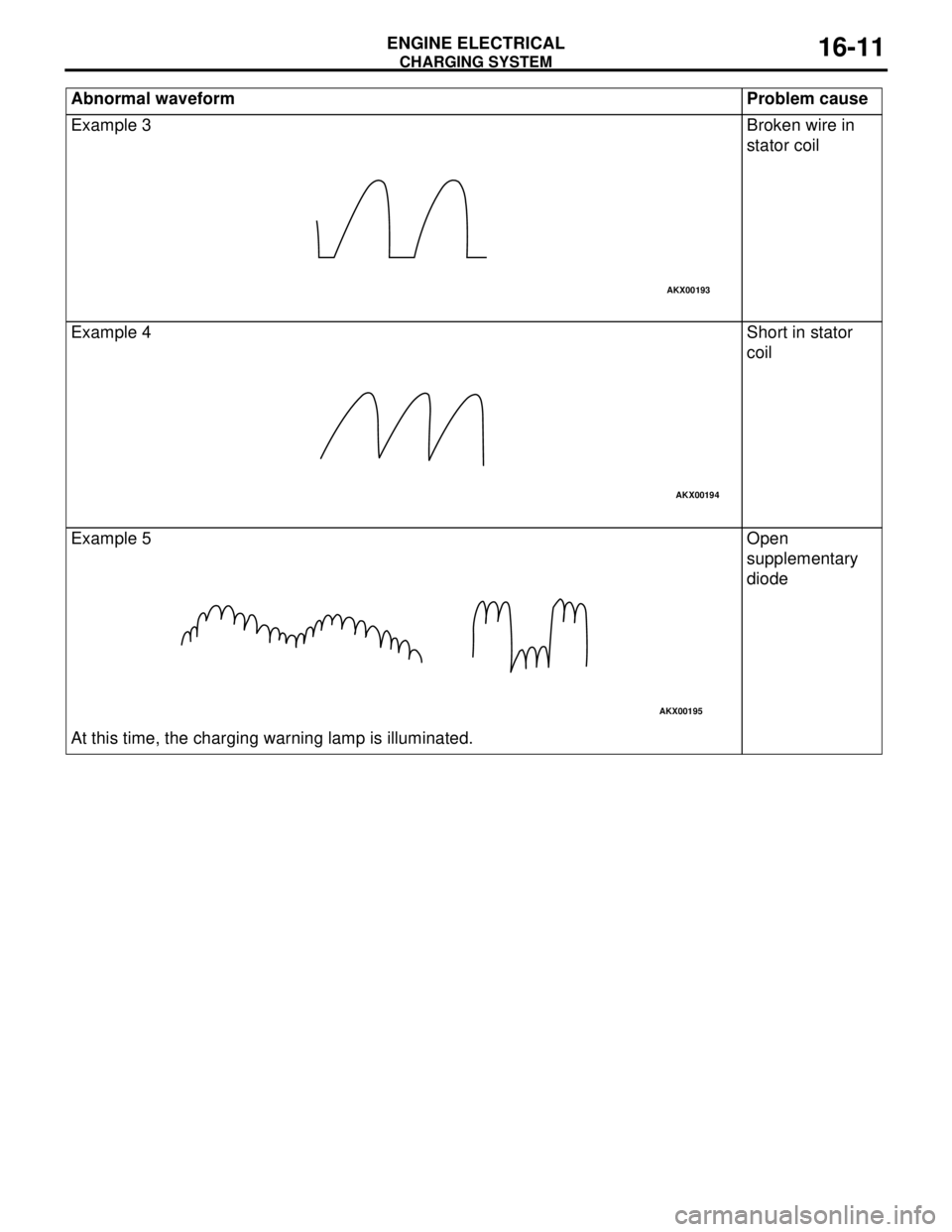
Example 3 Broken wire in
stator coil
Example 4 Short in stator
coil
Example 5
At this time, the charging warning lamp is illuminated.Open
supplementary
diode Abnormal waveform Problem cause
AKX00193
AKX00194
AKX00195
Page 78 of 788
Page 80 of 788
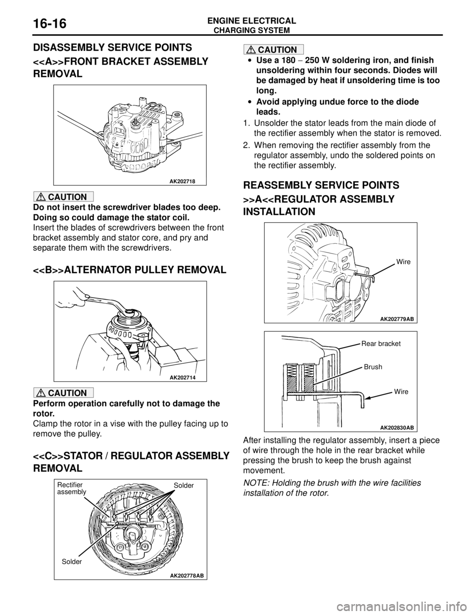
Page 81 of 788
CHARGING SYSTEM
ENGINE ELECTRICAL16-17
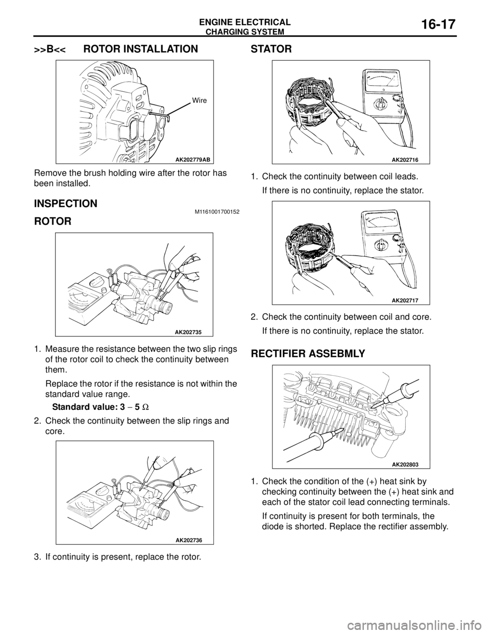
>>B<< ROTOR INSTALLATION
Remove the brush holding wire after the rotor has
been installed.
INSPECTION M1161001700152
ROTOR
1. Measure the resistance between the two slip rings
of the rotor coil to check the continuity between
them.
Replace the rotor if the resistance is not within the
standard value range.
Standard value: 3 − 5 Ω
2. Check the continuity between the slip rings and
core.
3. If continuity is present, replace the rotor.
STATOR
1. Check the continuity between coil leads.
If there is no continuity, replace the stator.
2. Check the continuity between coil and core.
If there is no continuity, replace the stator.
RECTIFIER ASSEBMLY
1. Check the condition of the (+) heat sink by
checking continuity between the (+) heat sink and
each of the stator coil lead connecting terminals.
If continuity is present for both terminals, the
diode is shorted. Replace the rectifier assembly.
AK202779
Wire
AB
AK202735
AK202736
AK202716
AK202717
AK202803