radiator MITSUBISHI LANCER 2005 User Guide
[x] Cancel search | Manufacturer: MITSUBISHI, Model Year: 2005, Model line: LANCER, Model: MITSUBISHI LANCER 2005Pages: 788, PDF Size: 45.98 MB
Page 49 of 788
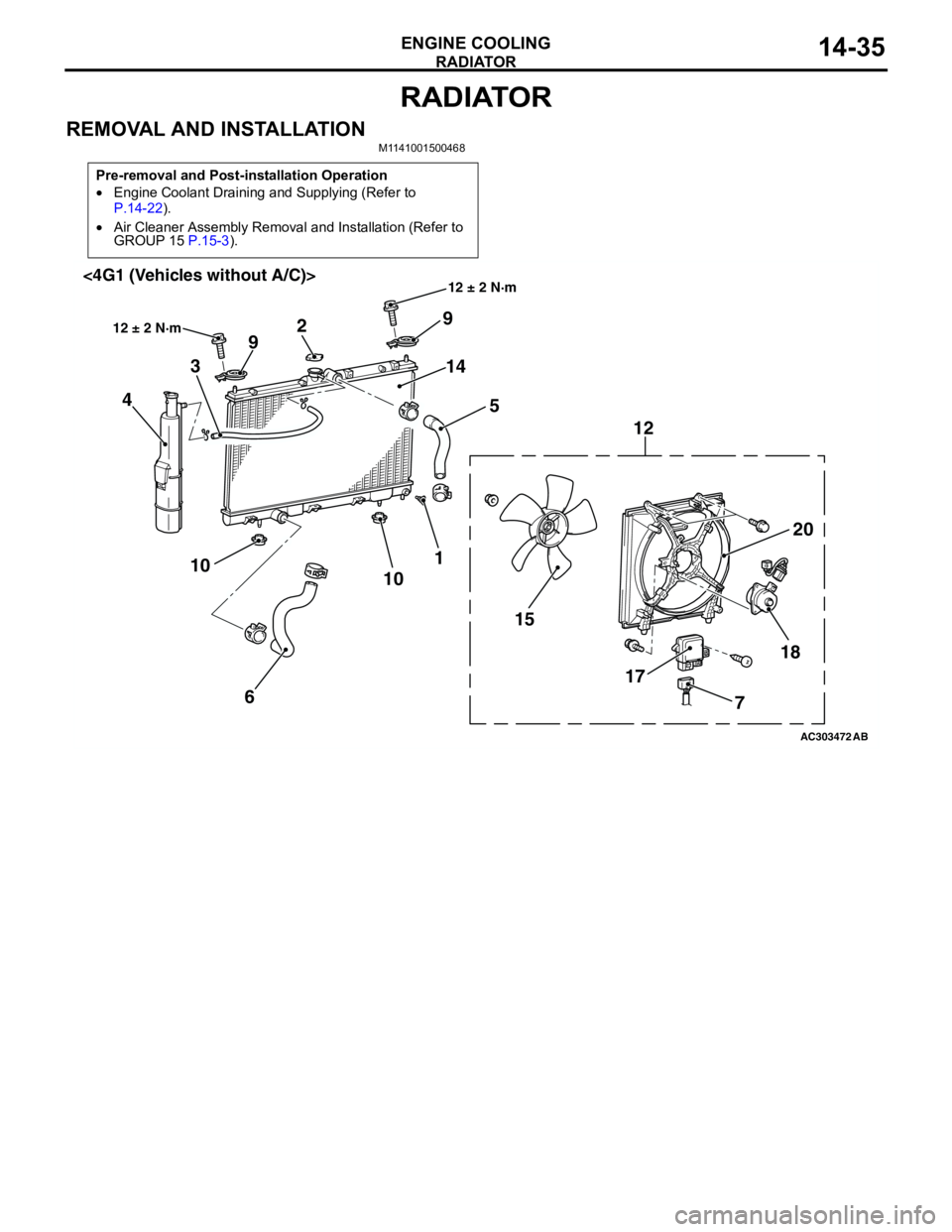
RADIATOR
ENGINE COOLING14-35
RADIATOR
REMOVAL AND INSTALLATIONM1141001500468
Pre-removal and Post-installation Operation
•Engine Coolant Draining and Supplying (Refer to
P.14-22).
•Air Cleaner Assembly Removal and Installation (Refer to
GROUP 15 P.15-3).
AC303472
18
17 1520 12 9
14
5 2
9
3
4
1
10
6 10
AB
12 ± 2 N·m
12 ± 2 N·m<4G1 (Vehicles without A/C)>
7
Page 50 of 788
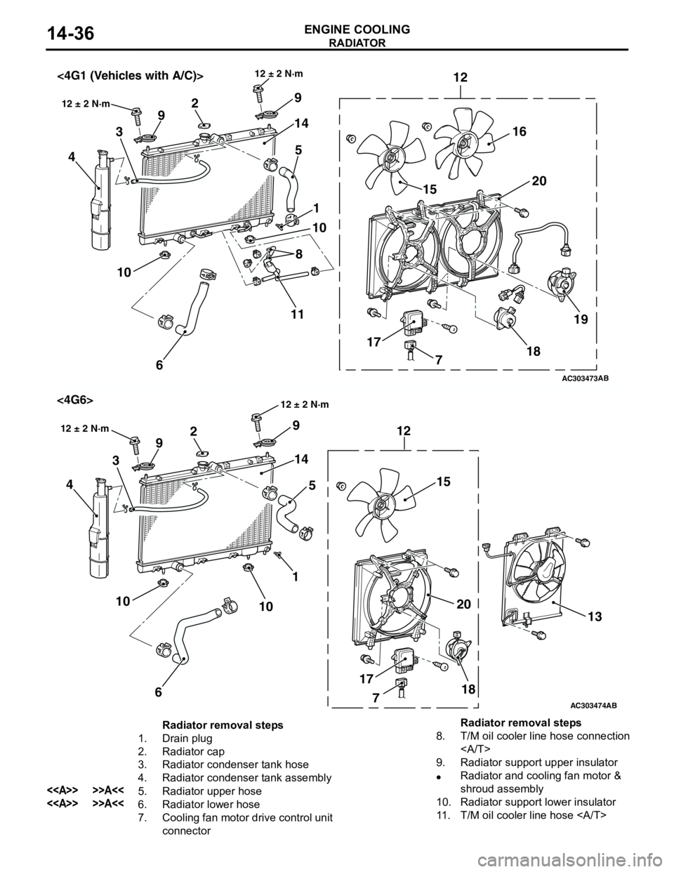
RADIATOR
ENGINE COOLING14-36
AC303473
18 171520 12
9
14
5 2
9
3
4
1
10
6 10
12 ± 2 N·m
AB
12 ± 2 N·m<4G1 (Vehicles with A/C)>
16
19
8
11
7
AC303474
18 1715
20 12 9
14
5 2
9
3
4
1
10
6 10
12 ± 2 N·m
AB
<4G6>
13
7
12 ± 2 N·m
Radiator removal steps
1. Drain plug
2. Radiator cap
3. Radiator condenser tank hose
4. Radiator condenser tank assembly
<> >>A<<5. Radiator upper hose
<> >>A<<6. Radiator lower hose
7. Cooling fan motor drive control unit
connector8. T/M oil cooler line hose connection
9. Radiator support upper insulator
•Radiator and cooling fan motor &
shroud assembly
10. Radiator support lower insulator
11. T/M oil cooler line hose Radiator removal steps
Page 51 of 788

RADIATOR
ENGINE COOLING14-37
REMOVAL SERVICE POINT
<> RADIATOR UPPER
HOSE/RADIATOR LOWER HOSE
DISCONNECTION
Make mating marks on the radiator hose and the
hose clamp. Disconnect the radiator hoses.
INSTALLATION SERVICE POINT
>>A<< RADIATOR LOWER
HOSE/RADIATOR UPPER HOSE
CONNECTION
1. Insert radiator lower hose as far as the projection
of the cooling water inlet hose fitting.
2. Insert radiator upper hose as far as the projection
of the thermostat case assembly <4G1> or the
cooling water outlet hose fitting <4G6>.
3. Align the mating marks on the radiator hose and
hose clamp, and then connect the radiator hose.
12. Cooling fan motor & shroud
assembly
13. A/C condenser fan motor & shroud
assembly <4G6>
14. Radiator assembly
Cooling fan motor removal
steps
3. Radiator condenser tank hose
<> >>A<<5. Radiator upper hose
7. Cooling fan motor drive control unit
connector Radiator removal steps
12. Cooling fan motor & shroud
assembly
15. Cooling fan (L.H.)
16. Cooling fan (R.H.) <4G1 (Vehicles
with A/C)>
17. Cooling fan motor drive control unit
18. Cooling fan motor (L.H.)
19. Cooling fan (R.H.) motor <4G1
(Vehicles with A/C)>
20. Cooling fan shroudCooling fan motor removal steps
(Continued)
AC200641AC
Mating marks
AC200642
Mating marks
Projection
Cooling water hose fitting
or thermostat case assembly
AK
Radiator hose
Page 341 of 788
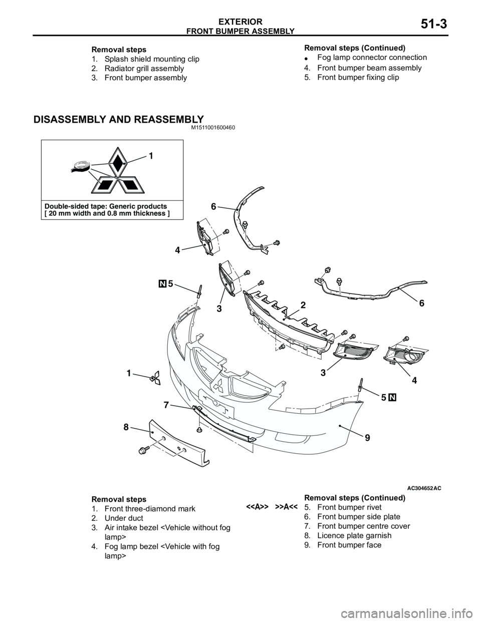
FRONT BUMPER ASSEMBLY
EXTERIOR51-3
DISASSEMBLY AND REASSEMBLYM1511001600460
Removal steps
1. Splash shield mounting clip
2. Radiator grill assembly
3. Front bumper assembly•Fog lamp connector connection
4. Front bumper beam assembly
5. Front bumper fixing clip Removal steps (Continued)
AC304652AC
Double-sided tape: Generic products
[ 20 mm width and 0.8 mm thickness ]
1
1
8
7
9
6
6
5
5
3
4
34
N
N
2
Removal steps
1. Front three-diamond mark
2. Under duct
3. Air intake bezel
4. Fog lamp bezel
6. Front bumper side plate
7. Front bumper centre cover
8. Licence plate garnish
9. Front bumper face Removal steps (Continued)
Page 457 of 788
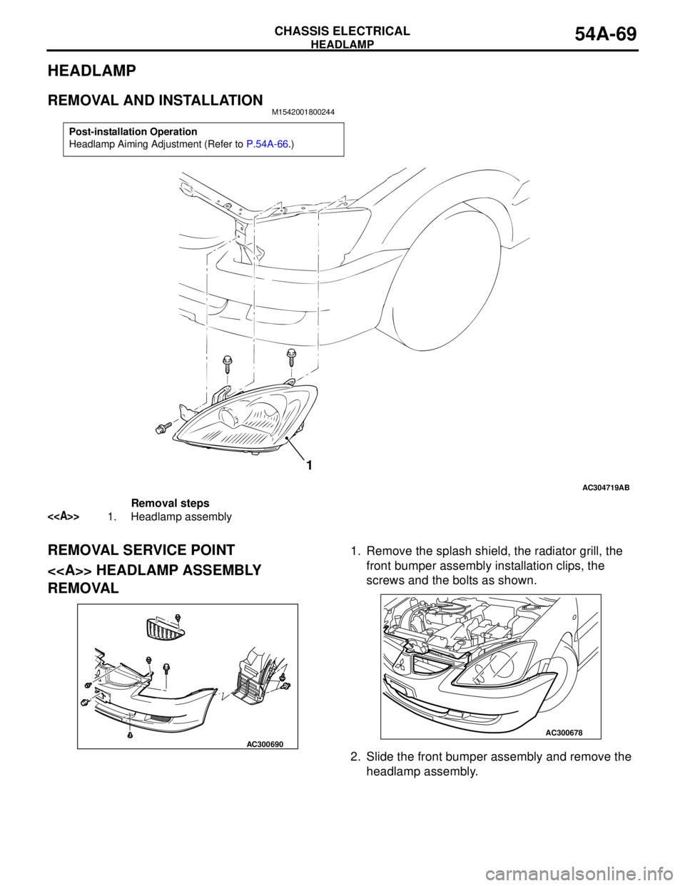
HEADLAMP
CHASSIS ELECTRICAL54A-69
HEADLAMP
REMOVAL AND INSTALLATIONM1542001800244
REMOVAL SERVICE POINT
<> HEADLAMP ASSEMBLY
REMOVAL1. Remove the splash shield, the radiator grill, the
front bumper assembly installation clips, the
screws and the bolts as shown.
2. Slide the front bumper assembly and remove the
headlamp assembly.
Post-installation Operation
Headlamp Aiming Adjustment (Refer to P.54A-66.)
AC304719
1
AB
Removal steps
<>1. Headlamp assembly
AC300690
AC300678
Page 582 of 788
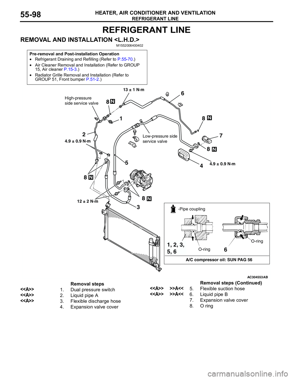
REFRIGERANT LINE
HEATER, AIR CONDITIONER AND VENTILATION55-98
REFRIGERANT LINE
REMOVAL AND INSTALLATION
Pre-removal and Post-installation Operation
•Refrigerant Draining and Refilling (Refer to P.55-70.)
•Air Cleaner Removal and Installation (Refer to GROUP
15, Air cleaner P.15-3.)
•Radiator Grille Removal and Installation (Refer to
GROUP 51, Front bumper P.51-2.)
AC304553
1
2
3
45
6
7
8N
N
N
N
N
8 8
8
8
High-pressure
side service valve
Low-pressure side
service valve
4.9 ± 0.9 N·m 13 ± 1 N·m
4.9 ± 0.9 N·m
12 ± 2 N·m
AB
6
A/C compressor oil: SUN PAG 56 -Pipe coupling
O-ringO-ring
1, 2, 3,
5, 6
Removal steps
<>1. Dual pressure switch
<>2. Liquid pipe A
<>3. Flexible discharge hose
4. Expansion valve cover
<> >>A<<5. Flexible suction hose
<> >>A<<6. Liquid pipe B
7. Expansion valve cover
8. O ringRemoval steps (Continued)
Page 583 of 788
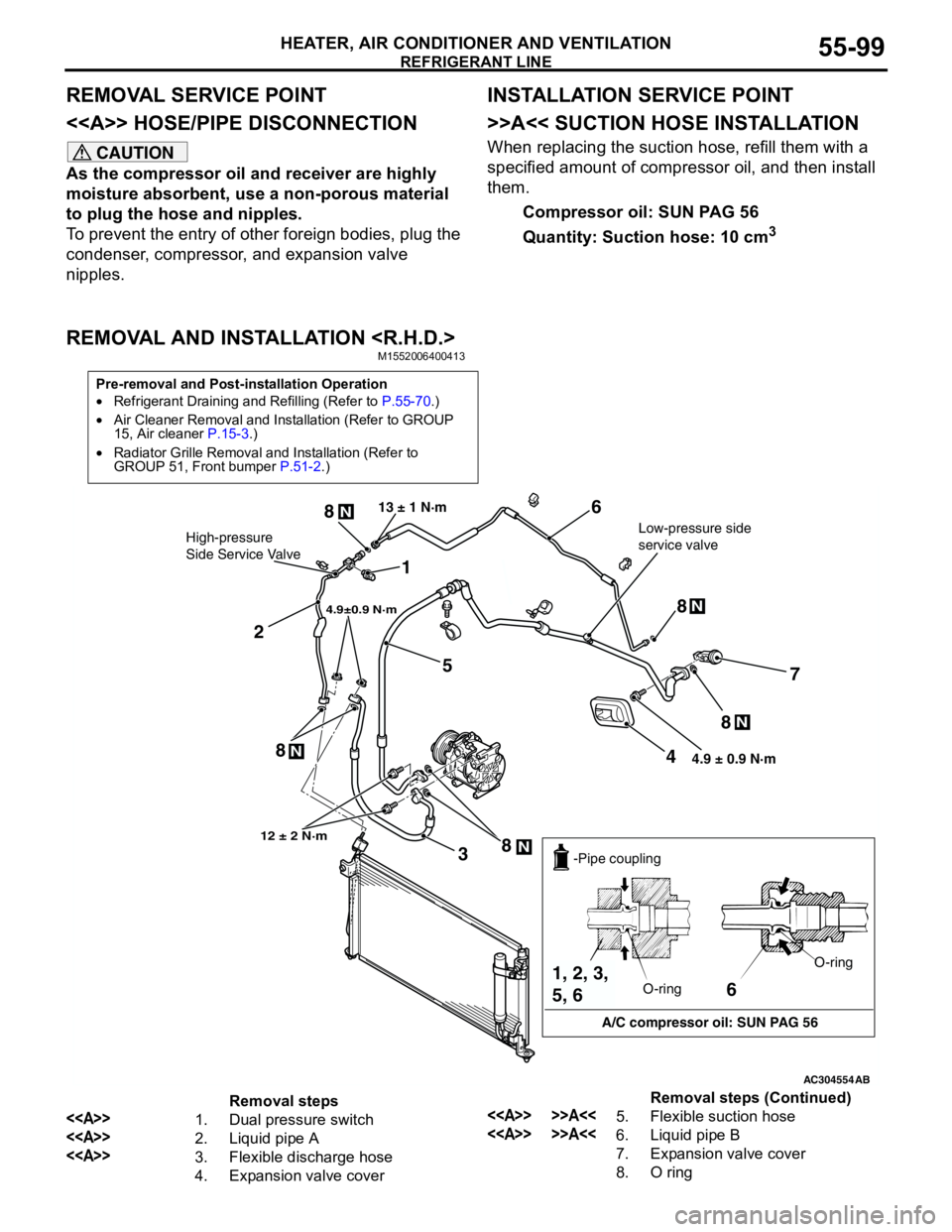
REFRIGERANT LINE
HEATER, AIR CONDITIONER AND VENTILATION55-99
REMOVAL SERVICE POINT
<> HOSE/PIPE DISCONNECTION
CAUTION
As the compressor oil and receiver are highly
moisture absorbent, use a non-porous material
to plug the hose and nipples.
To prevent the entry of other foreign bodies, plug the
condenser, compressor, and expansion valve
nipples.
INSTALLATION SERVICE POINT
>>A<< SUCTION HOSE INSTALLATION
When replacing the suction hose, refill them with a
specified amount of compressor oil, and then install
them.
Compressor oil: SUN PAG 56
Quantity: Suction hose: 10 cm
3
REMOVAL AND INSTALLATION
Pre-removal and Post-installation Operation
•Refrigerant Draining and Refilling (Refer to P.55-70.)
•Air Cleaner Removal and Installation (Refer to GROUP
15, Air cleaner P.15-3.)
•Radiator Grille Removal and Installation (Refer to
GROUP 51, Front bumper P.51-2.)
AC304554
1
2
3
4
5
6
7
8N
8N
8N
N8 8
N
4.9±0.9 N·m
Low-pressure side
service valve 13 ± 1 N·mHigh-pressure
Side Service Valve
12 ± 2 N·m
4.9 ± 0.9 N·m
AB
6
A/C compressor oil: SUN PAG 56 -Pipe coupling
O-ringO-ring
1, 2, 3,
5, 6
Removal steps
<>1. Dual pressure switch
<>2. Liquid pipe A
<>3. Flexible discharge hose
4. Expansion valve cover
<> >>A<<5. Flexible suction hose
<> >>A<<6. Liquid pipe B
7. Expansion valve cover
8. O ringRemoval steps (Continued)
Page 589 of 788
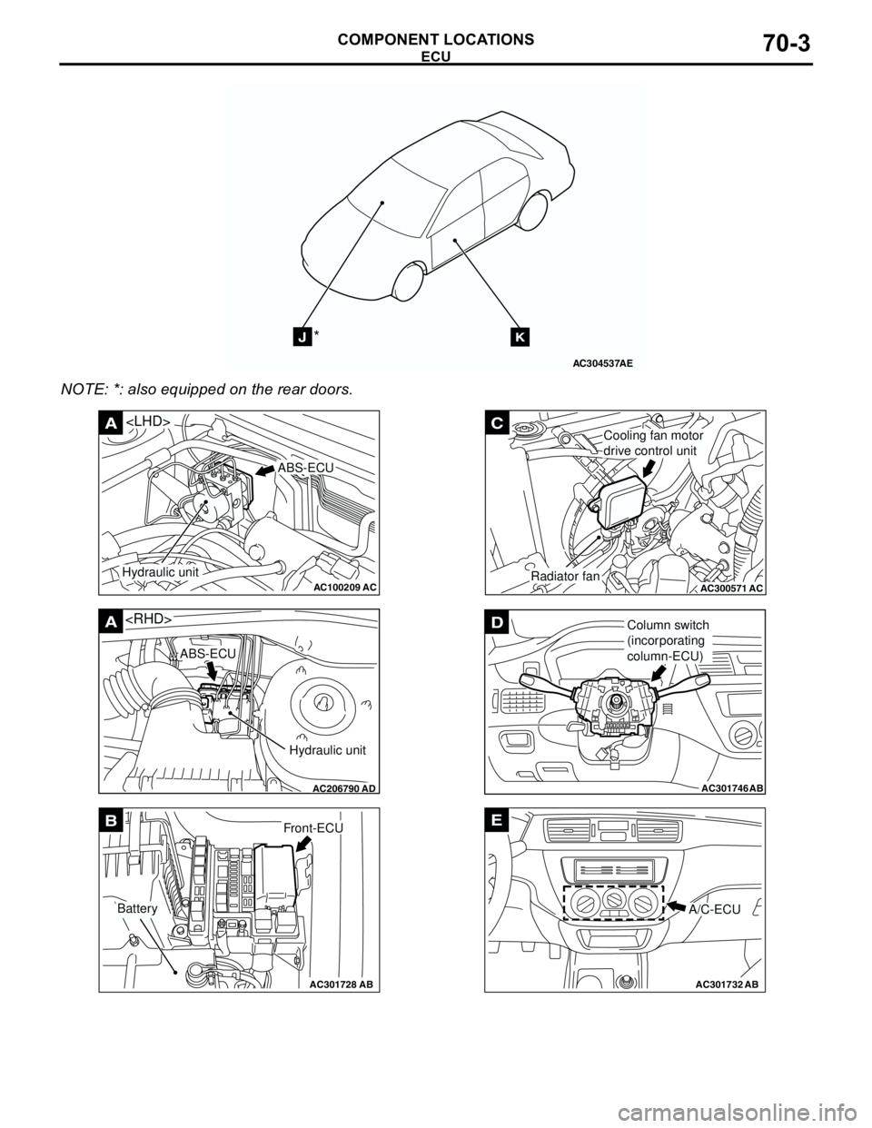
ECU
COMPONENT LOCATIONS70-3
NOTE: *: also equipped on the rear doors.
AC304537
JK*
AE
AC100209AC
A
ABS-ECU
Hydraulic unit
AC206790
A
AD
ABS-ECU
Hydraulic unit
AC301728AB
BFront-ECU
Battery
AC300571
C
ACRadiator fan
Cooling fan motor
drive control unit
AC301746
DColumn switch
(incorporating
column-ECU)
AB
AC301732AB
E
A/C-ECU
Page 591 of 788
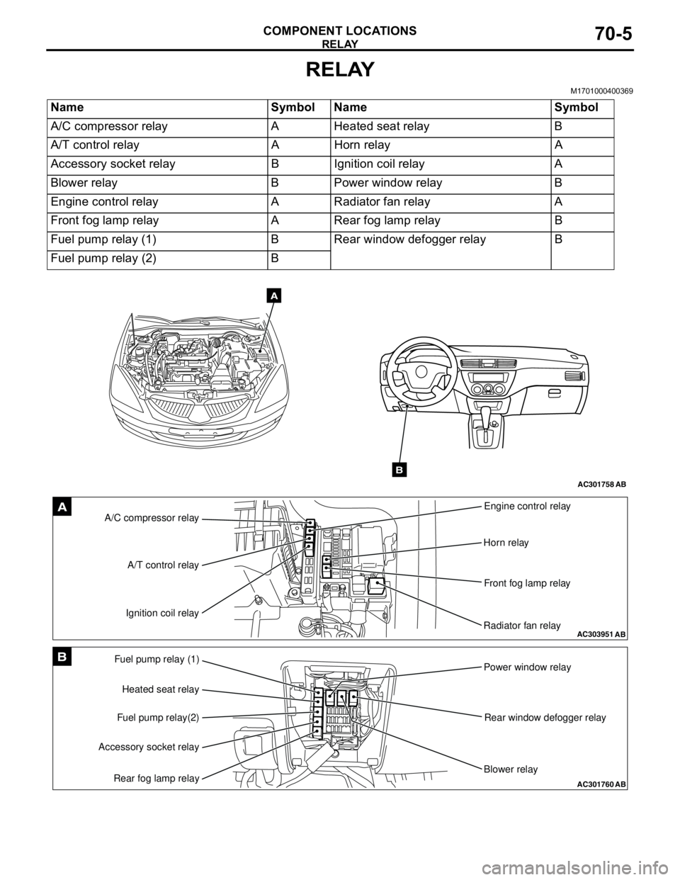
RELAY
COMPONENT LOCATIONS70-5
RELAY
M1701000400369
Name Symbol Name Symbol
A/C compressor relay A Heated seat relay B
A/T control relay A Horn relay A
Accessory socket relay B Ignition coil relay A
Blower relay B Power window relay B
Engine control relay A Radiator fan relay A
Front fog lamp relay A Rear fog lamp relay B
Fuel pump relay (1) B Rear window defogger relay B
Fuel pump relay (2) B
AC301758AB
A
B
AC303951AB
A/C compressor relayEngine control relay
Horn relay
Front fog lamp relay
Radiator fan relay A/T control relay
Ignition coil relayA
AC301760
Fuel pump relay (1)
Power window relay
Rear window defogger relay
Blower relay Heated seat relay
Fuel pump relay(2)
Accessory socket relay
Rear fog lamp relayAB
B
Page 679 of 788
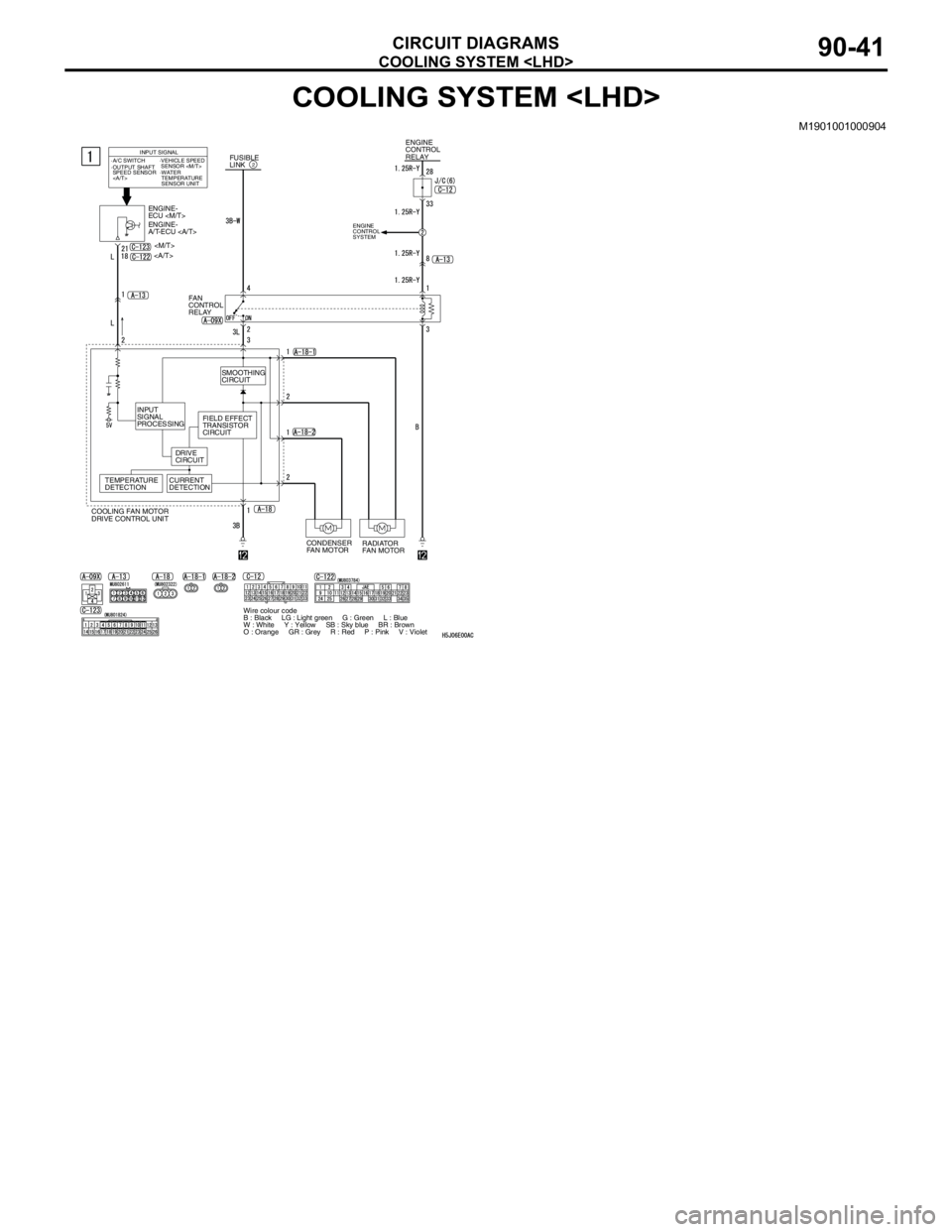
COOLING SYSTEM
CIRCUIT DIAGRAMS90-41
COOLING SYSTEM
M1901001000904
FUSIBLE
LINK2
ENGINE
CONTROL
RELAY
ENGINE-
ECU
ENGINE-
A/T-ECU
FAN
CONTROL
RELAY
RADIATOR
FAN MOTOR CONDENSER
FAN MOTOR COOLING FAN MOTOR
DRIVE CONTROL UNITINPUT SIGNAL
·A/C SWITCH
·WATER
TEMPERATURE
SENSOR UNIT ·OUTPUT SHAFT
SPEED SENSOR
·VEHICLE SPEED
SENSOR
SMOOTHING
CIRCUIT
INPUT
SIGNAL
PROCESSING
DRIVE
CIRCUITFIELD EFFECT
TRANSISTOR
CIRCUIT
TEMPERATURE
DETECTIONCURRENT
DETECTION
Wire colour code
B : Black LG : Light green G : Green L : Blue
W : White Y : Yellow SB : Sky blue BR : Brown
O : Orange GR : Grey R : Red P : Pink V : Violet
ENGINE
CONTROL
SYSTEM