MITSUBISHI LANCER EVOLUTION 2007 Service Repair Manual
Manufacturer: MITSUBISHI, Model Year: 2007, Model line: LANCER EVOLUTION, Model: MITSUBISHI LANCER EVOLUTION 2007Pages: 1449, PDF Size: 56.82 MB
Page 1131 of 1449

STEERING - Power Steering Gear Box and Linkage37A-17
17 6 2
3 4
15±3 N·m
57±7 N·m
5
70±10 N·m
Removal steps
1. Crossmember
(Refer to GROUP 32.)
2. Joint cover grommet
3. Return hose connection4. Return tube
5. Pressure hose connection
6. Clamp
7. Steering gear and linkage
INSPECTION
GEAR BOX PINION TOTAL ROTATION TORQUE CHECK
Caution
Secure the steering gear box and linkage in their mounting
positions only. Otherwise, deformation or damage could
result.
1. Using the special tool, turn the pinion gear at a speed
of one rotation per 4 to 6 seconds to measure total rotation
torque.
Standard values:
Total rotation torque: 0.8 – 1.8 N·m
Torque fluctuation: 0.49 N·m or less
NOTE
(1) Remove the bellows from the rack housing before
measuring.
(2) Measure the total rotation torque by turning the special
tool left and right 180_from the neutral position.
2. If the standard values are not met, adjust the pinion total
rotation torque. (Refer to P.37A-26.)
3. In case the adjustment is impossible, disassemble and
check the components, and repair if necessary.
MB991006
Page 1132 of 1449

STEERING - Power Steering Gear Box and Linkage37A-18
TIE ROD SWING RESISTANCE CHECK
1. Swing the tie rod 10 times hardly.
2. With the tie rod end downwards as shown, use a spring
scale to measure swing resistance (swing torque).
Standard value: 8 - 27 N (1.5 - 4.9 N·m)
3. If the measured value is above the standard value, replace
the tie rod.
4. If below, check the ball joint for looseness or ratcheting.
The tie rod is still serviceable when the ball joint swings
smoothly.
TIE ROD END BALL JOINT DUST COVER CHECK
1. Check the dust cover for cracks or damage by pushing
it with finger.
2. If the dust cover is cracked or damaged, replace the
tie rod end. (Refer to P.37A-19, 20.)
NOTE
A cracked or damaged dust cover may damage the ball
joint. Replace the dust cover when it is damaged during
service work.
Page 1133 of 1449

STEERING - Power Steering Gear Box and Linkage37A-19
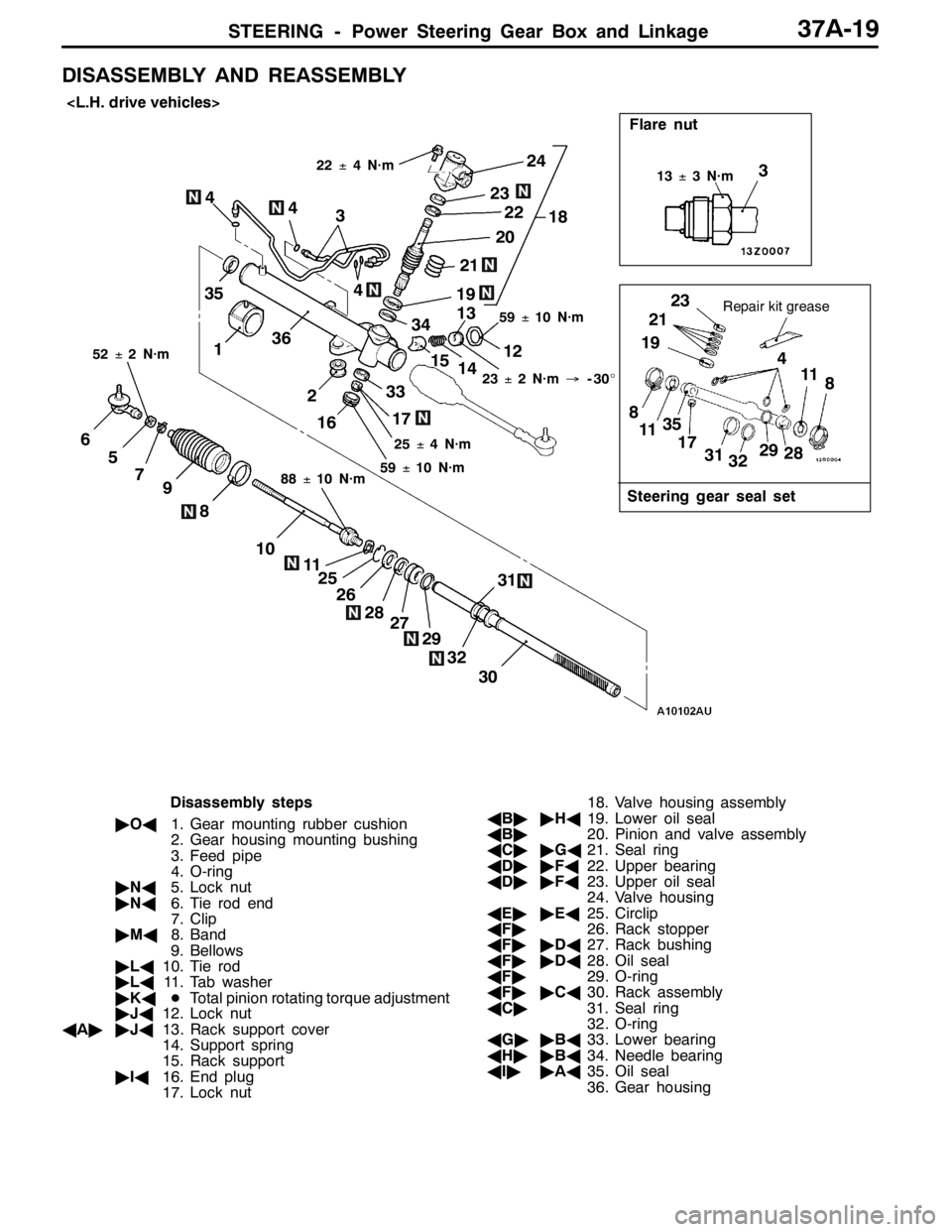
DISASSEMBLY AND REASSEMBLY
31
30
28
11
10
8
97
5
6
29
2618
33
22
20
Flare nut
21
23
36
32 17
1615
14 13
12 3
19
Steering gear seal set
Repair kit grease35
23
21
19
8
1135
17
32 3129
2811
8 3
4 4
27 25
22±4 N·m
25±4 N·m59±10 N·m
88±10 N·m 52±2 N·m
13±3 N·m
1
2 4
23±2 N·m→-30_
59±10 N·m
34
24
4
Disassembly steps
"OA1. Gear mounting rubber cushion
2. Gear housing mounting bushing
3. Feed pipe
4. O-ring
"NA5. Lock nut
"NA6. Tie rod end
7. Clip
"MA8. Band
9. Bellows
"LA10. Tie rod
"LA11. Tab washer
"KADTotal pinion rotating torque adjustment
"JA12. Lock nut
AA""JA13. Rack support cover
14. Support spring
15. Rack support
"IA16. End plug
17. Lock nut18. Valve housing assembly
AB""HA19. Lower oil seal
AB"20. Pinion and valve assembly
AC""GA21. Seal ring
AD""FA22. Upper bearing
AD""FA23. Upper oil seal
24. Valve housing
AE""EA25. Circlip
AF"26. Rack stopper
AF""DA27. Rack bushing
AF""DA28. Oil seal
AF"29. O-ring
AF""CA30. Rack assembly
AC"31. Seal ring
32. O-ring
AG""BA33. Lower bearing
AH""BA34. Needle bearing
AI""AA35. Oil seal
36. Gear housing
Page 1134 of 1449

STEERING - Power Steering Gear Box and Linkage37A-20
18
24
23
22
21
20
34
36
33
17
1615
14
13
123
19
3523
21
19
8
1135
17
31
3229
2811
8
3
4 4
31
32
27
29
28
26
25
1110
8
9
756
304
22±4 N·m
25±4 N·m
59±10 N·m
59±10 N·m
88±10 N·m
52±2 N·m
23±2 N·m→–30_
13±3 N·m
1 2
4
Flare nut
Steering gear seal set
Repair kit grease3
4
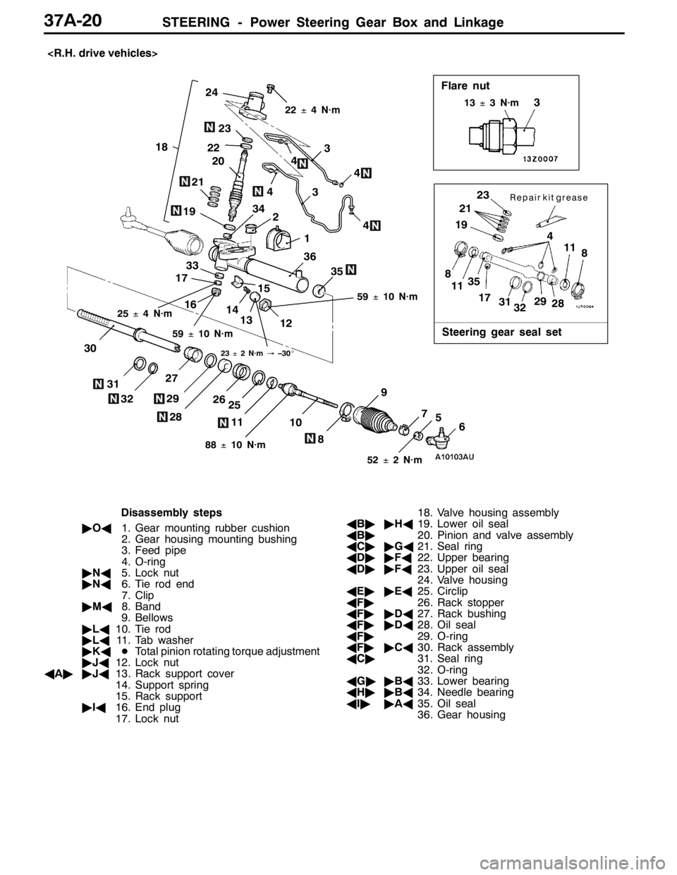
Disassembly steps
"OA1. Gear mounting rubber cushion
2. Gear housing mounting bushing
3. Feed pipe
4. O-ring
"NA5. Lock nut
"NA6. Tie rod end
7. Clip
"MA8. Band
9. Bellows
"LA10. Tie rod
"LA11. Tab washer
"KADTotal pinion rotating torque adjustment
"JA12. Lock nut
AA""JA13. Rack support cover
14. Support spring
15. Rack support
"IA16. End plug
17. Lock nut18. Valve housing assembly
AB""HA19. Lower oil seal
AB"20. Pinion and valve assembly
AC""GA21. Seal ring
AD""FA22. Upper bearing
AD""FA23. Upper oil seal
24. Valve housing
AE""EA25. Circlip
AF"26. Rack stopper
AF""DA27. Rack bushing
AF""DA28. Oil seal
AF"29. O-ring
AF""CA30. Rack assembly
AC"31. Seal ring
32. O-ring
AG""BA33. Lower bearing
AH""BA34. Needle bearing
AI""AA35. Oil seal
36. Gear housing
Page 1135 of 1449

STEERING - Power Steering Gear Box and Linkage37A-21
Lubrication and Sealing Points
Fluid:
Automatic transmission
fluid DEXRON II
Fluid:
Automatic transmission
fluid DEXRON II
Fluid:
Automatic transmission
fluid DEXRON II
Fluid:
Automatic transmission
fluid DEXRON II
Grease: Repair kit grease
Sealant: 3M ATD part No. 8661,
8663 or equivalent
Fluid:
Automatic transmission
fluid DEXRON II
Grease: Repair kit grease
Fluid:
Automatic transmission
fluid DEXRON II
Grease: Silicone grease
Page 1136 of 1449

STEERING - Power Steering Gear Box and Linkage37A-22
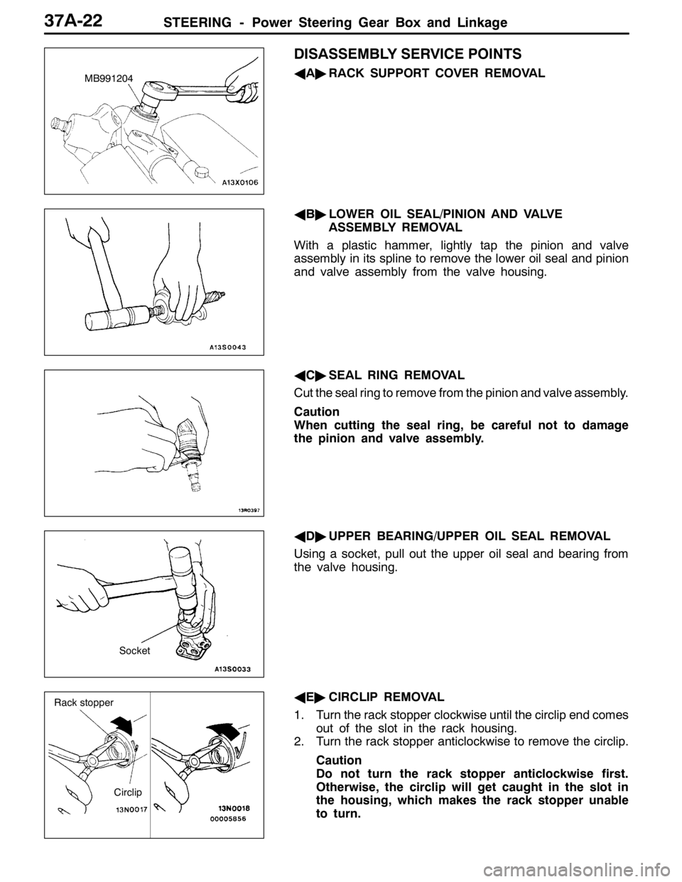
DISASSEMBLY SERVICE POINTS
AA"RACK SUPPORT COVER REMOVAL
AB"LOWER OIL SEAL/PINION AND VALVE
ASSEMBLY REMOVAL
With a plastic hammer, lightly tap the pinion and valve
assembly in its spline to remove the lower oil seal and pinion
and valve assembly from the valve housing.
AC"SEAL RING REMOVAL
Cut the seal ring to remove from the pinion and valve assembly.
Caution
When cutting the seal ring, be careful not to damage
the pinion and valve assembly.
AD"UPPER BEARING/UPPER OIL SEAL REMOVAL
Using a socket, pull out the upper oil seal and bearing from
the valve housing.
AE"CIRCLIP REMOVAL
1. Turn the rack stopper clockwise until the circlip end comes
out of the slot in the rack housing.
2. Turn the rack stopper anticlockwise to remove the circlip.
Caution
Do not turn the rack stopper anticlockwise first.
Otherwise, the circlip will get caught in the slot in
the housing, which makes the rack stopper unable
to turn.MB991204
Socket
Circlip
Rack stopper
Page 1137 of 1449

STEERING - Power Steering Gear Box and Linkage37A-23
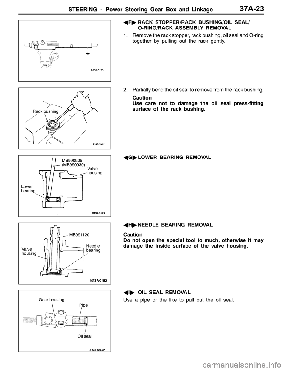
AF"RACK STOPPER/RACK BUSHING/OIL SEAL/
O-RING/RACK ASSEMBLY REMOVAL
1. Remove the rack stopper, rack bushing, oil seal and O-ring
together by pulling out the rack gently.
2. Partially bend the oil seal to remove from the rack bushing.
Caution
Use care not to damage the oil seal press-fitting
surface of the rack bushing.
AG"LOWER BEARING REMOVAL
AH"NEEDLE BEARING REMOVAL
Caution
Do not open the special tool to much, otherwise it may
damage the inside surface of the valve housing.
AI"OIL SEAL REMOVAL
Use a pipe or the like to pull out the oil seal.
Rack bushing
Valve
housing
MB990925
(MB990939)
Lower
bearing
MB991120
Needle
bearing Valve
housing
Oil seal
Gear housing
Pipe
Page 1138 of 1449

STEERING - Power Steering Gear Box and Linkage37A-24
REASSEMBLY SERVICE POINTS
"AAOIL SEAL INSTALLATION
"BANEEDLE BEARING/LOWER BEARING
INSTALLATION
"CARACK ASSEMBLY INSTALLATION
1. Apply repair kit grease to the teeth of the rack assembly.
Caution
Use care not to close the vent hole in the rack with
grease.
2. Cover the serrations of the rack assembly with the special
tool.
3. Apply specified fluid to the outer surfaces of the special
tool, seal ring and O-ring.
Specified fluid:
Automatic transmission fluid DEXRONII
Caution
Do not use ATF-SPIIM and ATF-SPIII.
4. Slowly insert the rack covered with the special tool from
the power cylinder side of the gear housing.
Caution
Carefully push in the rack with the oil seal centre
and the special tool end matched. This is to avoid
the retainer spring coming off.MB991197
Gear housing
Oil seal MB991199
Needle
bearingMB990925
(MB990938)
MB991202
Lower
bearing MB990925
(MB990938)
MB991202
Vent hole
Seal ring, O-ring
MB991214 Oil seal
Page 1139 of 1449

STEERING - Power Steering Gear Box and Linkage37A-25
"DAOIL SEAL/RACK BUSHING INSTALLATION
1. Apply specified fluid to the outer surface of the oil seal.
Using the special tool, press in the oil seal until it is flush
with the bushing end face.
Specified fluid:
Automatic transmission fluid DEXRONII
Caution
Do not use ATF-SPIIM and ATF-SPIII.
2. Apply the specified fluid to the oil seal inner surface and
the O-ring.
Specified fluid:
Automatic transmission fluid DEXRONII
Caution
Do not use ATF-SPIIM and ATF-SPIII.
3. Wrap the rack end with plastic tape, and push the rack
bushing onto the rack.
"EACIRCLIP INSTALLATION
Align the mark on the rack stopper and the slot in the cylinder.
Then, insert the circlip into the rack stopper hole through
the cylinder hole. Turn the rack stopper clockwise and insert
the circlip firmly.
"FAUPPER OIL SEAL/UPPER BEARING
INSTALLATION
"GASEAL RING INSTALLATION
After installation, using the special tool or by hand, compress
seal rings that expand during installation.
MB990925
(MB990927)
Oil seal
O-ring
Rack
bushing
Rack bushingPlastic tape Rack
Slot
Circlip
SlotCirclip
MB991203MB991203 MB990925
(MB990938)
Upper oil
seal
MB990925
(MB990938)
Bearing
MB991317
Page 1140 of 1449

STEERING - Power Steering Gear Box and Linkage37A-26
"HALOWER OIL SEAL INSTALLATION
Using the special tool, press the oil seal into the valve housing.
The upper surface of the oil seal must project outwards about
1 mm from the housing end surface.
Caution
When the oil seal is flush with or lower than the housing
edge, reassemble the components. Otherwise, oil leaks
will result.
"IAEND PLUG INSTALLATION
1. Apply specified sealant to the threaded section of the
end plug, and then install the end plug to the gear housing.
Specified fluid:
3M ATD Part No.8661, 8663 or equivalent
2. Use a punch to bend over the two tabs on the sides
of the end plug to stop the end plug from turning.
"JARACK SUPPORT COVER/LOCKING NUT
INSTALLATION
1. Apply specified sealant to the rack support cover thread.
Specified fluid:
3M ATD Part No.8661, 8663 or equivalent
2. Using the special tool, tighten the rack support cover
to 23±2 N·m.
3. Return the rack support cover by about 30_.
4. Tighten the locking nut to the specified torque, using
the special tool to prevent the rack support cover from
spinning.
"KAPINION TOTAL ROTATION TORQUE ADJUSTMENT
1. Using the special tool, measure total rotation torque by
turning the pinion gear at a speed of one rotation per
4 to 6 seconds.
Standard value:
Total rotation torque: 0.8-1.8 Nm
Torque fluctuation: 0.49 Nm or lessMB990941 Approx. 1 mmOil
seal
Housing
End plugEnd plug
MB991204
MB991006