MITSUBISHI LANCER EVOLUTION 2007 Service Repair Manual
Manufacturer: MITSUBISHI, Model Year: 2007, Model line: LANCER EVOLUTION, Model: MITSUBISHI LANCER EVOLUTION 2007Pages: 1449, PDF Size: 56.82 MB
Page 1141 of 1449

STEERING - Power Steering Gear Box and Linkage37A-27
2. If the total rotation torque or torque fluctuation does not
meet the standard values, adjust by returning the rack
support cover within a range of 0 to 30_.
Caution
(1) Adjust around the maximum limit of the standard
values.
(2) See that no ratcheting or catching are present
when operating the rack towards the shaft
direction.
(3) Measure the total pinion torque through the whole
stroke of the rack.
3. If the adjustment is impossible in the given range, check
the components of the rack support cover, and replace
if necessary.
"LATAB WASHER/TIE ROD INSTALLATION
After installing the tie rod to the rack, fold the tab washer
end (2 locations) to the tie rod notch.
"MABELLOWS BAND INSTALLATION
1. Turn the adjusting bolt of the special tool to adjust the
opening dimension (W) to the standard value.
Standard value (W): 2.9 mm
Screw in the adjusting bolt.
Loosen the adjusting bolt.
NOTE
(1) The dimension (W) is adjusted by about 0.7 mm per
one turn.
(2) Do not turn the adjusting bolt more than one turn.
2. Use the special tool to crimp the bellows band.
Caution
(1) Hold the rack housing, and use the special tool
to crimp the bellows band securely.
(2) Crimp the bellows band until the special tool
touches the stopper.
MB991561
Stopper
Adjusting bolt W
MB991561
Page 1142 of 1449

STEERING - Power Steering Gear Box and Linkage37A-28
3. See that the crimped width (A) meets the standard value.
Standard value (A): 2.4-2.8 mm
Readjust the dimension (W) of step (1) to the value
calculated by the following equation, and repeat step
(2).
W = 5.5 mm-A [Example: If (A) is 2.9 mm, (W)
is 2.6 mm.]
Remove the bellows band, readjust the dimension
(W) of step (1) to the value calculated by the following
equation, and use a new bellows band to repeat steps
(2) to (3).
W = 5.5 mm-A [Example: If (A) is 2.3 mm, (W)
is 3.2 mm.]
"NATIE ROD END/LOCKING NUT INSTALLATION
Screw in the tie rod end until the dimension shown is achieved.
Then, temporarily tighten with the locking nut.
NOTE
The locking nut must be tightened securely only after the
power steering gear box and linkage are installed to the vehicle
and toe-in is adjusted.
"OAGEAR MOUNTING RUBBER INSTALLATION
Install the gear mounting rubber to the rack housing so that
the distance is as shown in the illustration.
TIE ROD END BALL JOINT DUST COVER
REPLACEMENT
Only when the dust cover is damaged accidentally during
service work, replace the dust cover as follows:
1. Apply grease to the inside of the dust cover.
2. Drive in the dust cover with special tool until it is fully
seated.
3. Check the dust cover for cracks or damage by pushing
it with finger.
A
Edge of bellows
assembly grooveLocking nut
184 mm
220 mm
MB990776
Page 1143 of 1449
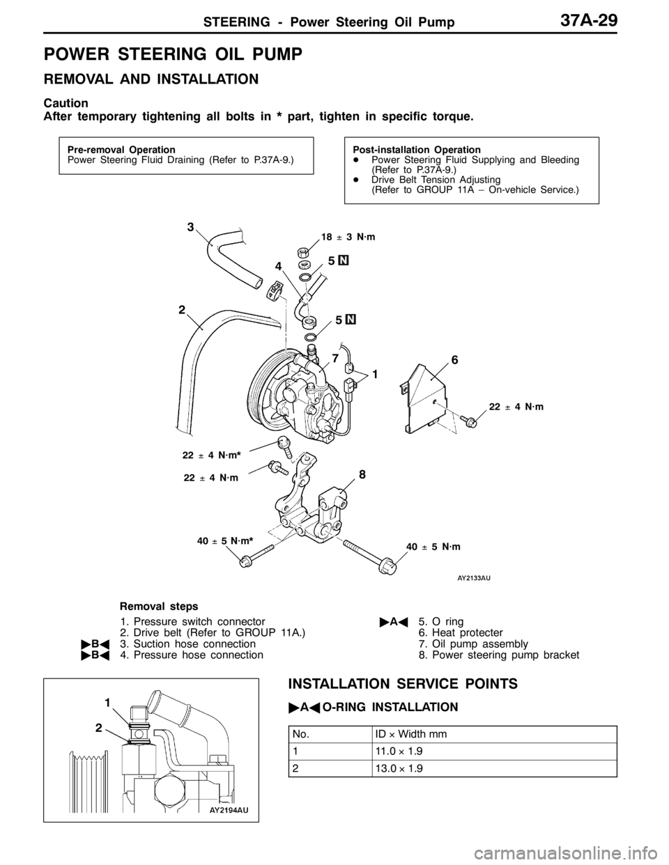
STEERING - Power Steering Oil Pump37A-29
POWER STEERING OIL PUMP
REMOVAL AND INSTALLATION
Caution
After temporary tightening all bolts in * part, tighten in specific torque.
Pre-removal Operation
Power Steering Fluid Draining (Refer to P.37A-9.)Post-installation Operation
DPower Steering Fluid Supplying and Bleeding
(Refer to P.37A-9.)
DDrive Belt Tension Adjusting
(Refer to GROUP 11A – On-vehicle Service.)
22±4 N·m
8
40±5 N·m 18±3 N·m
3
45
2
5
22±4 N·m*
1 7
6
40±5 N·m* 22±4 N·m
Removal steps
1. Pressure switch connector
2. Drive belt (Refer to GROUP 11A.)
"BA3. Suction hose connection
"BA4. Pressure hose connection"AA5. O ring
6. Heat protecter
7. Oil pump assembly
8. Power steering pump bracket
INSTALLATION SERVICE POINTS
"AAO-RING INSTALLATION
No.ID×Width mm
111.0×1.9
213.0×1.9
21
Page 1144 of 1449
STEERING - Power Steering Oil Pump/Power Steering Oil Hoses37A-30
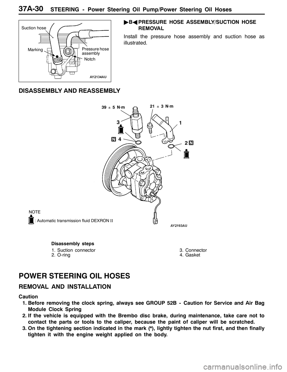
"BAPRESSURE HOSE ASSEMBLY/SUCTION HOSE
REMOVAL
Install the pressure hose assembly and suction hose as
illustrated.
DISASSEMBLY AND REASSEMBLY
21±3 N·m
3
4
2 1
39±5 N·m
: Automatic transmission fluid DEXRONII
NOTE
Disassembly steps
1. Suction connector
2. O-ring3. Connector
4. Gasket
POWER STEERING OIL HOSES
REMOVAL AND INSTALLATION
Caution
1. Before removing the clock spring, always see GROUP 52B - Caution for Service and Air Bag
Module Clock Spring
2. If the vehicle is equipped with the Brembo disc brake, during maintenance, take care not to
contact the parts or tools to the caliper, because the paint of caliper will be scratched.
3. On the tightening section indicated in the mark (*), lightly tighten the nut first, and then finally
tighten it with the engine weight applied on the body.
Suction hose
Pressure hose
assembly
Marking
Notch
Page 1145 of 1449
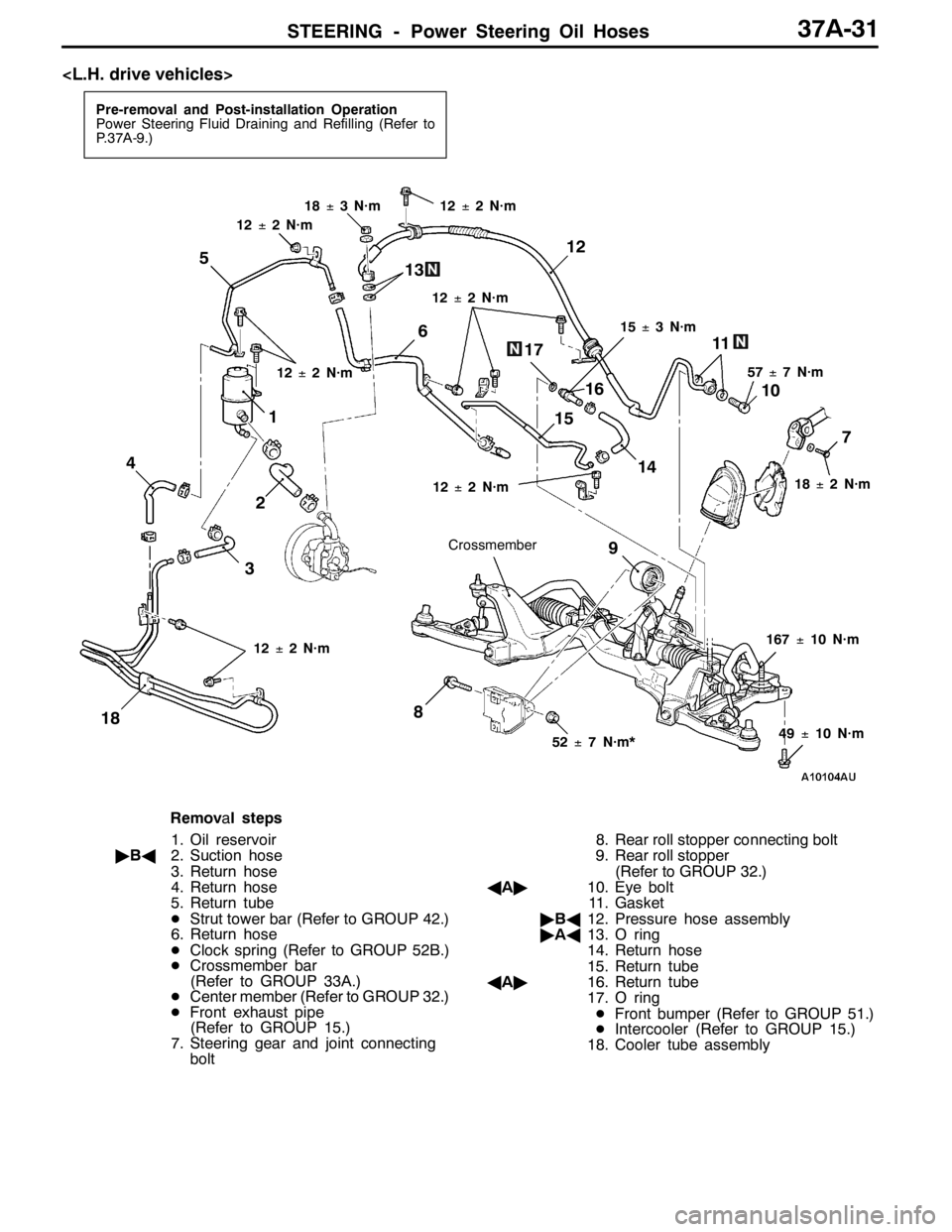
STEERING - Power Steering Oil Hoses37A-31
Pre-removal and Post-installation Operation
Power Steering Fluid Draining and Refilling (Refer to
P.37A-9.)
12±2 N·m
17
16
15
12
18±3 N·m
Crossmember
1
57±7 N·m
9
8 47
32 5
12±2 N·m15±3 N·m
18±2 N·m 12±2 N·m
49±10 N·m
52±7 N·m*
12±2 N·m
6
10
11
167±10 N·m
14 13
18
12±2 N·m
12±2 N·m
Removal steps
1. Oil reservoir
"BA2. Suction hose
3. Return hose
4. Return hose
5. Return tube
DStrut tower bar (Refer to GROUP 42.)
6. Return hose
DClock spring (Refer to GROUP 52B.)
DCrossmember bar
(Refer to GROUP 33A.)
DCenter member (Refer to GROUP 32.)
DFront exhaust pipe
(Refer to GROUP 15.)
7. Steering gear and joint connecting
bolt8. Rear roll stopper connecting bolt
9. Rear roll stopper
(Refer to GROUP 32.)
AA"10. Eye bolt
11. Gasket
"BA12. Pressure hose assembly
"AA13. O ring
14. Return hose
15. Return tube
AA"16. Return tube
17. O ring
DFront bumper (Refer to GROUP 51.)
DIntercooler (Refer to GROUP 15.)
18. Cooler tube assembly
Page 1146 of 1449
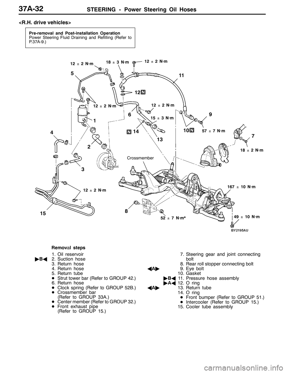
STEERING - Power Steering Oil Hoses37A-32
Pre-removal and Post-installation Operation
Power Steering Fluid Draining and Refilling (Refer to
P.37A-9.)
12±2 N·m
15
12
18±3 N·m
Crossmember
1
57±7 N·m
9
8 4
7
32 5
12±2 N·m
15±3 N·m
18±2 N·m 12±2 N·m
49±10 N·m
52±7 N·m*
12±2 N·m
6
10
11
167±10 N·m
14
13
12±2 N·m
Removal steps
1. Oil reservoir
"BA2. Suction hose
3. Return hose
4. Return hose
5. Return tube
DStrut tower bar (Refer to GROUP 42.)
6. Return hose
DClock spring (Refer to GROUP 52B.)
DCrossmember bar
(Refer to GROUP 33A.)
DCenter member (Refer to GROUP 32.)
DFront exhaust pipe
(Refer to GROUP 15.)7. Steering gear and joint connecting
bolt
8. Rear roll stopper connecting bolt
AA"9. Eye bolt
10. Gasket
"BA11. Pressure hose assembly
"AA12. O ring
AA"13. Return tube
14. O ring
DFront bumper (Refer to GROUP 51.)
DIntercooler (Refer to GROUP 15.)
15. Cooler tube assembly
Page 1147 of 1449
STEERING - Power Steering Oil Hoses37A-33
REMOVAL SERVICE POINT
AA"EYE BOLT/RETURN TUBE REMOVAL
1. Loosen the crossmember mounting bolts and nuts, and
lower the crossmember to a position so that the eye bolts
or return tube at the steering gear side can be removed.
NOTE
In this case, do not remove the crossmember
mounting bolts and nuts.
2. Remove the eye bolts or return tube.
INSTALLATION SERVICE POINTS
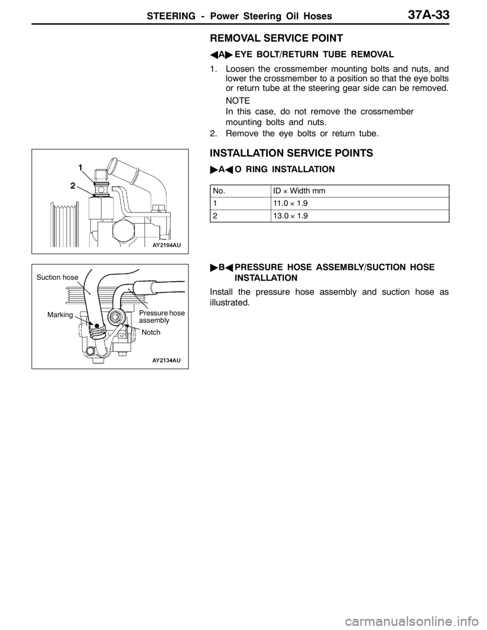
"AAO RING INSTALLATION
No.ID×Width mm
111.0×1.9
213.0×1.9
"BAPRESSURE HOSE ASSEMBLY/SUCTION HOSE
INSTALLATION
Install the pressure hose assembly and suction hose as
illustrated.
1
2
Suction hose
Pressure hose
assembly
Marking
Notch
Page 1148 of 1449

NOTES
Page 1149 of 1449

42-1
BODY
CONTENTS
HOOD2 .................................
ON-VEHICLE SERVICE 2..................
Adjustment of Clearance around Hood 2......
Adjustment of Alignment of Hood Stepped
Portion and Hood Striker 2..................
Adjustment of Hood Height 2.................
HOOD 3..................................
FENDER4 ..............................
SPECIAL TOOL 4.........................
FENDER 5................................
FUEL FILLER DOOR7 .................
STRUT TOWER BAR AND REAR END
CROSS BAR8 ...........................
WINDOW GLASS9 .....................
ADHESIVE 9..............................
SPECIAL TOOLS 9........................
WINDOW REPAIR 9.......................
WINDSHIELD 11...........................
REAR WINDOW GLASS 16................
DOORS19 ..............................
SERVICE SPECIFICATIONS 19.............ADHESIVES 19............................
SPECIAL TOOLS 19.......................
TROUBLESHOOTING 20...................
ON-VEHICLE SERVICE 20.................
Door Adjustment 20.........................
Door Window Glass Adjustment 21...........
Adjustment and Replacement during Power
Window Malfunction 22......................
Power Window Safety Mechanism Check 22..
Power Window Timer Function Check 22......
Door Outside Handle Looseness Check 23....
Power Window Operation Current Check 23...
Circuit Breaker Check 23....................
Power Window Check 23....................
Door Inside Handle Looseness Check and
Adjustment 24...............................
DOOR ASSEMBLY 25......................
DOOR TRIM AND
WATERPROOF FILM 27....................
DOOR GLASS AND REGULATOR 32.......
DOOR HANDLE AND LATCH 35...........
WINDOW GLASS RUNCHANNEL AND
DOOR OPENING WEATHERSTRIP 38.......
TRUNK LID41 ..........................
Page 1150 of 1449
BODY -Hood42-2
HOOD
ON - VEHICLE SERVICE
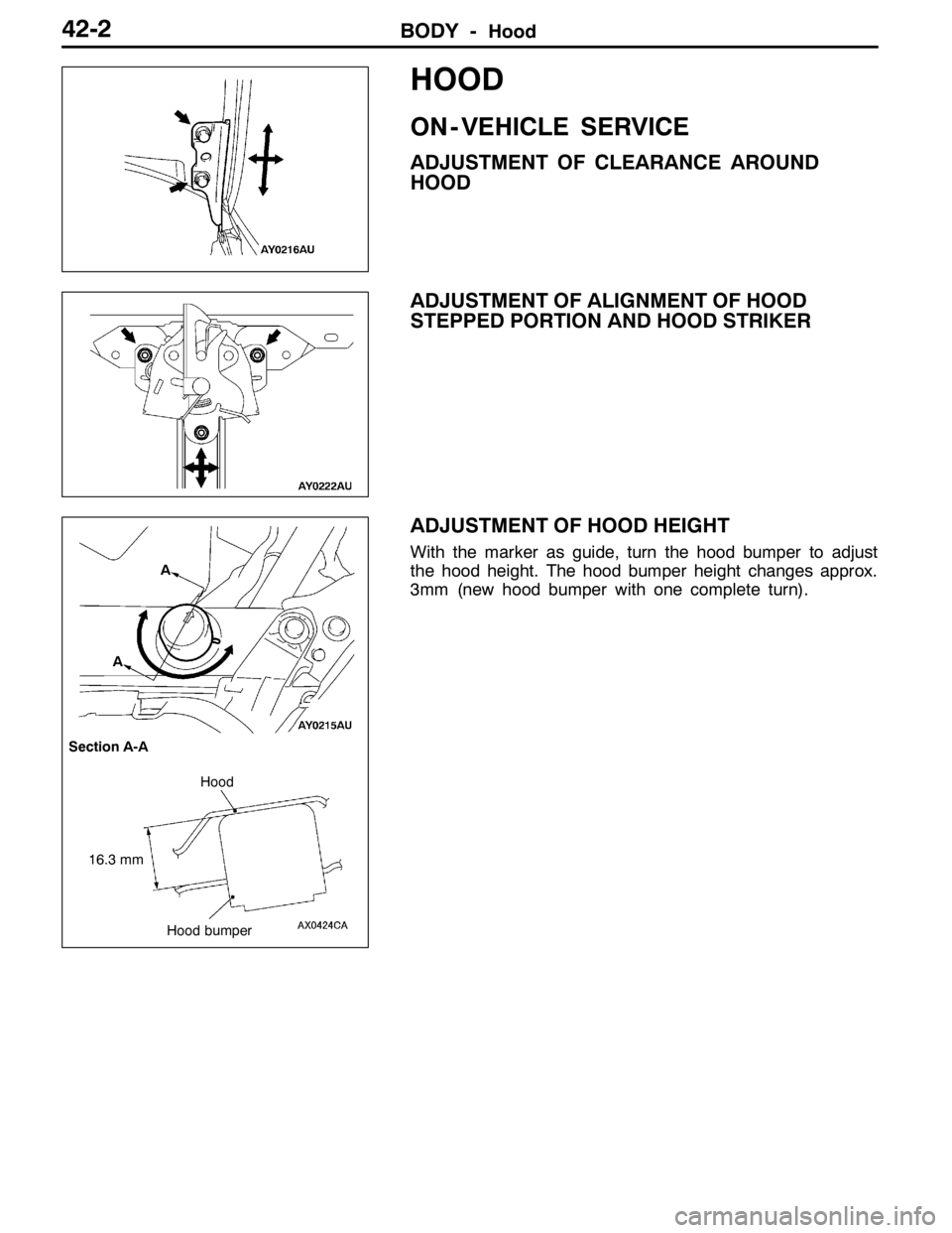
ADJUSTMENT OF CLEARANCE AROUND
HOOD
ADJUSTMENT OF ALIGNMENT OF HOOD
STEPPED PORTION AND HOOD STRIKER
ADJUSTMENT OF HOOD HEIGHT
With the marker as guide, turn the hood bumper to adjust
the hood height. The hood bumper height changes approx.
3mm (new hood bumper with one complete turn).
A
A
Section A-A
16.3 mmHood
Hood bumper