MITSUBISHI LANCER EVOLUTION 2007 Service Repair Manual
Manufacturer: MITSUBISHI, Model Year: 2007, Model line: LANCER EVOLUTION, Model: MITSUBISHI LANCER EVOLUTION 2007Pages: 1449, PDF Size: 56.82 MB
Page 1181 of 1449
BODY -Doors42-33
REMOVAL SERVICE POINTS
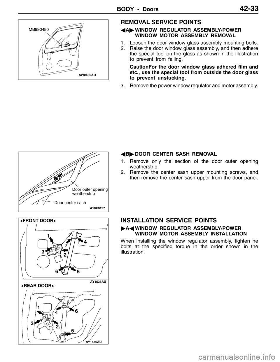
AA"WINDOW REGULATOR ASSEMBLY/POWER
WINDOW MOTOR ASSEMBLY REMOVAL
1. Loosen the door window glass assembly mounting bolts.
2. Raise the door window glass assembly, and then adhere
the special tool on the glass as shown in the illustration
to prevent from falling.
CautionFor the door window glass adhered film and
etc., use the special tool from outside the door glass
to prevent unstucking.
3. Remove the power window regulator and motor assembly.
AB"DOOR CENTER SASH REMOVAL
1. Remove only the section of the door outer opening
weatherstrip
2. Remove the center sash upper mounting screws, and
then remove the center sash upper from the door panel.
INSTALLATION SERVICE POINTS
"AAWINDOW REGULATOR ASSEMBLY/POWER
WINDOW MOTOR ASSEMBLY INSTALLATION
When installing the window regulator assembly, tighten he
bolts at the specified torque in the order shown in the
illustration.
MB990480
Door outer opening
weatherstrip
Door center sash
A18X0127
1
2 4
3
56
1
2
34
5 67
Page 1182 of 1449
BODY -DoorsBODY -Doors42-34
"BAOPERATION CHECK
1. Install the glass to the window regulator assembly.
Caution
(1) As fully open position which is programed in the
power window-ECU is released (initialized), the
window regulator assembly should not be
operated until it is installed to the glass.
(2) The clamping prevention function does not
operate the first time that the glass is fully closed.
2. Press the power window switch to fully-open the glass,
and then return the glass toward the fully-close position
about 30 mm each. In the fully-close position, keep on
pressing the power window switch for 0.5 second or more.
NOTE
This operation will program the power window-ECU.
INSPECTION
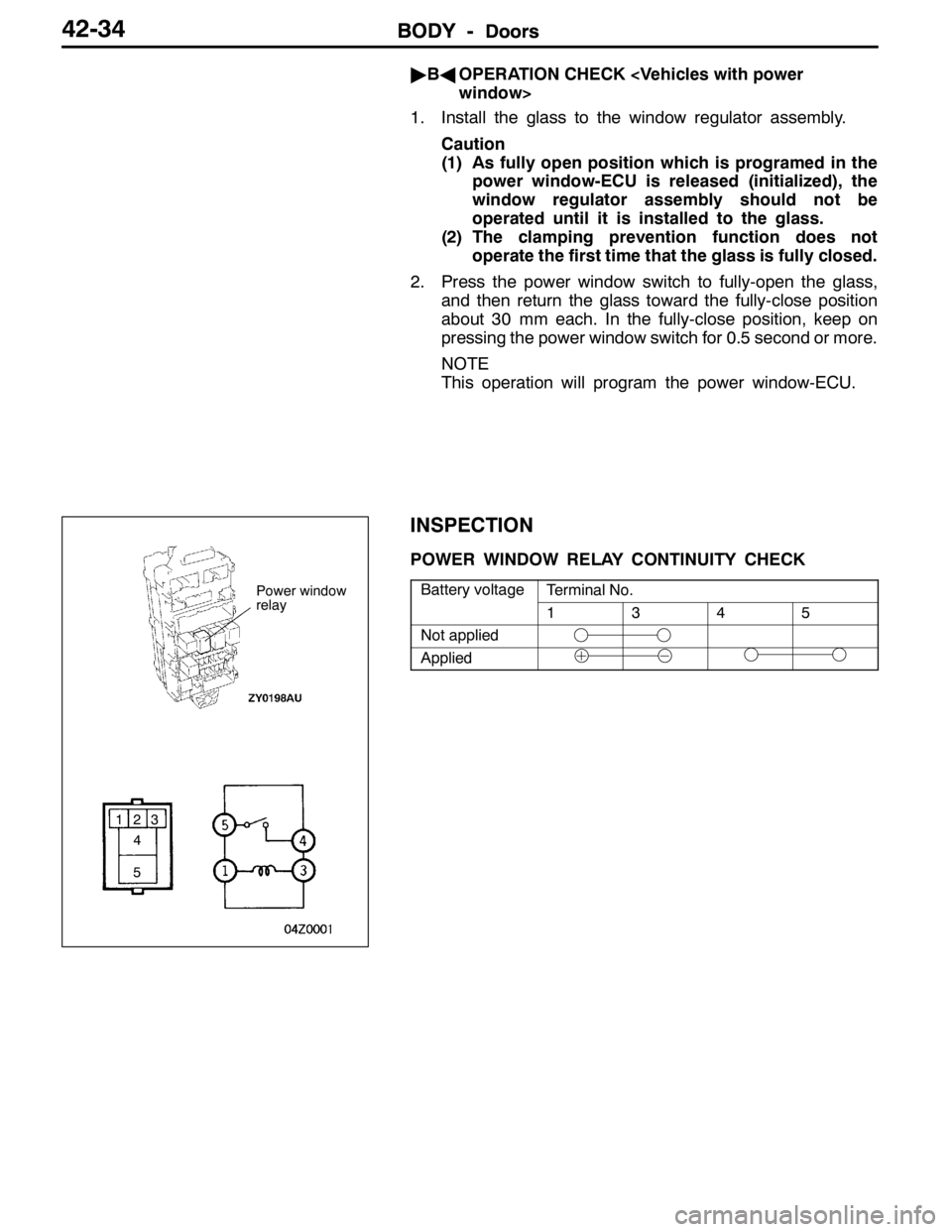
POWER WINDOW RELAY CONTINUITY CHECK
Battery voltageTerminal No.yg
1345
Not applied
Applied
Power window
relay
123
4
5
Page 1183 of 1449
BODY -Doors42-35
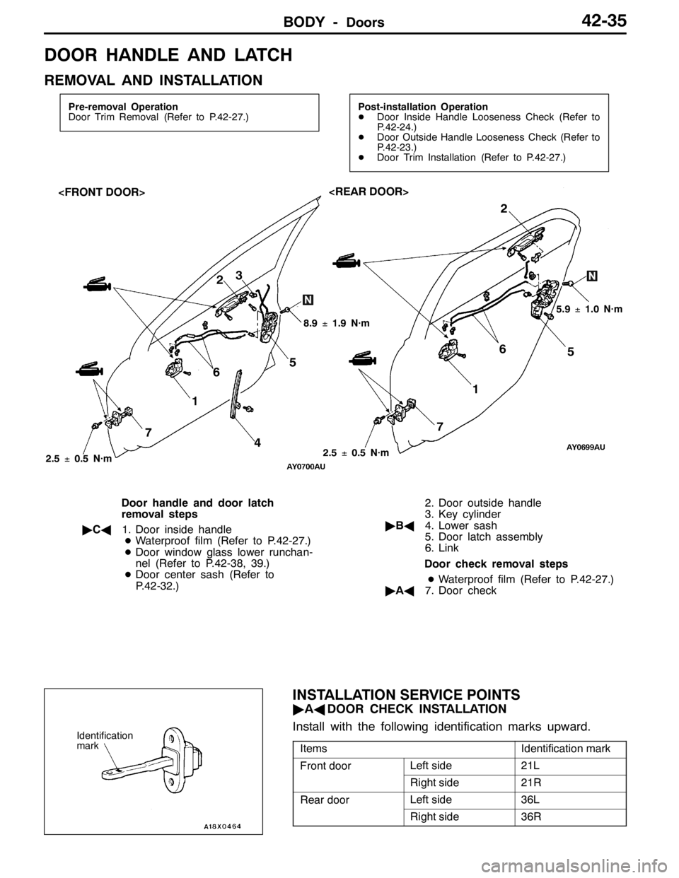
DOOR HANDLE AND LATCH
REMOVAL AND INSTALLATION
Pre-removal Operation
Door Trim Removal (Refer to P.42-27.)Post-installation Operation
DDoor Inside Handle Looseness Check (Refer to
P.42-24.)
DDoor Outside Handle Looseness Check (Refer to
P.42-23.)
DDoor Trim Installation (Refer to P.42-27.)
3
5
4 72
6
1
5.9±1.0 N·m
8.9±1.9 N·m
2
1
75 6
2.5±0.5 N·m
2.5±0.5 N·m
Door handle and door latch
removal steps
"CA1. Door inside handle
DWaterproof film (Refer to P.42-27.)
DDoor window glass lower runchan-
nel (Refer to P.42-38, 39.)
DDoor center sash (Refer to
P.42-32.)2. Door outside handle
3. Key cylinder
"BA4. Lower sash
5. Door latch assembly
6. Link
Door check removal steps
DWaterproof film (Refer to P.42-27.)
"AA7. Door check
INSTALLATION SERVICE POINTS
"AADOOR CHECK INSTALLATION
Install with the following identification marks upward.
ItemsIdentification mark
Front doorLeft side21L
Right side21R
Rear doorLeft side36L
Right side36R
Identification
mark
Page 1184 of 1449
BODY -DoorsBODY -Doors42-36
"BALOWER SASH INSTALLATION
Be sure to install the lower sash to the window rear sash
(at door) securely.
"CADOOR INSIDE HANDLE INSTALLATION
1. Install the inside lock cable to the door inside handle
as follows:
(1) Install the inner cable end in the inside lock cable
to the clip in the door inside handle.
(2) Turn the inside lock knob to the door lock position.
(3) Install the outer cable end to the door inside handle
securely.
(4) Install the clip to the inner cable.
2. Install the inside handle rod to the door inside handle.
3. Install the door inside handle to the door.
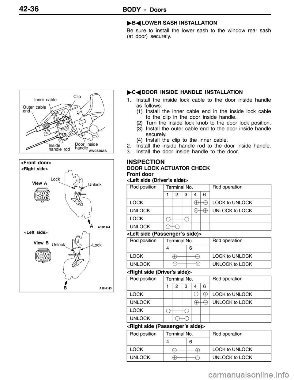
INSPECTION
DOOR LOCK ACTUATOR CHECK
Front door
Rod positionTerminal No.Rod operation
12346
LOCKLOCK to UNLOCK
UNLOCKUNLOCK to LOCK
LOCK
UNLOCK
Rod positionTerminal No.Rod operation
46
LOCKLOCK to UNLOCK
UNLOCKUNLOCK to LOCK
Rod positionTerminal No.Rod operation
12346
LOCKLOCK to UNLOCK
UNLOCKUNLOCK to LOCK
LOCK
UNLOCK
Rod positionTerminal No.Rod operationp
46
p
LOCKLOCK to UNLOCK
UNLOCKUNLOCK to LOCK
Door inside
handle
Inner cableClip
Outer cable
end
Inside
handle rod
B Unlock
View B
Lock
View A
Unlock Lock
A
Page 1185 of 1449
BODY -Doors42-37
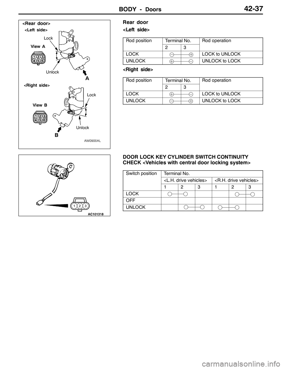
Rear door
Rod positionTerminal No.Rod operationp
23
p
LOCKLOCK to UNLOCK
UNLOCKUNLOCK to LOCK
Rod positionTerminal No.Rod operationp
23
p
LOCKLOCK to UNLOCK
UNLOCKUNLOCK to LOCK
DOOR LOCK KEY CYLINDER SWITCH CONTINUITY
CHECK
Switch positionTerminal No.p
123123
LOCK
OFF
UNLOCK
BA
View ALock
Unlock
View B
UnlockLock
Page 1186 of 1449

BODY -Doors42-38
WINDOW GLASS RUNCHANNEL AND DOOR OPENING
WEATHERSTRIP
REMOVAL AND INSTALLATION
2
5
43
1
Sectional view of
clip position Sectional view of clip
position
Section A - A
Door
5
A
A
Door inner opening weatherstrip
removal steps
DScuff plate (Refer to GROUP 52A.)
DCowl side trim (Refer to GROUP
52A.)
DCenter pillar lower trim (Refer to
GROUP 52A.)
1. Door inner opening weatherstrip
Door outer opening weatherstrip
removal
AA""AA2. Door outer opening weatherstrip
Door window glass runchannel
removal
3. Door window glass runchannelDoor beltline inner weatherstrip
removal steps
DDoor trim (Refer to P.42-27.)
4. Door beltline inner weatherstrip
Door beltline molding removal
steps
DOutside mirror (Refer to GROUP
51.)
DDoor window glass (Refer to
P.42-32.)
5. Door beltline molding
Page 1187 of 1449
BODY -Doors42-39
Sectional view of
clip positionSectional view of
clip position
5
4 3
21
Section A - A
Door
6
A
A
6
BB
Section B - B
Door
23
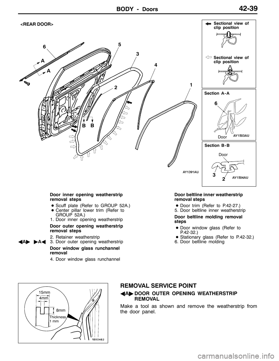
Door inner opening weatherstrip
removal steps
DScuff plate (Refer to GROUP 52A.)
DCenter pillar lower trim (Refer to
GROUP 52A.)
1. Door inner opening weatherstrip
Door outer opening weatherstrip
removal steps
2. Retainer weatherstrip
AA""AA3. Door outer opening weatherstrip
Door window glass runchannel
removal
4. Door window glass runchannelDoor beltline inner weatherstrip
removal steps
DDoor trim (Refer to P.42-27.)
5. Door beltline inner weatherstrip
Door beltline molding removal
steps
DDoor window glass (Refer to
P.42-32.)
DStationary glass (Refer to P.42-32.)
6. Door beltline molding
REMOVAL SERVICE POINT
AA"DOOR OUTER OPENING WEATHERSTRIP
REMOVAL
Make a tool as shown and remove the weatherstrip from
the door panel.15mm
4mm
8mm
Thickness
1mm
Page 1188 of 1449

BODY -Doors42-40
INSTALLATION SERVICE POINTS
"AADOOR OUTER OPENING WATHERSTRIP
INSTALLATION
The clip colour identifies the left and right weatherstrips so
be sure to use the colours as install correctly.
Applicable sideIdentification colour
Right doorPink
Left doorNatural (White)
Page 1189 of 1449

BODY -Trunk lid42-41
TRUNK LID
REMOVAL AND INSTALLATION
2
34 56
7 89 10
111
12A
A
B
B5 5
99
14Measure of
length mm
15
4 9
12
8.9±1.9 N·m
Section A - A
Section B - B
Trunk lid weatherstrip removal
steps
DRear end trim
GROUP 52A.)
"BA1. Trunk lid weatherstrip
Trunk lid release cable and trunk
lid release handle removal steps
DTrunk rear side trim (Left side)
(Refer to GROUP 52A.)
DRear seat (Refer to GROUP 52A.)
DCenter pillar lower trim (Refer to
GROUP 52A.)
DCowl side trim
DAccelerator pedal stopper
2. Trunk lid release handle
3. Trunk lid release cable
Trunk lid striker removal steps
DRear end trim
GROUP 52A.)4. Trunk lid striker
Trunk lid panel removal steps
5. Trunk lid bumper
6. Trunk lid lock cylinder
7. Trunk lid latch assembly
8. Trunk lid hinge mounting bolt
9. Trunk lid panel assembly
Trunk lid latch assembly removal
7. Trunk lid latch assembly
Trunk lid hinge removal steps
DRear shelf trim
DRear seat (Refer to GROUP 52A.)
9. Trunk lid panel assembly
AA""AA10. Trunk lid torsion bar (Right side)
AA""AA11. Trunk lid torsion bar (Left side)
12. Trunk lid hinge
Page 1190 of 1449
BODY -Trunk lid42-42
Grease application area
67
2
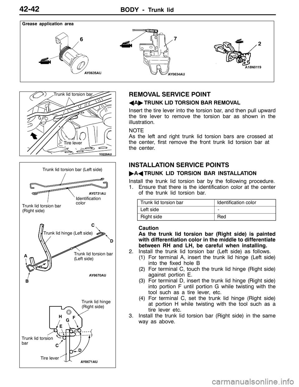
REMOVAL SERVICE POINT
AA"TRUNK LID TORSION BAR REMOVAL
Insert the tire lever into the torsion bar, and then pull upward
the tire lever to remove the torsion bar as shown in the
illustration.
NOTE
As the left and right trunk lid torsion bars are crossed at
the center, first remove the front trunk lid torsion bar at
the center.
INSTALLATION SERVICE POINTS
"AATRUNK LID TORSION BAR INSTALLATION
Install the trunk lid torsion bar by the following procedure.
1. Ensure that there is the identification color at the center
of the trunk lid torsion bar.
Trunk lid torsion barIdentification color
Left side-
Right sideRed
Caution
As the trunk lid torsion bar (Right side) is painted
with differentiation color in the middle to differentiate
between RH and LH, be careful when installing.
2. Install the trunk lid torsion bar (Left side) as follows.
(1) For terminal A, insert the trunk lid hinge (Left side)
into the fixed hole B
(2) For terminal C, touch the trunk lid hinge (Right side)
against portion E.
(3) For terminal D, insert the trunk lid hinge (Right side)
into portion F until portion G while twisting with the
tool such as a tire lever, etc.
(4) For terminal C, set the trunk lid hinge (Right side)
at portion H while twisting with the tool such as a
tire lever etc.
3. Install the trunk lid torsion bar (Right side) in the same
way as above.
Trunk lid torsion bar
Tire lever
Tire lever
D
Trunk lid torsion
bar
H
Identification
color
Trunk lid torsion bar
(Right side)
Trunk lid torsion bar
(Left side) Trunk lid hinge (Left side)
A
BC
D
Trunk lid hinge
(Right side)
C
F
G
E
Trunk lid torsion bar (Left side)