MITSUBISHI LANCER EVOLUTION 2007 Service Repair Manual
LANCER EVOLUTION 2007
MITSUBISHI
MITSUBISHI
https://www.carmanualsonline.info/img/19/57084/w960_57084-0.png
MITSUBISHI LANCER EVOLUTION 2007 Service Repair Manual
Trending: jacking points, automatic transmission fluid, jacking, Engine oil cooler gasket, charging, Engine oil pump, battery location
Page 1211 of 1449

EXTERIOR -Windshield Wiper and Washer51-19
WINDSHIELD WIPER AND WINDSHIELD WASHER
SWITCH AND WINDSHIELD INTERMITTENT WIPER
INTERVAL ADJUSTING KNOB CHECK
(1) Windshield wiper and washer switch, rear wiper and
washer switch.
Switch positionTerminal No.p
6789101167891011
OFF
Windshield wiper mist switch ON
Windshield intermittent wiper switch ON
Windshield low-speed wiper switch ON
Windshield high-speed wiper switch ON
Windshield washer switch ON
(2) Windshield intermittent wiper interval adjusting knob
Measure the resistance value at terminal numbers 3 and
6. The resistance value should rise smoothly from
approximately 0Ω(“FAST” position) to apporoximately
1kΩ(“SLOW” position).
WINDSHIELD INTERMITTENT WIPER INTERVAL
ADJUSTING KNOB CHECK
Measure the resistance value at terminal numbers 4 and
6. The resistance value should rise smoothly from
approximately 0 W (“FAST” position) to approximately 1 kW
(“SLOW” position).
NOTE
The windshield washer switch and windshield wiper switch
is integrated in the column-ECU, so can not be checked as
an individual part. However, its operation can be checked
by the input signal check. (GROUP 54B - Troubleshooting.)
Page 1212 of 1449
EXTERIOR -Marks51-20
MARKS
REMOVAL AND INSTALLATION
2
3
45
1
1. Three-diamond mark
"
AA2. Three-diamond mark
"
AA3. Evolution - VII mark"
AA4. LANCER mark
"
AA5. RECARO decal
INSTALLATION SERVICE POINT
"AAATTACHMENT OF EACH MARK
1. ATTACHED POSITION
Page 1213 of 1449
EXTERIOR -Marks51-21
(2) Three - diamond mark, (3) Evolution - VII mark
Press line 73 mm
23 mm
73 mm
134 mm
204 mm
247 mm 8.5 mmPress line
Press line
View A
AB
Vehicle centerline
Press line Press line
Three - diamond
mark 73 mmC C
Section C - C
Vehicle centerline
14 mm
225 mm58 mm
97 mm
151 mm8.5 mm
3.5 mm
Press line
View BVehicle centerline
(4) Lancer mark
20±1mm 30±1mm
Trunk lid terminal
Page 1214 of 1449
EXTERIOR -Marks51-22
(5) RECARO decal
RECARO decal terminal
52 mm
Stationary window
weather strip terminal 15 mm31 mm
16 mm
RECARO decal terminal
16 mm 19 mm28 mm
52 mm Stationary
window glass
Stationary window
weather strip terminalStationary
window glass
Application tape terminalApplication tape terminal
2. Installation steps
(1) Remove grease on the marked surface of the
body with unlead gasoline.
(2) Peel off the protection sheet on the back of the
mark to paste it on the installation position.
Caution
1) Carry out the operation in a dust-free place where
the room temperature is between 20 and 38.
2) If the room temperature is below 20, heat the mark
and the body (pasted area) between 20 and 30.
3) Be sure to pressure the mark immediately after
the pasting is done.
Page 1215 of 1449
EXTERIOR -Outside Mirror51-23
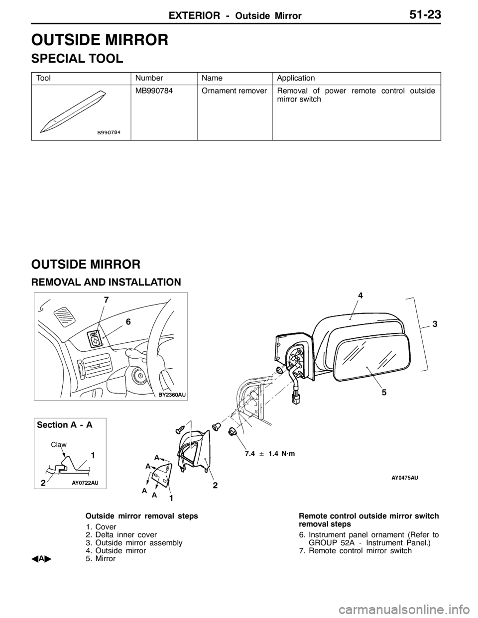
OUTSIDE MIRROR
SPECIAL TOOL
ToolNumberNameApplication
MB990784Ornament removerRemoval of power remote control outside
mirror switch
OUTSIDE MIRROR
REMOVAL AND INSTALLATION
123 4
6 7
1
Claw
A
A
Section A - A5
AA
2
7.4±1.4 N·m
Outside mirror removal steps
1. Cover
2. Delta inner cover
3. Outside mirror assembly
4. Outside mirror
A
A"5. MirrorRemote control outside mirror switch
removal steps
6. Instrument panel ornament (Refer to
GROUP 52A - Instrument Panel.)
7. Remote control mirror switch
Page 1216 of 1449
EXTERIOR -Outside MirrorEXTERIOR -Outside Mirror51-24
REMOVAL SERVICE POINT
AA"MIRROR REMOVAL
Tilt the mirror upward, insert the flat-tipped screw driver
wrapped around with the protection tape between the notch
located behind the mirror and pivot plate, and pry off the
mirror.
INSPECTIONS
REMOTE CONTROLLED MIRROR ASSEMBLY CHECK
Battery connection terminalOperation of mirror
123
Up
Down
Right
Left
THERMAL PRINTED WIRE FUNCTION CHECK
For vehicles with thermal printed wires, check that there is
continuity between terminals (1) and (4).
Section A – A
Notch Flat-tipped
screw driver
Pivot plate
AMirrorFlat-tipped screw driverA
Page 1217 of 1449
EXTERIOR -Outside Mirror51-25
CONTINUITY INSPECTION OF POWER REMOTE
CONTROL MIRROR SWITCH
SwitchSwitch positionTerminal numberp
LeftRight
169101112369
Mirror adjustment switchUp
Down
Left
Right
Page 1218 of 1449
Page 1219 of 1449
INTERIOR 52A......................................................
SUPPLEMENTAL RESTRAINT SYSTEM (SRS) 52B.....................
52A-1
INTERIOR AND
SUPPLEMENTAL
RESTRAINT
SYSTEM (SRS)
CONTENTS
Page 1220 of 1449

52A-2
INTERIOR
CONTENTS
SPECIAL TOOL 3............................
INSTRUMENT PANEL* 3......................
FRONT FLOOR CONSOLE 10................
REAR FLOOR CONSOLE 12..................
TRIMS 15....................................
HEADLINING 17..............................SEAT 19.....................................
Front Seat 19..................................
Rear Seat 22..................................
SEAT BELT 25...............................
Front Seat Belt 25.............................
Rear Seat Belt 26..............................
WARNINGS REGARDING SERVICING OF SUPPLEMENTAL RESTRAINT SYSTEM (SRS) EQUIPPED VEHICLES
WARNING!
(1) Improper service or maintenance of any component of the SRS, or any SRS-related component, can lead to personal
injury or death to service personnel (from inadvertent firing of the air bag) or to the driver and passenger (from rendering
the SRS inoperative).
(2) Service or maintenance of any SRS component or SRS-related component must be performed only at an authorized
MITSUBISHI dealer.
(3) MITSUBISHI dealer personnel must thoroughly review this manual, and especially its GROUP 52B - Supplemental
Restraint System (SRS) before beginning any service or maintenance of any component of the SRS or any SRS-related
component.
NOTE
The SRS includes the following components: SRS-ECU, SRS warning lamp, air bag module, clock spring and interconnecting
wiring. Other SRS-related components (that may have to be removed/installed in connection with SRS service or maintenance) are
indicated in the table of contents by an asterisk (*).
Trending: radio antenna, open gas tank, brake pads replacement, transmission, tow bar, transmission fluid, compression ratio


