MITSUBISHI SPYDER 1990 Service Repair Manual
Manufacturer: MITSUBISHI, Model Year: 1990, Model line: SPYDER, Model: MITSUBISHI SPYDER 1990Pages: 2103, PDF Size: 68.98 MB
Page 1071 of 2103
AUTOMATIC TRANSAXLE
ENGINE (TURBO) AND ENGINE> On-vehicle Service
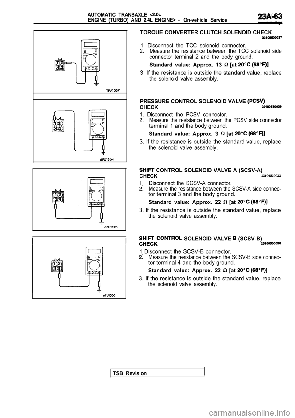
TORQUE CONVERTER CLUTCH SOLENOID CHECK
1. Disconnect the TCC solenoid connector.
2.Measure the resistance between the TCC solenoid side
connector terminal 2 and the body ground.
Standard value: Approx. 13 [at
3. If the resistance is outside the standard value, replace
the solenoid valve assembly.
PRESSURE CONTROL SOLENOID VALVE
CHECK
1. Disconnect the PCSV connector.
2.Measure the resistance between the PCSV side connec tor
terminal 1 and the body ground.
Standard value: Approx. 3 [at
3. If the resistance is outside the standard value, replace
the solenoid valve assembly.
CONTROL SOLENOID VALVE A (SCSV-A)
CHECK23100520033
1Disconnect the SCSV-A connector.
Measure the resistance between the SCSV-A side conn ec-
tor terminal 3 and the body ground.
Standard value: Approx. 22 [at
3. If the resistance is outside the standard value, replace
the solenoid valve assembly.
SOLENOID VALVE (SCSV-B)
1 Disconnect the SCSV-B connector.
Measure the resistance between the SCSV-B side conn ec-
tor terminal 4 and the body ground.
Standard value: Approx. 22 [at
3. If the resistance is outside the standard value, replace
the solenoid valve assembly.
TSB Revision
Page 1072 of 2103
AUTOMATIC TRANSAXLE
ENGINE (TURBO) AND On-vehicle Service
Stall test consists of determining maximum engine speed
obtained at full throttle in positions. This test
checks torque converter overrunning clutch operation,
and holding ability of transmission clutches and
brake.
Caution
During this test, make sure no stands in front
of, or behind, vehicle.
1.Check the transmission fluid level, fluid temperatu re and
coolant temperature.
lFluid level: At “HOT” position on dipstick
l Fluid temperature:
lEngine coolant temperature:
2. Apply chocks to both rear wheels.
3.
engine tachometer.
4. Apply parking and service brakes fully.
5 . S t a r t e n g i n e .
6. With selector lever in position, depress accelerator
pedal fully to read engine
rpm. Do not hold
throttle wide open any longer than is necessary to obtain
maximum engine rpm reading, and never longer
5 seconds at a time. If more than one stall test is required,
operate at approximately 1,000 in neutral
for 2 minutes to cool transmission fluid between te sts.
Standard value:
TSB Revision
2,100 2,600
3 , 3 0 0 3 , 6 0 0
7.Place selector lever to position and perform test
by the same procedures above.
Stall Speed Above Specification in
If stall speed is higher than Specification, rear c lutch or overrun-
ning clutch is slipping. In this case, perform hydrau-
lic test to locate cause of slippage.
Stall Above Specification in “R”
If stall speed is higher than front clutch of trans-
axle or low-reverse brake is In this perform
hydraulic test to locate cause of slippage.
Stall Speed Above Specification and “R”
If stall speed is lower than insufficient engine
output or faulty torque converter is Check for en-
gine misfiring, ignition timing, valve clearance etc. If these
are good, torque converter is faulty..
Page 1073 of 2103
AUTOMATIC TRANSAXLE
ENGINE (TURBO) AND ENGINE> On-vehicle
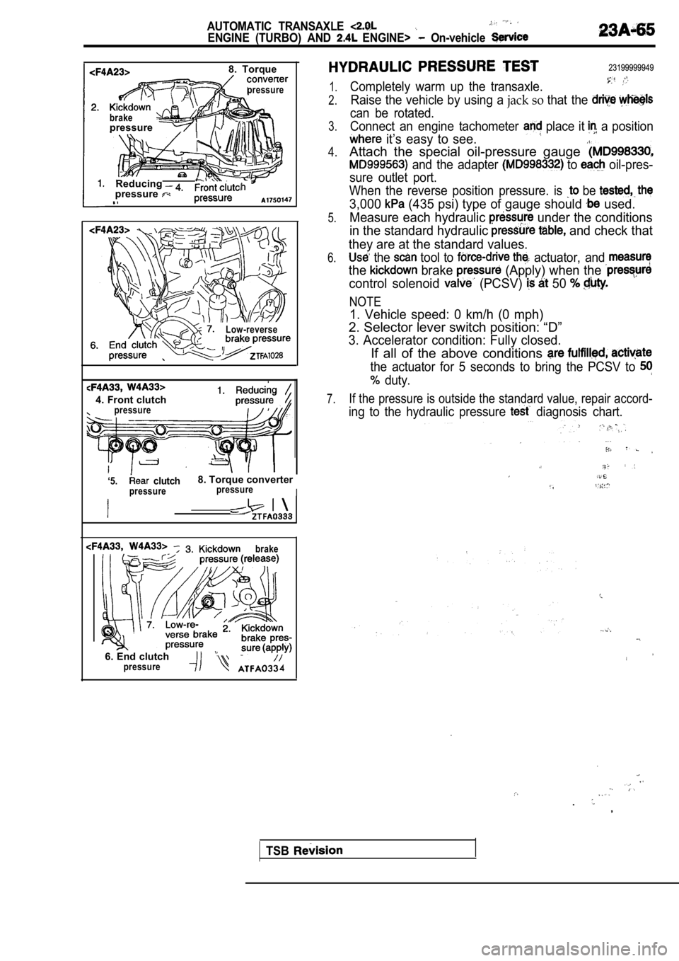
8. Torque
pressure
brakepressure
Reducingpressure
Low-reverse
4. Front clutchpressure
‘5. clutch8. Torque converter
pressurepressureI
brake
6. End clutch
23199999949
1.
2.
3.
4.
5.
6.
7.
Completely warm up the transaxle.
Raise the vehicle by using a jack so that the
can be rotated.
Connect an engine tachometer
place it a position
it’s easy to see.
Attach the special oil-pressure gauge
and the adapter to oil-pres-
sure outlet port.
When the reverse position pressure. is
be
3,000 (435 psi) type of gauge should used.
Measure each hydraulic
under the conditions
in the standard hydraulic
and check that
they are at the standard values.
the tool to actuator, and
the brake (Apply) when the
control solenoid (PCSV) 50
NOTE
1. Vehicle speed: 0 km/h (0 mph)
2. Selector lever switch position: “D”
3. Accelerator condition: Fully closed.
If all of the above conditions
the actuator for 5 seconds to bring the PCSV to
duty.
If the pressure is outside the standard value, repa ir accord-
ing to the hydraulic pressure diagnosis chart.
.
.
,
pressure
TSB
Page 1074 of 2103
TRANSAXLE
ENGINE AND ENGINE> On-vehicle Service
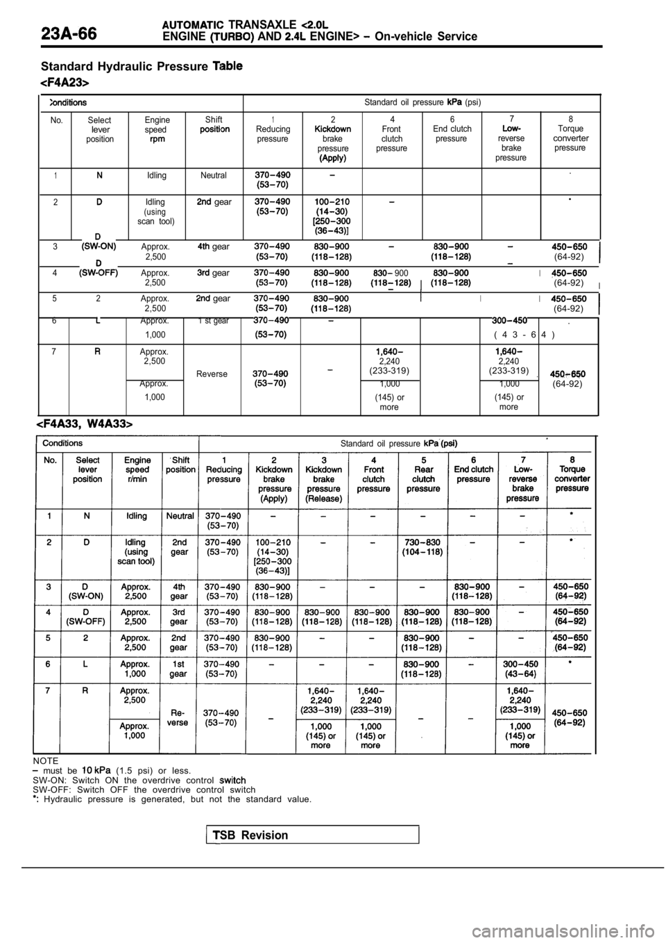
Standard Hydraulic Pressure
No. SelectleverpositionEngine
speed
Shift1Reducing
pressure Standard oil pressure
(psi)
24678Front
End clutchTorque
brake clutch pressurereverseconverterpressurepressure brakepressurepressure
1Idling Neutral.
2Idling gearl
(usingscan tool)
3Approx.gear2,500(64-92)
4Approx.gear 9002,500I(64-92)I
5 2Approx.gear2,500II(64-92)
6Approx.1 st gear.
1,000( 4 3 - 6 4 )
7Approx.2,500
2,240 2,240(233-319)Reverse(233-319).Approx.1,000 1,000(64-92)
1,000(145) or(145) or
more more
Standard oil pressure
NOTE must be (1.5 psi) or less.
SW-ON: Switch ON the overdrive control
SW-OFF: Switch OFF the overdrive control switch Hydraulic pressure is generated, but not the stand ard value.
TSB Revision
Page 1075 of 2103
AUTOMATIC TRANSAXLE ENGINE AND ENGINE> On-vehicle Service
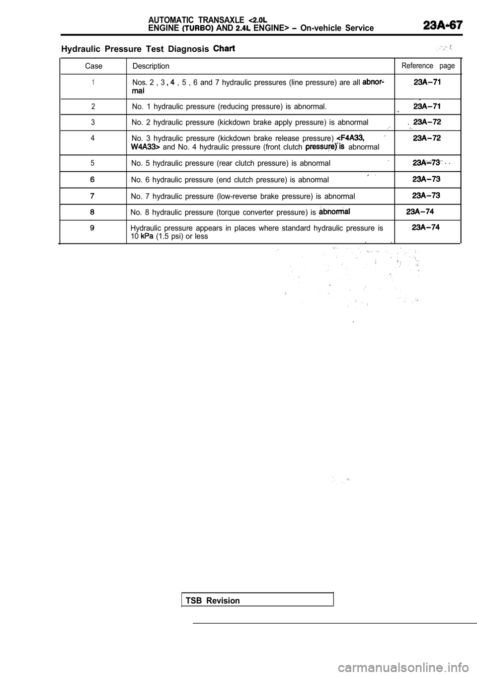
Hydraulic Pressure Test Diagnosis
Case
1
Description
Nos. 2 , 3
, 5 , 6 and 7 hydraulic pressures (line pressure) are all
Reference page
2No. 1 hydraulic pressure (reducing pressure) is abn ormal.
3
4
5
No. 2 hydraulic pressure (kickdown brake apply pres sure) is abnormal.
No. 3 hydraulic pressure (kickdown brake release pressure)
and No. 4 hydraulic pressure (front clutch abnormal
No. 5 hydraulic pressure (rear clutch pressure) is abnormal
. .
No. 6 hydraulic pressure (end clutch pressure) is a bnormal
No. 7 hydraulic pressure (low-reverse brake pressur e) is abnormal
No. 8 hydraulic pressure (torque converter pressure) is
Hydraulic pressure appears in places where standard hydraulic pressure is
10 (1.5 psi) or less. .
TSB Revision
Page 1076 of 2103
AUTOMATIC TRANSAXLE
ENGINE (TURBO) AND ENGINE> On-vehicle
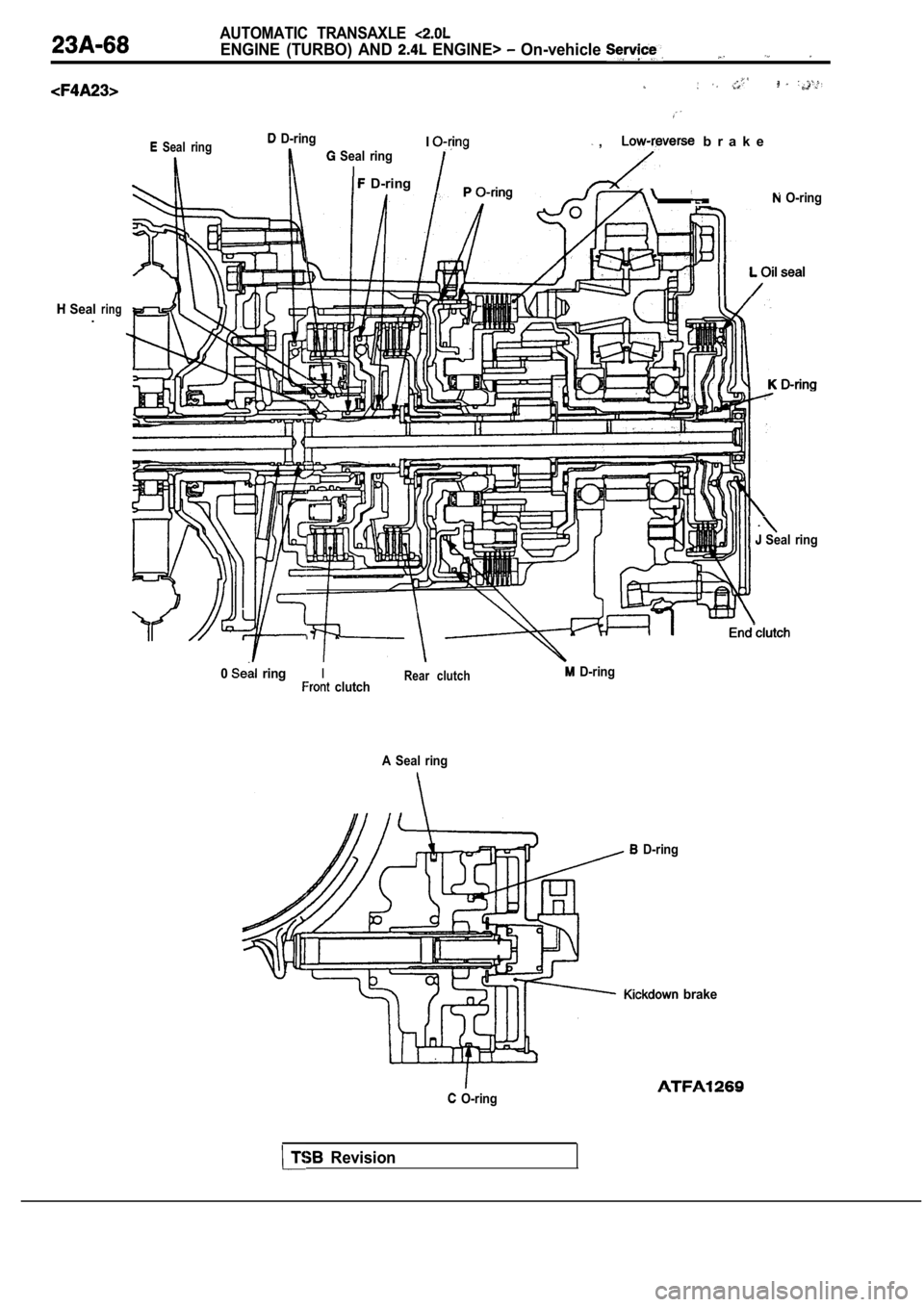
Seal ring D-ringI Seal ring
I
Seal.ring
D-ring
b r a k e
,
O-ring
Seal ring
0 ringIRear clutch D-ring clutch
A Seal ring
D-ring
brake
O-ring
Revision
Page 1077 of 2103
AUTOMATIC TRANSAXLE
ENGINE (TURBO) AND ENGINE> Service
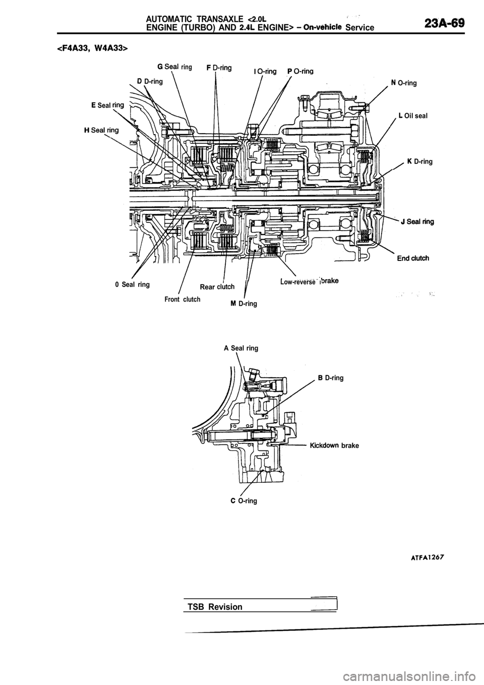
ringI
D-ring
Seal
O-ring
Oil seal
D-ring
0 Seal ring
RearLow-reverseI
Front clutch D-ring
A Seal ring
D-ring
brake
O-ring
TSB Revision
Page 1078 of 2103
AUTOMATIC: TRANSAXLE
ENGINE AND ENGINE> .
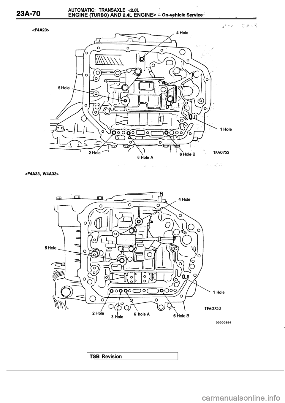
Hole
6 Hole A
Revision
1 Hole
2I3 Hole6 hole A
00000394
Page 1079 of 2103
AUTOMATIC TRANSAXLE
ENGINE (TURBO) AND ENGINE> On-vehicle Service
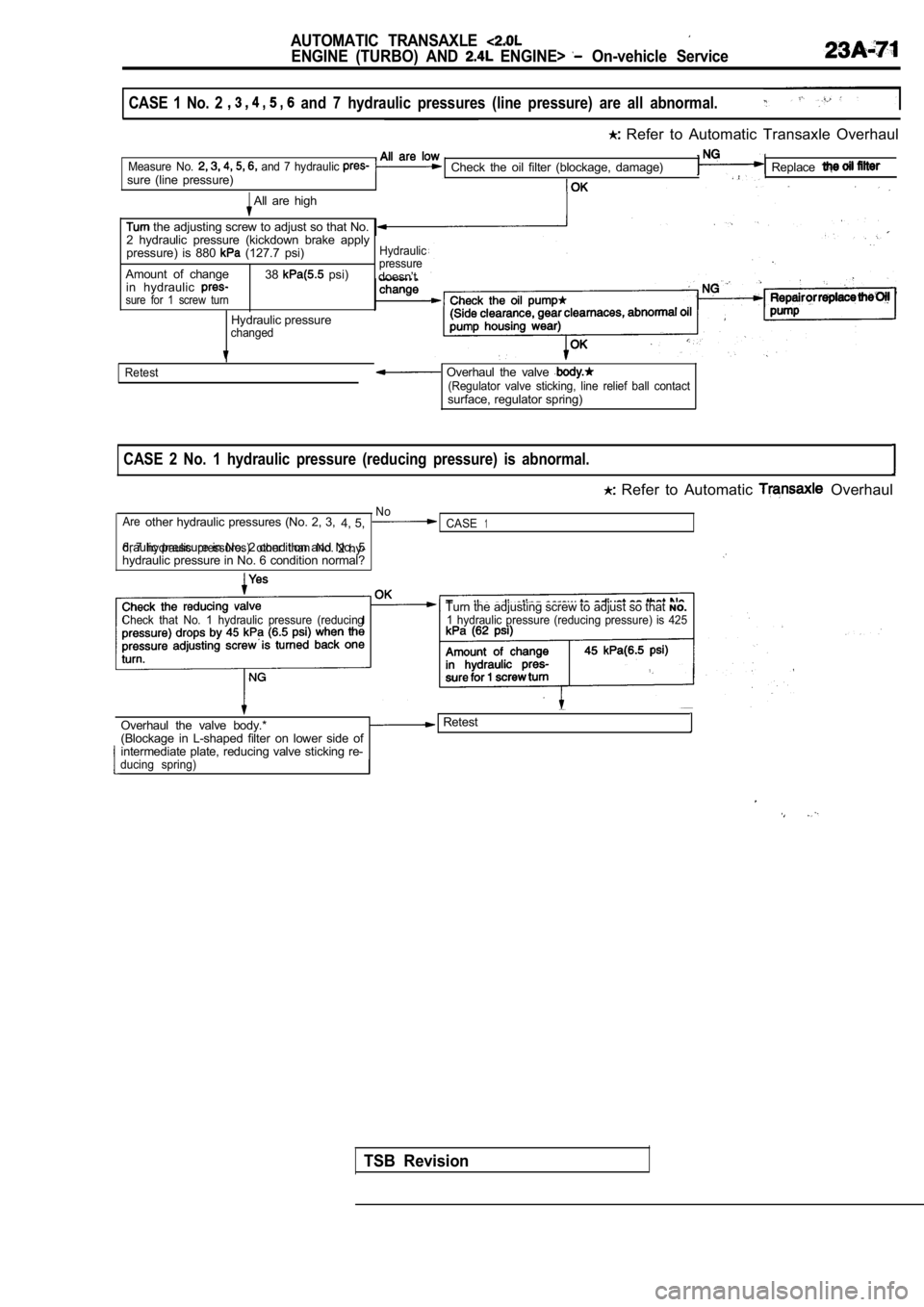
CASE 1 No. 2 and 7 hydraulic pressures (line pressure) are all abnormal.
Refer to Automatic Transaxle Overhaul
Measure No. and 7 hydraulic sure (line pressure)Check the oil filter (blockage, damage)Replace
All are high
the adjusting screw to adjust so that No.
2 hydraulic pressure (kickdown brake apply
pressure) is 880
(127.7 psi)Hydraulic
38 psi)pressureAmount of change doesn’t
in hydraulic
sure for 1 screw turn
Hydraulic pressurechanged
Retest
Overhaul the valve (Regulator valve sticking, line relief ball contactsurface, regulator spring)
CASE 2 No. 1 hydraulic pressure (reducing pressure) is abnormal.
Refer to Automatic Overhaul
No
Areother hydraulic pressures (No. 2, 3, 4, 5,CASE1
6, 7hydraulic pressures) other than No.2 hy-
draulic pressure in No. 2 condition and No. 5hydraulic pressure in No. 6 condition normal?
Check that No. 1 hydraulic pressure (reducingTurn the adjusting screw to adjust so that
NO.1 hydraulic pressure (reducing pressure) is 425
Overhaul the valve body.* Retest
(Blockage in L-shaped filter on lower side of
intermediate plate, reducing valve sticking re-
ducing spring)
TSB Revision
Page 1080 of 2103
AUTOMATIC: TRANSAXLE
ENGINE AND On-vehicle Service
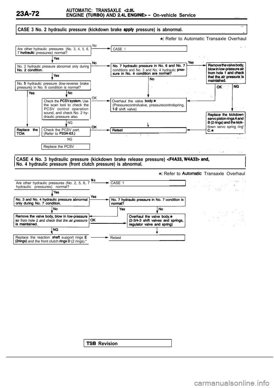
CASE 3 No. 2 hydraulic pressure (kickdown brake pressure) is abnormal. .
Refer to Automatic Transaxle Overhaul
NoAreotherhydraulic pressures(No.3, 4,5,6,CASE17 pressures) normal?
No. 2 hydraulic pressure abnormal only during
conditions and No. 3 and No. 4 hydraulic
No. hydraulic pressure (low-reverse brake
pressure) in No. 6 condition is normal?
Check the Usethe scan tool to check the
PCSV control operation
sound, and check No. 2 hy-
draulic pressure also.
NG
OK Overhaul the valve (Pressurecontrolvalve, pressurecontrolspring, shift valve)
I
Check the PCSV part.
(Refer to
,down servo spring ring
NG
Replace the PCSV
CASE 4 No. 3 hydraulic pressure (kickdown brake rel ease pressure)
No. 4 hydraulic pressure (front clutch pressure) is abnormal.
Refer to Transaxle Overhaul
N oAre other hydraulic pressures (No. 2, 5, 6, 7 CASE 1
hydraulic pressures) normal?
air from hole 2 and check that the air pressure
and the front clutch (2 rings).*
Replace the reaction support rings , Retest
Revision