MITSUBISHI SPYDER 1990 Service Repair Manual
SPYDER 1990
MITSUBISHI
MITSUBISHI
https://www.carmanualsonline.info/img/19/57345/w960_57345-0.png
MITSUBISHI SPYDER 1990 Service Repair Manual
Trending: tow, stop start, lights, compression ratio, automatic transmission, wheel, OBD port
Page 1371 of 2103
A U T O M A T I C T R A N S A X L E ,
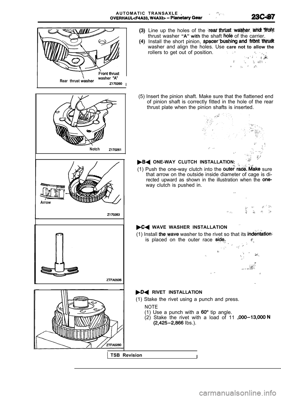
Rear thrustwasher
I
Notch
Arrow
Line up the holes of the
thrust washer “A” with the shaft of the carrier.
Install the short pinion,
washer and align the holes. Use care not to allow the
rollers to get out of position.
,
(5) Insert the pinion shaft. Make sure that the fla ttened end
of pinion shaft is correctly fitted in the hole of the rear
thrust plate when the pinion shafts is inserted.
ONE-WAY CLUTCH INSTALLATION:
(1) Push the one-way clutch into the sure
that arrow on the outside inside diameter of cage i s di-
rected upward as shown in the illustration when the
way clutch is pushed in.
WAVE WASHER INSTALLATION
(1) Install washer to the rivet so that its
is placed on the outer race
RIVET INSTALLATION
(1) Stake the rivet using a punch and press.
NOTE
(1) Use a punch with a tip angle.
(2) Stake the rivet with a load of 11
Ibs.).
TSB RevisionI
Page 1372 of 2103
AUTOMATIC TRANSAXLE
Gear and Transfer Drive Gear Set
GEAR AND TRANSFER DRIVE GEAR SET
DISASSEMBLY AND REASSEMBLY
8
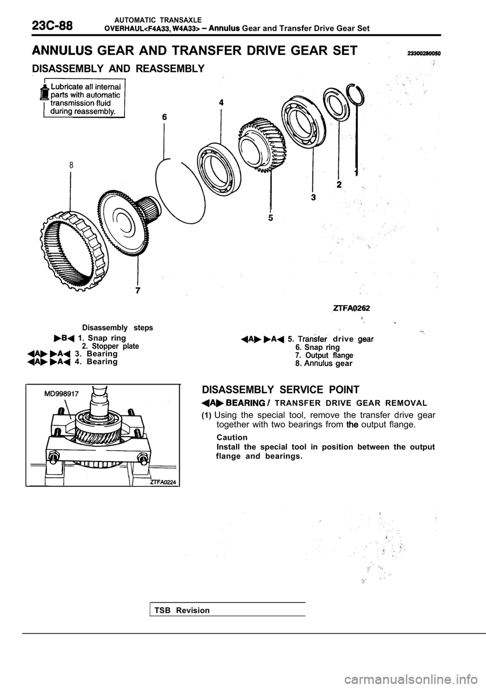
Disassembly steps
1. Snap ring2. Stopper plate 3. Bearing 4. Bearing
.
5. drive
6. Snap ring7. Output flange8. gear
DISASSEMBLY SERVICE POINT
TRANSFER DRIVE GEAR REMOVAL
(1) Using the special tool, remove the transfer drive g ear
together with two bearings from
output flange.
Caution
Install the special tool in position between the ou tput
flange and bearings.
TSB Revision
Page 1373 of 2103
AUTOMATIC TRANSAXLE
and Drive Gear Set
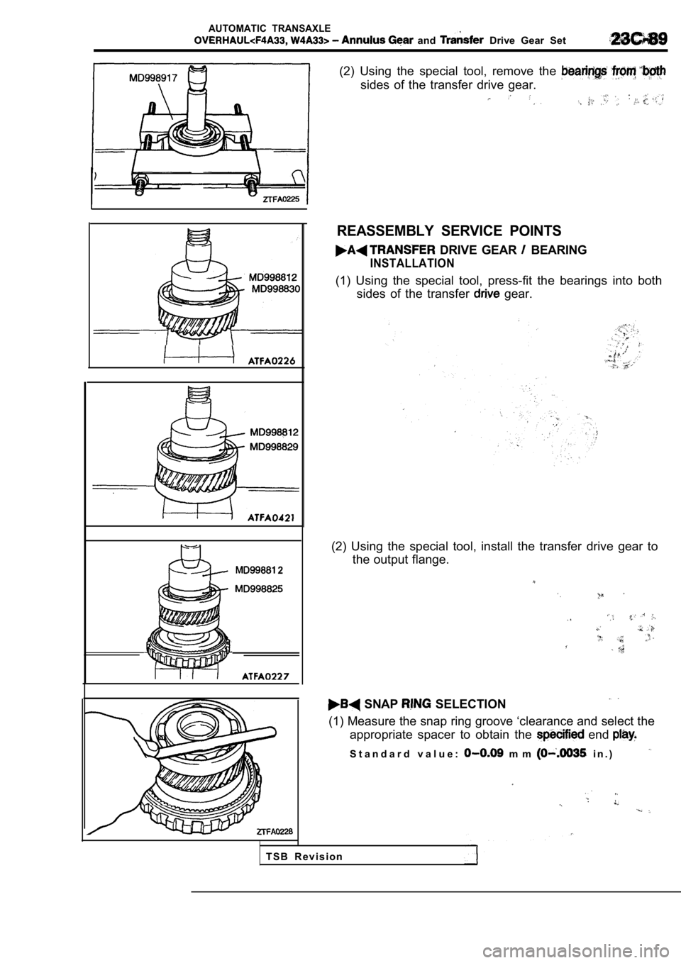
(2) Using the special tool, remove the
sides of the transfer drive gear.
2
REASSEMBLY SERVICE POINTS
DRIVE GEAR BEARING
INSTALLATION
(1) Using the special tool, press-fit the bearings into both
sides of the transfer
gear.
(2) Using the special tool, install the transfer dr ive gear to
the output flange.
SNAP SELECTION
(1) Measure the snap ring groove ‘clearance and sel ect the
appropriate spacer to obtain the
end
S t a n d a r d v a l u e : m m i n . )
T S B R e v i s i o n
Page 1374 of 2103
AUTOMATIC TRANSAXLE
Differential
DIFFERENTIAL23300310063
DISASSEMBLY AND REASSEMBLY
8
parts with automatic,
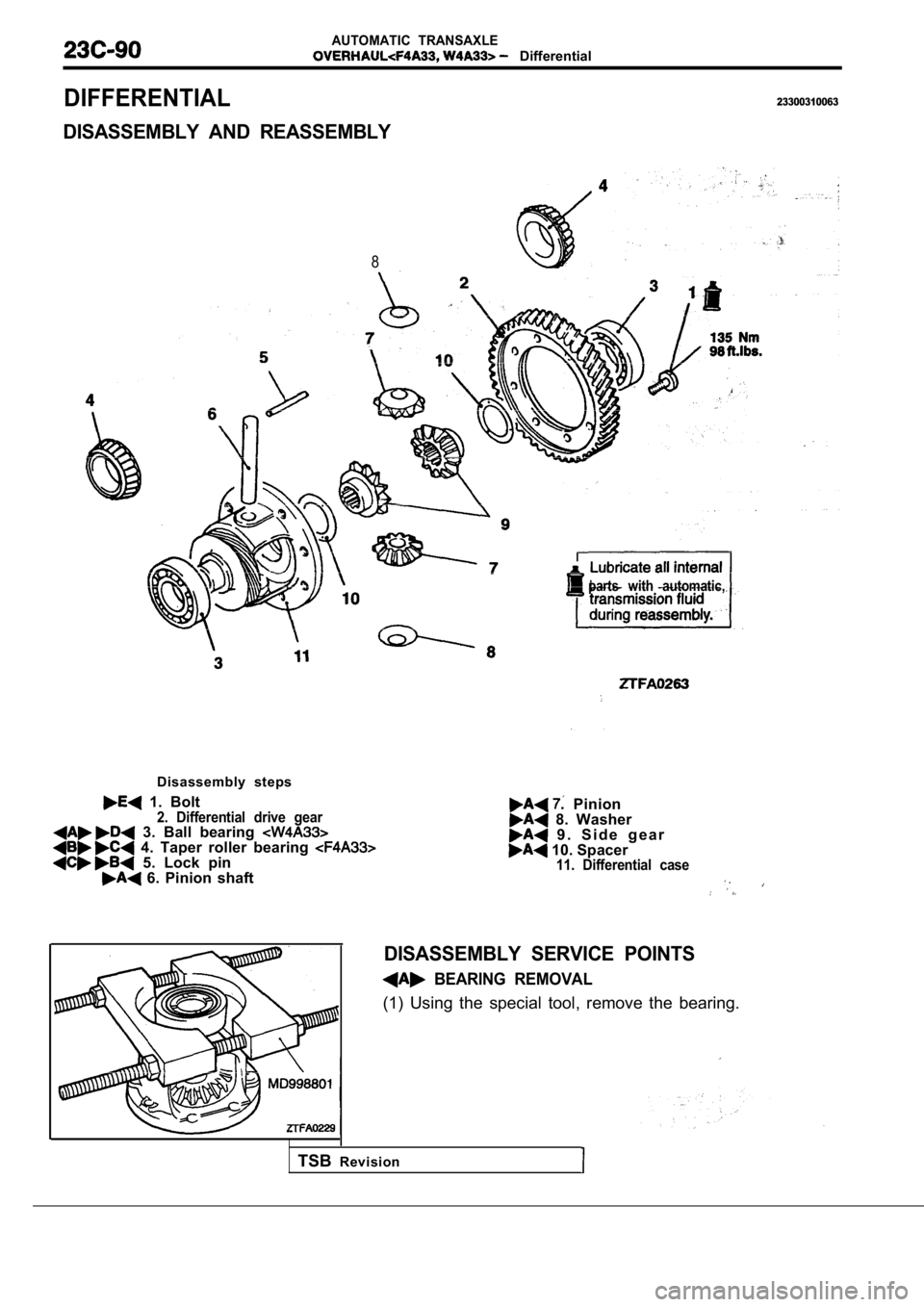
Disassembly steps
1. Bolt2. Differential drive gear 3. Ball bearing 4. Taper roller bearing 5. Lock pin 6. Pinion shaft
Pinion 8. Washer 9 . S i d e g e a r 10. Spacer11. Differential case
DISASSEMBLY SERVICE POINTS
BEARING REMOVAL
(1) Using the special tool, remove the bearing.
TSBRevision
Page 1375 of 2103
AUTOMATIC TRANSAXLE
TSB
the
ROLLER BEARING’
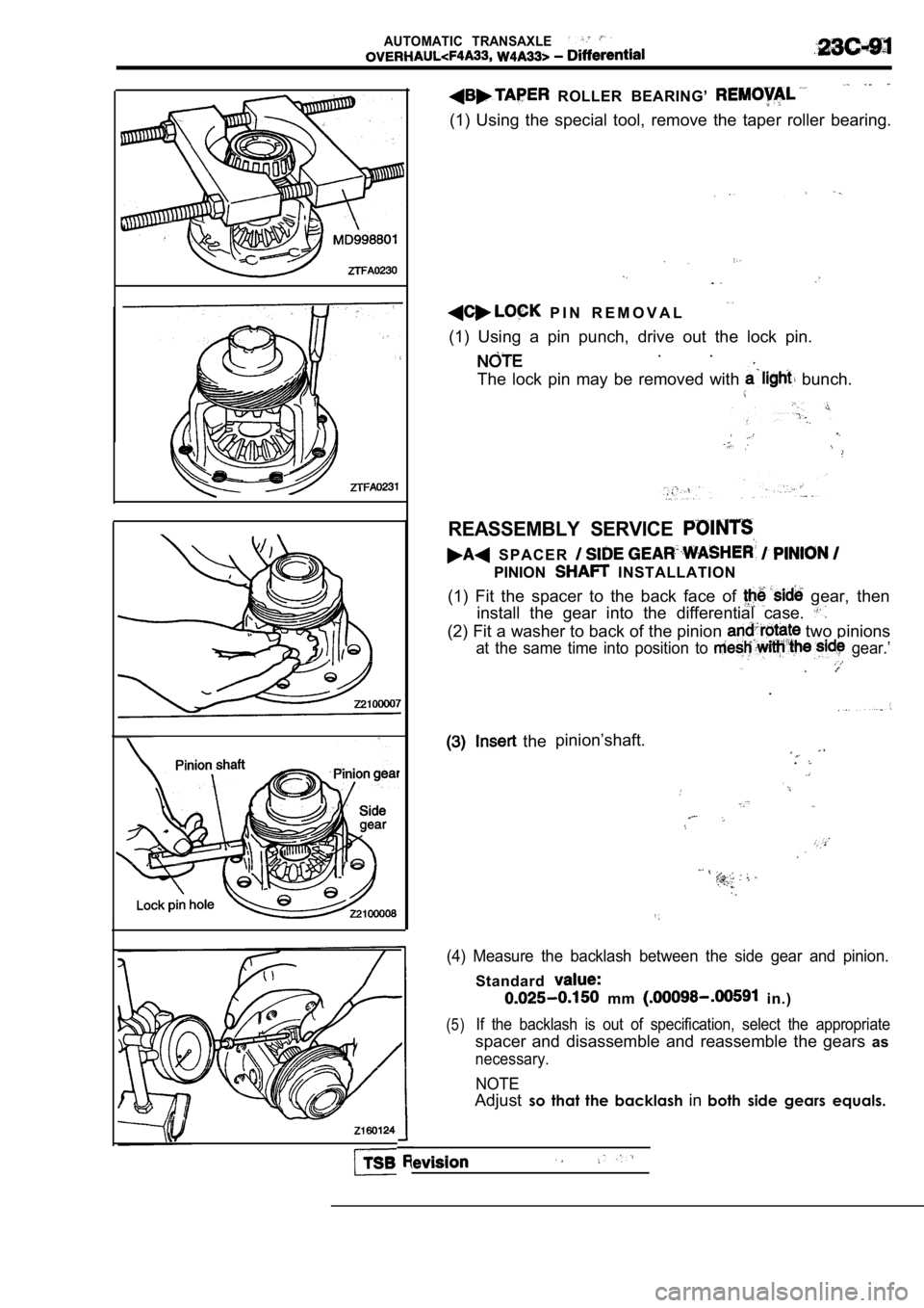
(1) Using the special tool, remove the taper roller bearing.
P I N R E M O V A L
(1) Using a pin punch, drive out the lock pin.. .
The lock pin may be removed with
bunch.
REASSEMBLY SERVICE
S P A C E R
PINION INSTALLATION
(1) Fit the spacer to the back face of
gear, then
install the gear into the differential case.
(2) Fit a washer to back of the pinion two pinions
at the same time into position to gear.’
. . .
.
pinion’shaft.
.
(4) Measure the backlash between the side gear and pinion.
Standard
mm in.)
(5)If the backlash is out of specification, select the appropriate
spacer and disassemble and reassemble the gears as
necessary.
NOTE
Adjustso that the backlash inboth side gears equals.
Page 1376 of 2103
A U T O M A T I C
-Differential
2160030
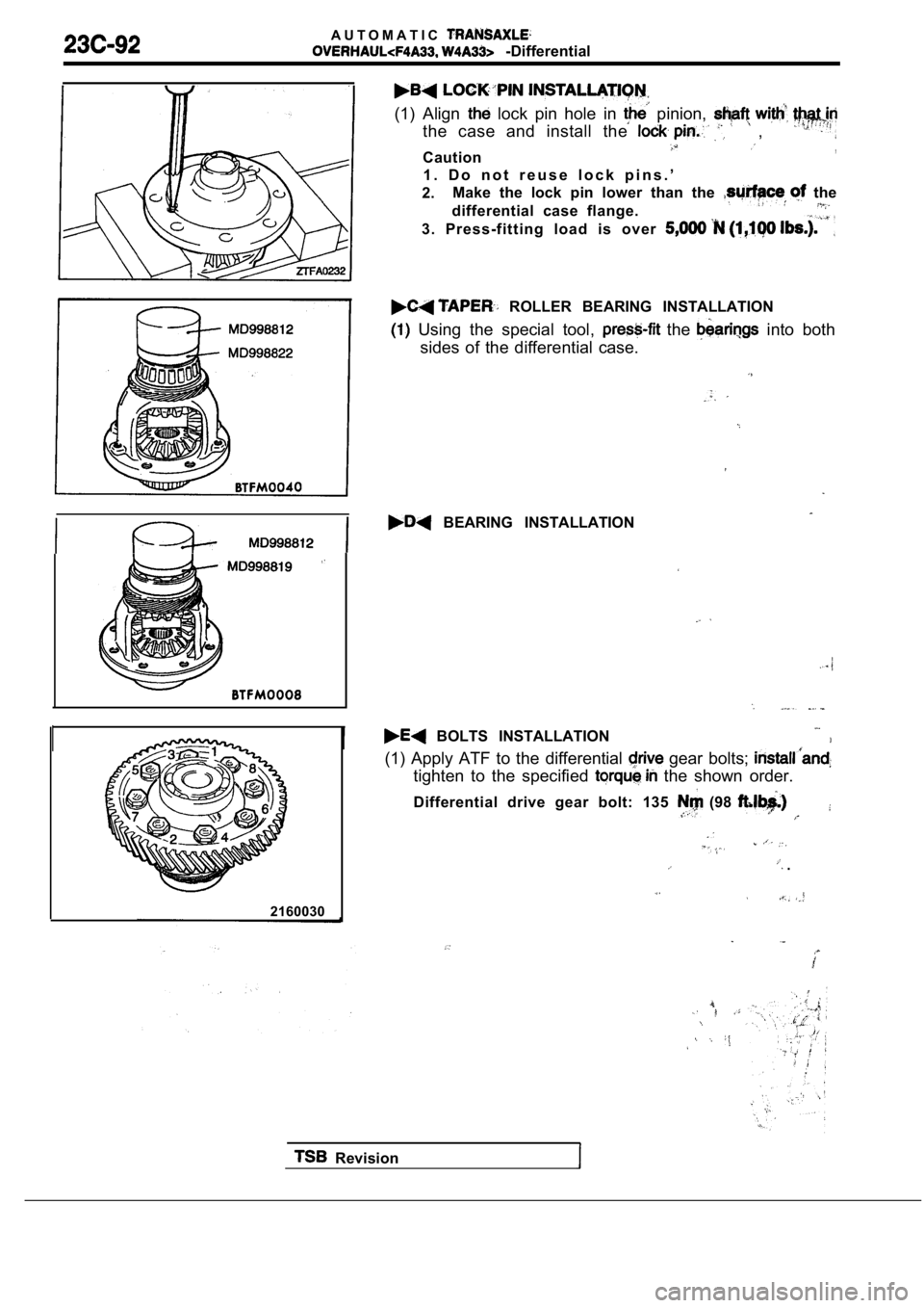
(1) Align lock pin hole in pinion,
the case and install the ,
Caution,
1 . D o n o t r e u s e l o c k p i n s . ’
2. Make the lock pin lower than the
the
differential case flange.
3. Press-fitting load is over
ROLLER BEARING INSTALLATION
Using the special tool, the into both
sides of the differential case.
BEARING INSTALLATION
BOLTS INSTALLATION
(1) Apply ATF to the differential
gear bolts;
tighten to the specified the shown order.
Differential drive gear bolt: 135
(98
.
Revision
Page 1377 of 2103
AUTOMATIC TRANSAXLE
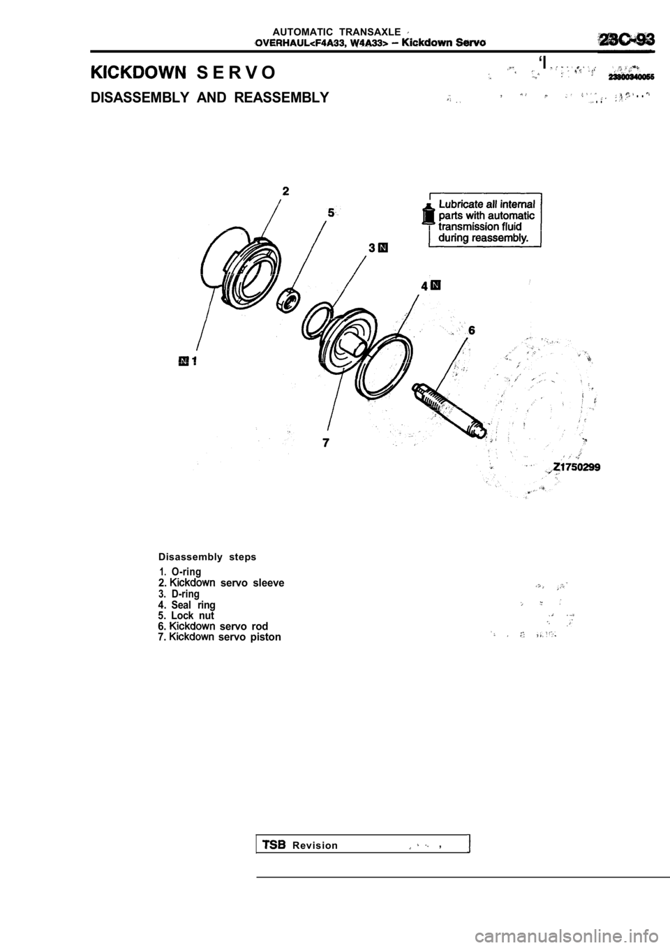
S E R V O‘I
DISASSEMBLY AND REASSEMBLY . . . .
Disassembly steps
1.O-ring2. servo sleeve3. D-ring4. Seal ring
5. Lock nut
6. servo rod
7. servo piston
R e v i s i o n ,
Page 1378 of 2103
AUTOMATIC TRANSAXLE
Low-reverse Brake
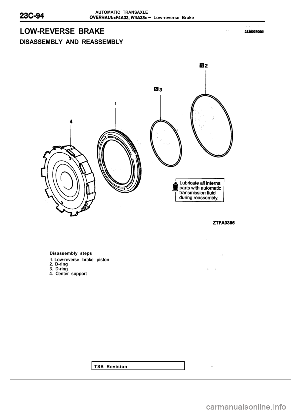
LOW-REVERSE BRAKE
DISASSEMBLY AND REASSEMBLY
1
T S B R e v i s i o n
Disassembly steps
1.Low-reverse brake piston2. D-ring3. D-ring
4. Center support
Page 1379 of 2103
AUTOMATIC TRANSAXLE.
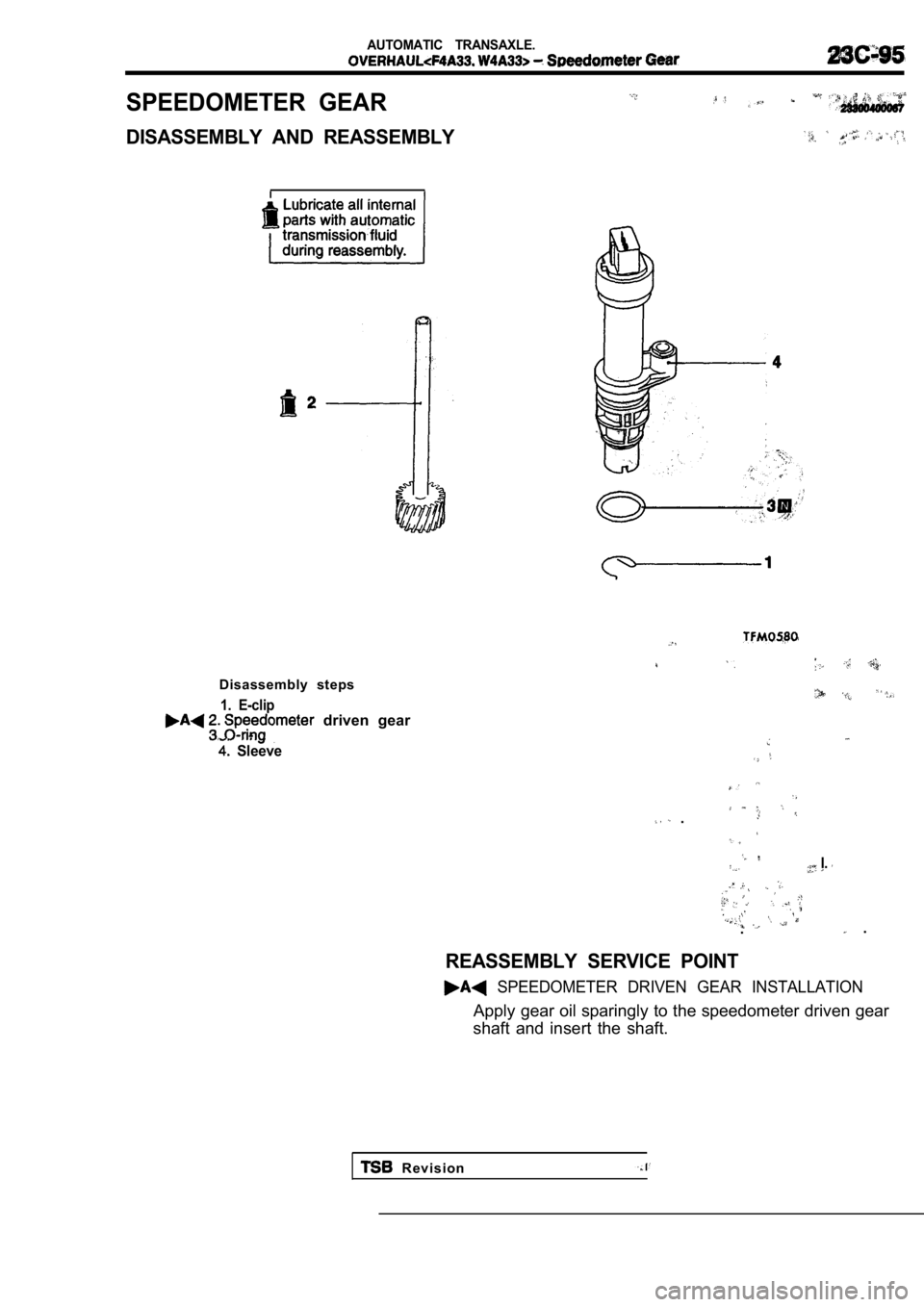
SPEEDOMETER GEAR
DISASSEMBLY AND REASSEMBLY
Disassembly steps
1. E-clip driven gear
Sleeve
.
I.
. .
REASSEMBLY SERVICE POINT
SPEEDOMETER DRIVEN GEAR INSTALLATION
Apply gear oil sparingly to the speedometer driven gear
shaft and insert the shaft.
R e v i s i o n
Page 1380 of 2103
AUTOMATIC TRANSAXLE
-Transfer Shaft
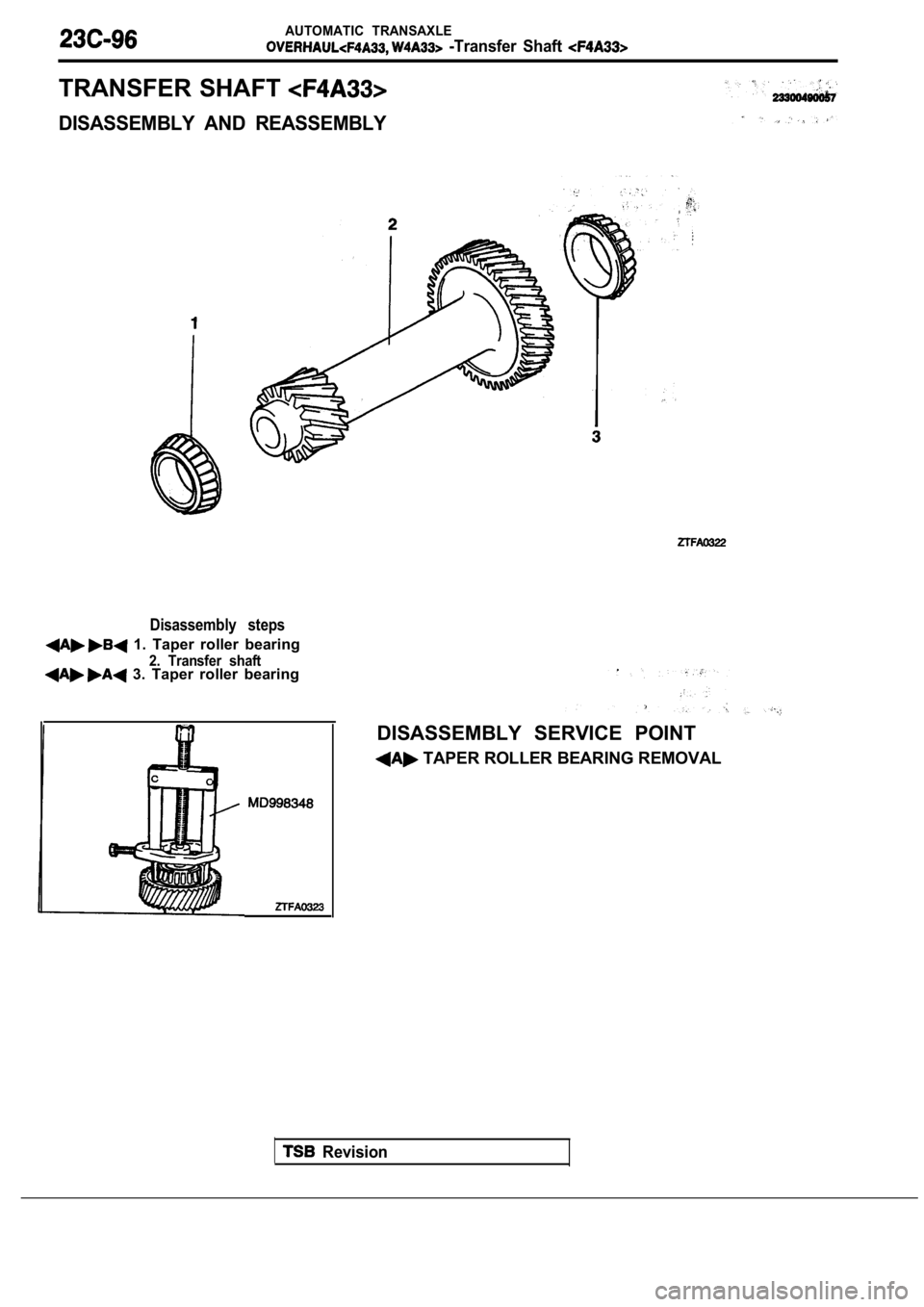
TRANSFER SHAFT
DISASSEMBLY AND REASSEMBLY
Disassembly steps
1. Taper roller bearing
2. Transfer shaft 3. Taper roller bearing
Revision
DISASSEMBLY SERVICE POINT
TAPER ROLLER BEARING REMOVAL
Trending: air condition, inflation pressure, water pump, steering wheel, fuel cap release, bulb, change wheel
