MITSUBISHI SPYDER 1990 Service Repair Manual
SPYDER 1990
MITSUBISHI
MITSUBISHI
https://www.carmanualsonline.info/img/19/57345/w960_57345-0.png
MITSUBISHI SPYDER 1990 Service Repair Manual
Trending: cooling, washer fluid, service schedule, trunk release, fuel consumption, octane, engine oil
Page 1361 of 2103
A U T O M A T I C T R A N S A X L E
11 Nm
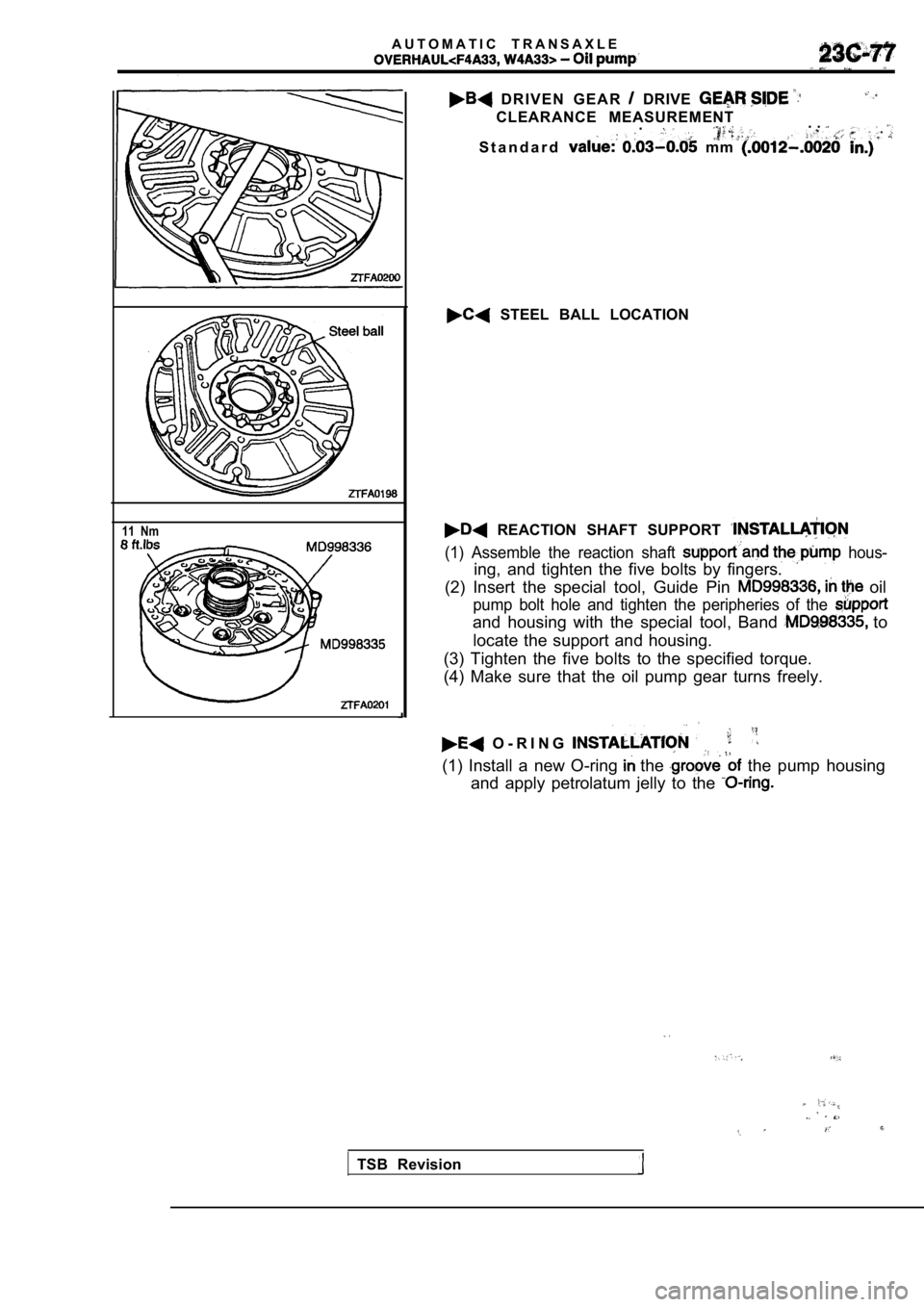
D R I V E N G E A R DRIVE
CLEARANCE MEASUREMENT.. .
S t a n d a r d mm
STEEL BALL LOCATION
REACTION SHAFT SUPPORT
(1) Assemble the reaction shaft hous-
ing, and tighten the five bolts by fingers.
(2) Insert the special tool, Guide Pin
oil
pump bolt hole and tighten the peripheries of the
and housing with the special tool, Band to
locate the support and housing.
(3) Tighten the five bolts to the specified torque.
(4) Make sure that the oil pump gear turns freely.
O - R I N G
(1) Install a new O-ring the the pump housing
and apply petrolatum jelly to the
TSB Revision
Page 1362 of 2103
AUTOMATIC TRANSAXLE Front ,
FRONT CLUTCH
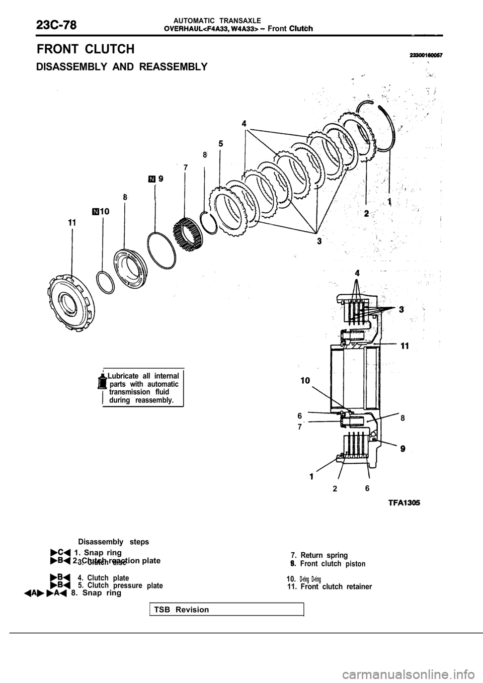
DISASSEMBLY AND REASSEMBLY
8
8
7I
Disassembly steps
1. Snap ring 2. Clutch reaction plate3.Clutchdisc
4. Clutchplate5. Clutchpressureplate 8. Snap ring
7. Return spring
8.Front clutchpiston9.
10.
D-ring D-ring11. Front clutch retainer
TSB Revision
Lubricate all internal
parts with automatictransmission fluid
during reassembly.
6
7
8
2 6
Page 1363 of 2103
A U T O M A T I C “ T R A N S A X L E .
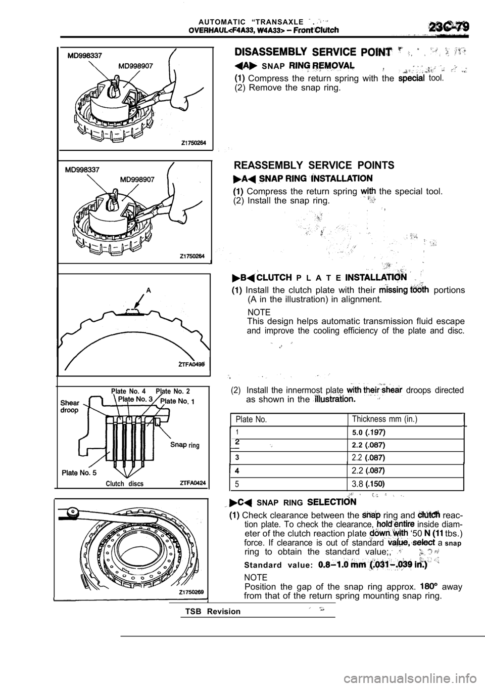
SNAP
Compress the return spring with thetool.
(2) Remove the snap ring.
REASSEMBLY SERVICE POINTS
Compress the return spring the special tool.
(2) Install the snap ring.
,
P L A T E
Install the clutch plate with their portions
(A in the illustration) in alignment.
NOTE
This design helps automatic transmission fluid esca pe
and improve the cooling efficiency of the plate and disc.
Plate No. 4 Plate No. 2
ring
Clutch discs
(2)Install the innermost plate droops directed
as shown in the
Plate No.Thickness mm (in.)
15.0
2.2
32.2
Position the gap of the snap ring approx. away
from that of the return spring mounting snap ring.
TSB Revision
2.2
53.8
SNAP RING
Check clearance between the ring and reac-
tion plate. To check the clearance, inside diam-
eter of the clutch reaction plate ‘50 tbs.)
force. If clearance is out of standard a snap
ring to obtain the standard value;,
S t a n d a r d v a l u e :
NOTE
Page 1364 of 2103
AUTOMATIC TRANSAXLE
Rear
. . . . .
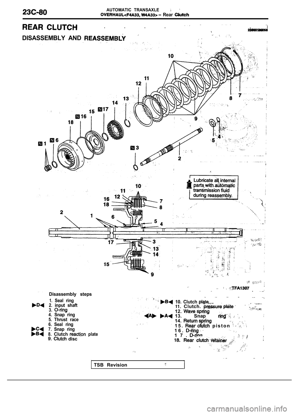
DISASSEMBLY AND
Disassembly steps
1.Seal ring2.input shaft3.
4.
5.Snap ring
Thrust race
6.
7.Seal ring
8.
Snap ring
Clutch discplate
.
10. Clutch Clutch.
12.13. Snap 14.
1 5 . p i s t o n 1 6 .1 7 .
TSB Revision
Page 1365 of 2103
A U T O M A T I C
Rear
,
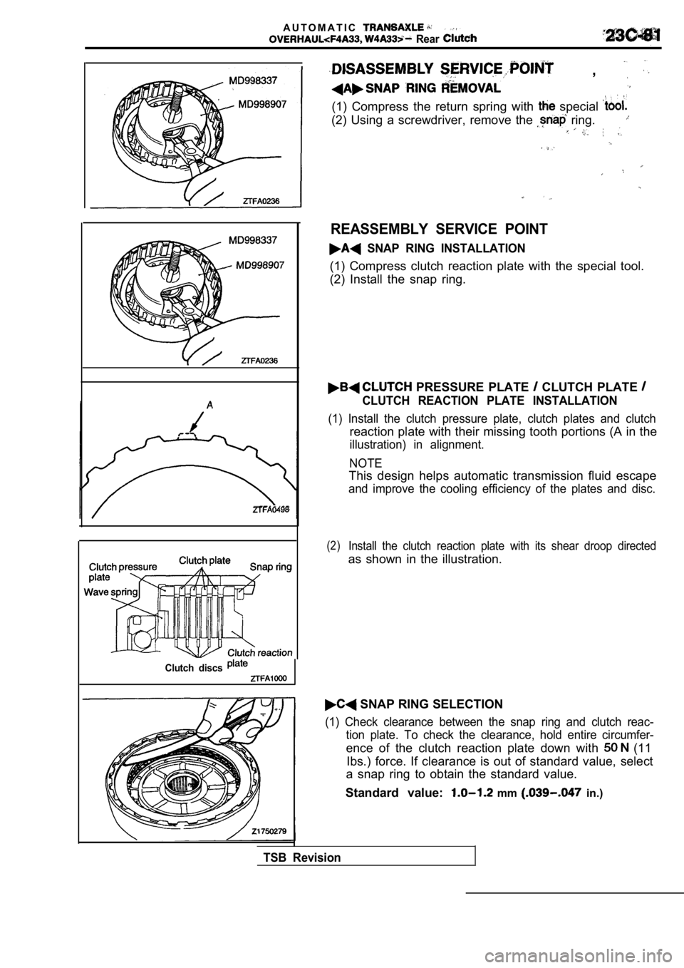
(1) Compress the return spring with special
(2) Using a screwdriver, remove the ring.
Clutch discs
REASSEMBLY SERVICE POINT
SNAP RING INSTALLATION
(1) Compress clutch reaction plate with the special tool.
(2) Install the snap ring.
PRESSURE PLATE CLUTCH PLATE
CLUTCH REACTION PLATE INSTALLATION
(1) Install the clutch pressure plate, clutch plate s and clutch
reaction plate with their missing tooth portions (A in the
illustration) in alignment.
NOTE
This design helps automatic transmission fluid esca pe
and improve the cooling efficiency of the plates and disc.
(2)Install the clutch reaction plate with its shear droop directed
as shown in the illustration.
SNAP RING SELECTION
(1) Check clearance between the snap ring and clutc h reac-
tion plate. To check the clearance, hold entire cir cumfer-
ence of the clutch reaction plate down with (11
Ibs.) force. If clearance is out of standard value, select
a snap ring to obtain the standard value.
Standard value:
mm in.)
TSB Revision
Page 1366 of 2103
AUTOMATIC TRANSAXLE
Rear
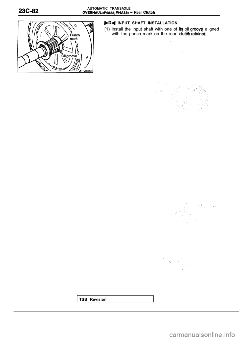
INPUT SHAFT INSTALLATION
(1) Install the input shaft with one of
oil aligned
with the punch mark on the rear’
TSB Revision
Page 1367 of 2103
A U T O M A T I C T R A N S A X L E
End Clutch
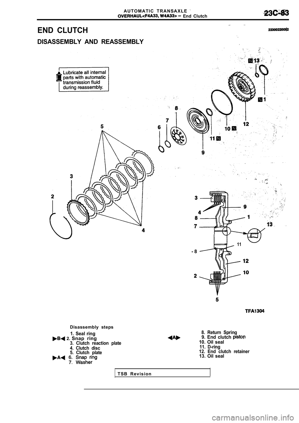
END CLUTCH
DISASSEMBLY AND REASSEMBLY
11
- 8
Disassembly steps
1. Seal ring 2. Snap ring3. Clutch reaction plate
4. Clutch disc
5. Clutch plate
8. Return Spring9. End clutch 10. Oil seal11. D-ring
12. End clutch retainer
13. Oil seal
T S B R e v i s i o n
Page 1368 of 2103
AUTOMATIC TRANSAXLE
End
T S B R e v i s i o n
T S B R e v i s i o n DISASSEMBLY SERVICE
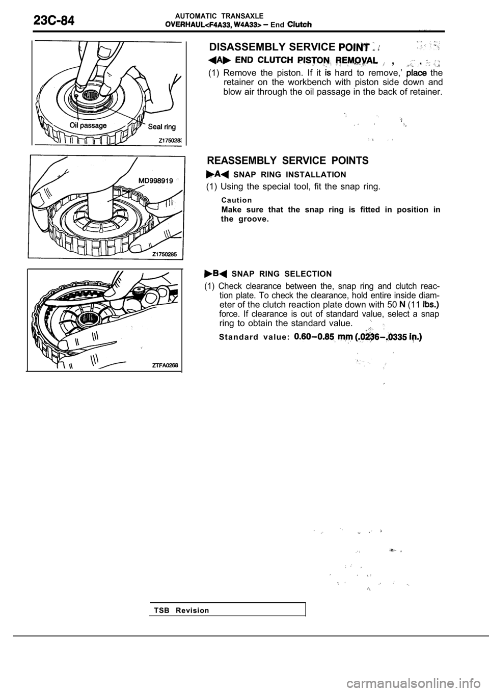
, ,
(1) Remove the piston. If it hard to remove,’ the
retainer on the workbench with piston side down and
blow air through the oil passage in the back of ret ainer.
REASSEMBLY SERVICE POINTS
SNAP RING INSTALLATION
(1) Using the special tool, fit the snap ring.
C a u t i o n
Make sure that the snap ring is fitted in position in
the groove.
SNAP RING SELECTION
(1) Check clearance between the, snap ring and clut ch reac-
tion plate. To check the clearance, hold entire ins ide diam-
eter of the clutch reaction plate down with 50 (11
force. If clearance is out of standard value, selec t a snap
ring to obtain the standard value.
S t a n d a r d v a l u e :
Page 1369 of 2103
AUTOMATIC
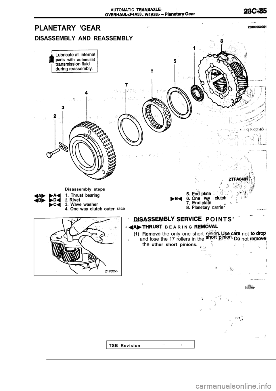
PLANETARY ‘GEAR
DISASSEMBLY AND REASSEMBLY
parts with automatic
6
I
Disassembly steps
1. Thrust bearing
2.Rivet
3. Wave washer
4. One way clutch outer
race
. .
End
Planetarycarrier
P O I N T S ’
B E A R I N G
(1) the only one short not
and lose the 17 rollers in the not
the other short pinions.
.
T S B R e v i s i o n
Page 1370 of 2103
AUTOMATIC TRANSAXLE
Planetary Gear
RIVET REMOVAL
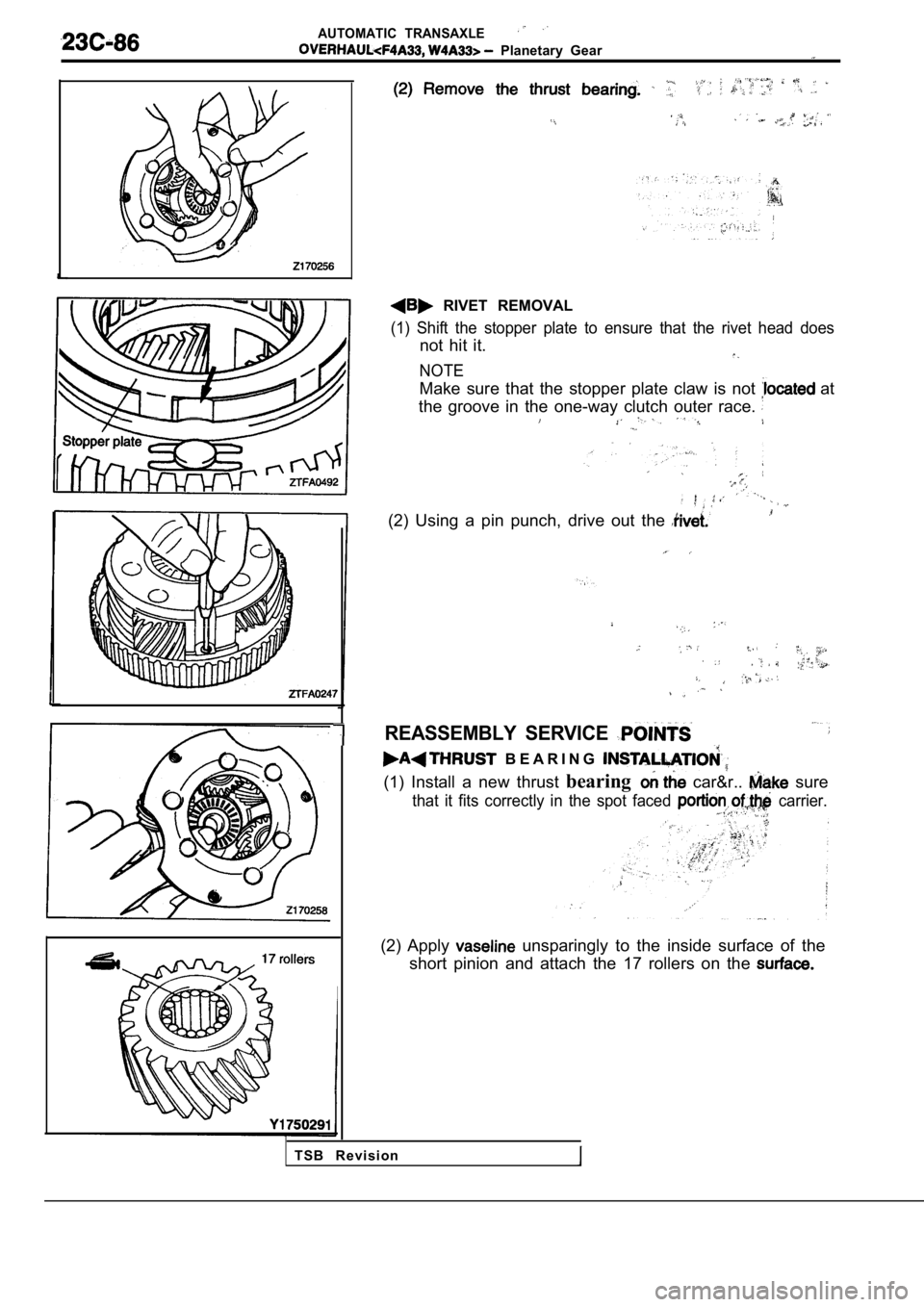
(1) Shift the stopper plate to ensure that the rivet head does
not hit it.
NOTE
Make sure that the stopper plate claw is not at
the groove in the one-way clutch outer race.
(2) Using a pin punch, drive out the
REASSEMBLY SERVICE
B E A R I N G
(1) Install a new thrust bearing car&r.. sure
that it fits correctly in the spot faced carrier..
(2) Apply unsparingly to the inside surface of the
short pinion and attach the 17 rollers on the
T S B R e v i s i o n
Trending: check engine, fuel pump, trailer, radiator, gas type, spark plugs, torque
