MITSUBISHI SPYDER 1990 Service Repair Manual
SPYDER 1990
MITSUBISHI
MITSUBISHI
https://www.carmanualsonline.info/img/19/57345/w960_57345-0.png
MITSUBISHI SPYDER 1990 Service Repair Manual
Trending: display, seats, horn, wheel torque, engine overheat, timing belt, steering wheel adjustment
Page 1391 of 2103
AUTOMATIC TRANSAXLE
-Transfer
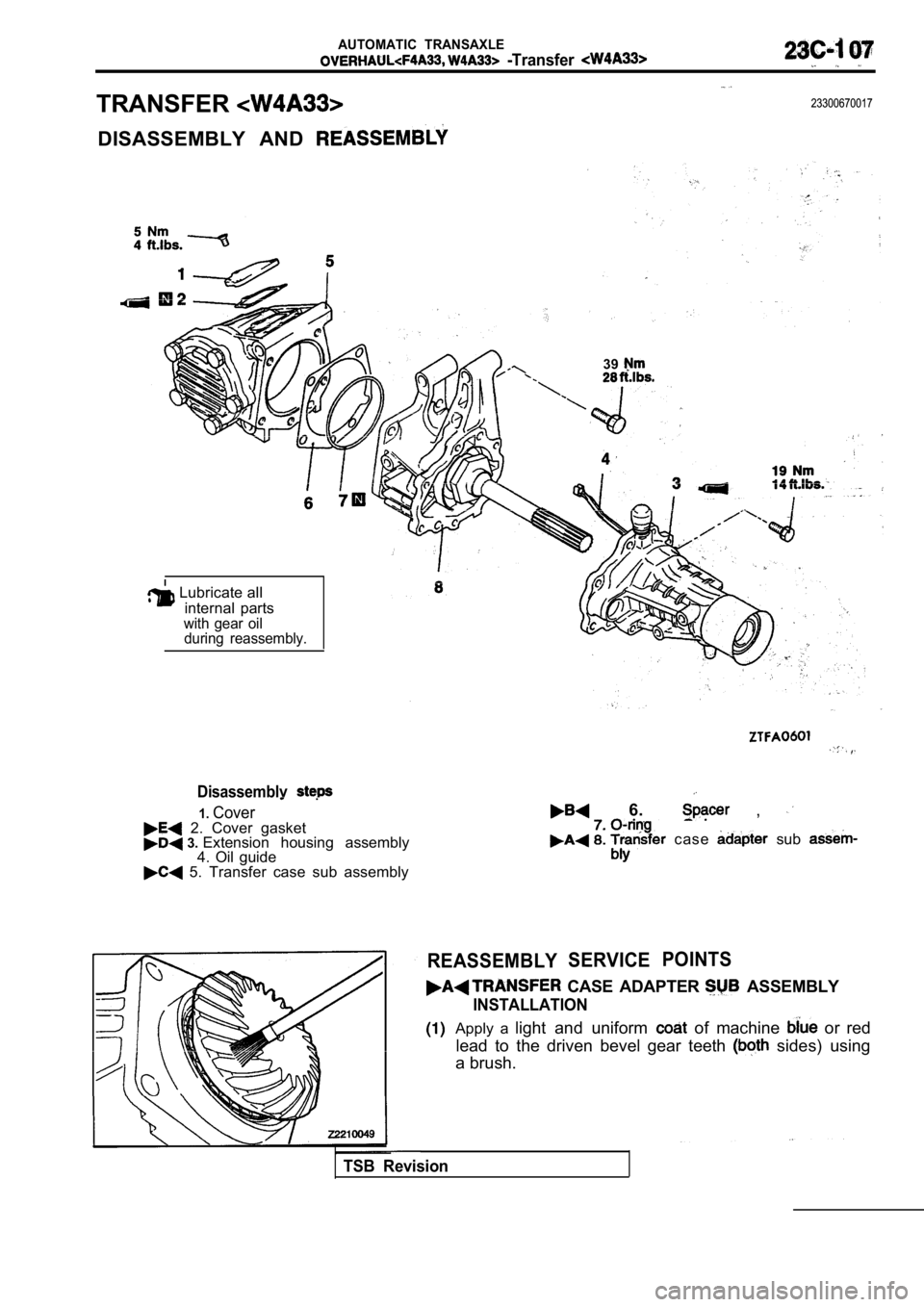
TRANSFER23300670017
DISASSEMBLY AND
39
Lubricate all internal parts
with gear oilduring reassembly.
Disassemblv .
1.Cover 2. Cover gasket 3. Extension housing assembly
4. Oil guide
5. Transfer case sub assembly
6. ,
c a s e sub
REASSEMBLYSERVICE POINTS
CASE ADAPTER ASSEMBLY
INSTALLATION
Apply a
light and uniform of machine or red
lead to the driven bevel gear teeth
sides) using
a brush.
TSB Revision
Page 1392 of 2103
AUTOMATIC TRANSAXLE
Transfer .
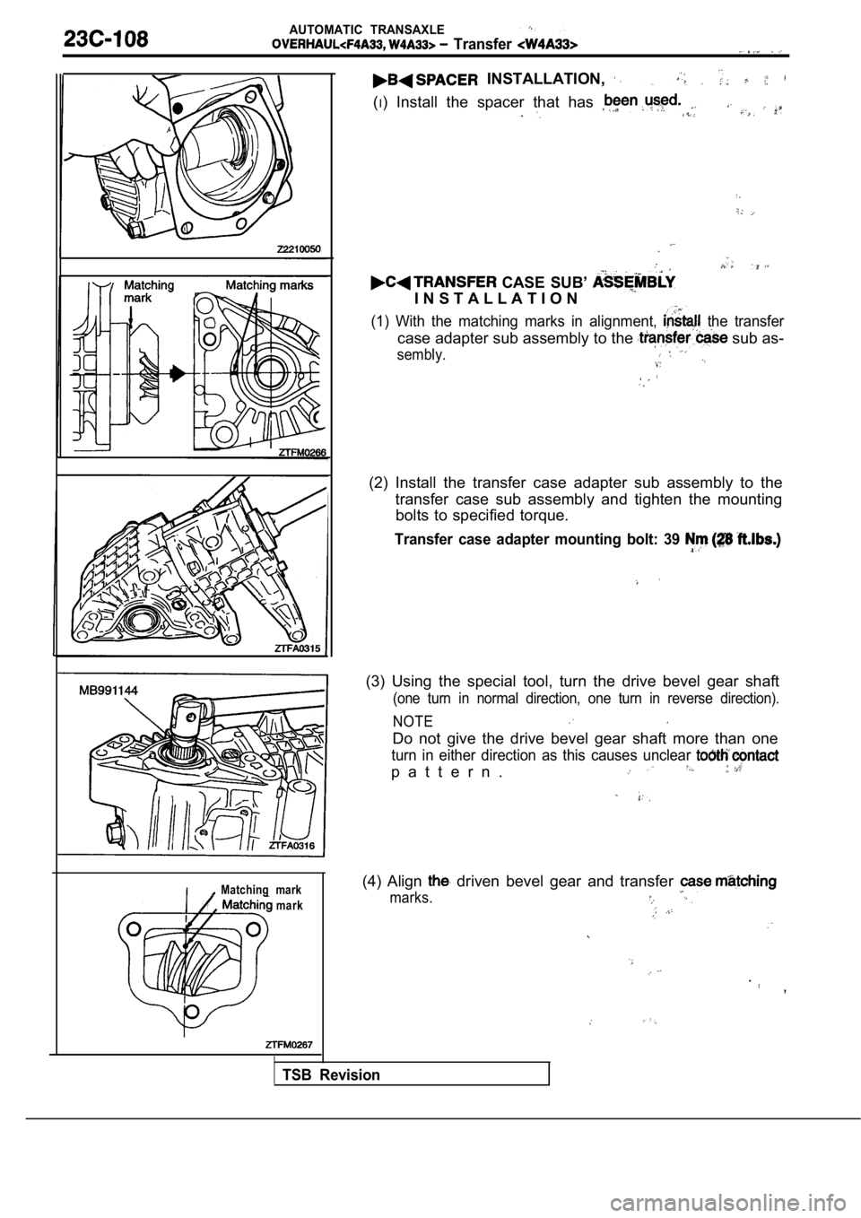
INSTALLATION,
(I) Install the spacer that has
CASE SUB’
I N S T A L L A T I O N
(1) With the matching marks in alignment, the transfer
case adapter sub assembly to the sub as-
sembly.
(2) Install the transfer case adapter sub assembly to the
transfer case sub assembly and tighten the mounting bolts to specified torque.
Transfer case adapter mounting bolt: 39
(3) Using the special tool, turn the drive bevel ge ar shaft
(one turn in normal direction, one turn in reverse direction).
NOTE
Do not give the drive bevel gear shaft more than on e
turn in either direction as this causes unclear
p a t t e r n .
Matching mark
mark(4) Align driven bevel gear and transfer
marks.
. ,
TSB Revision
Page 1393 of 2103
00
0
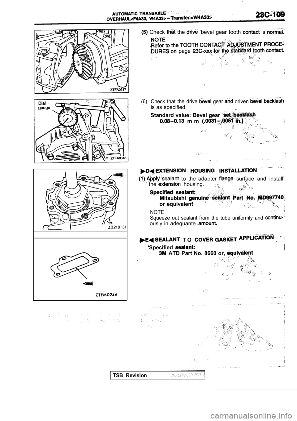
Check the ‘bevel gear tooth is
page
..
(6)Check that the drive gear driven
is as specified. .
Standard value: Bevel gear
m m
--
to the adapter surface and install’
the housing.
Mitsubishi
or equivalent ,
NOTE
Squeeze out sealant from the tube uniformly and
ously in adequante
T O .
‘Specified
ATD Part No. 8660 or,
TSB Revision
Page 1394 of 2103
A U T O M A T I C T R A N S A X L E
Transfer
I
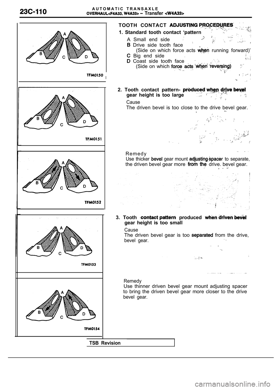
TOOTH CONTACT
1. Standard tooth contact ‘pattern
A Small end side
Drive side tooth face,
(Side on which force acts
running forward)’
Big end side
Coast side tooth face
(Side on which
,
2. Tooth contact pattern-
gear height is too large
Cause
The driven bevel is too close to the drive bevel ge ar.
R e m e d y
Use thicker gear mount to separate,
the driven bevel gear more drive. bevel gear., .
3. Tooth produced
gear height is too small
Cause
The driven bevel gear is too from the drive,
bevel gear.. ..
Remedy
Use thinner driven bevel gear mount adjusting space r
to bring the driven bevel gear more closer to the d rive
bevel gear.
TSB Revision
Page 1395 of 2103
AUTOMATIC TRANSAXLE
Transfer
Drive bevel gearmount adjusting
spacer
.
Drive bevel gearpreload adjusting spacer
Driven beve
Driven beve
gear preloac
adjustingspacer
.
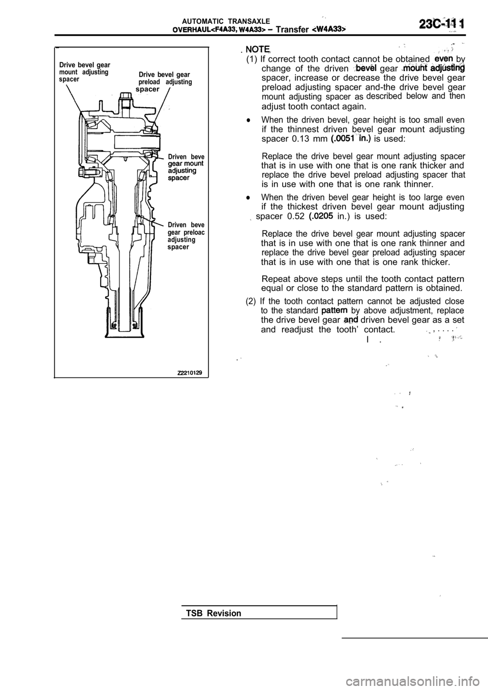
(1) If correct tooth contact cannot be obtained by
change of the driven
gear
spacer, increase or decrease the drive bevel gear preload adjusting spacer and-the drive bevel gear
mount adjusting spacer as described
below and then
adjust tooth contact again.
lWhen the driven bevel, gear height is too small eve
n
if the thinnest driven bevel gear mount adjusting
spacer 0.13 mm
is used:
Replace the drive bevel gear mount adjusting spacer
that is in use with one that is one rank thicker an d
replace the drive bevel preload adjusting spacer th at
is in use with one that is one rank thinner.
lWhen the driven bevel gear height is too large even
if the thickest driven bevel gear mount adjusting
spacer 0.52 in.) is used:
Replace the drive bevel gear mount adjusting spacer
that is in use with one that is one rank thinner and
replace the drive bevel gear preload adjusting spac er
that is in use with one that is one rank thicker.
Repeat above steps until the tooth contact pattern
equal or close to the standard pattern is obtained.
(2) If the tooth contact pattern cannot be adjusted close
to the standard
by above adjustment, replace
the drive bevel gear driven bevel gear as a set
and readjust the tooth’ contact.
, . . . .
I .
.
TSB Revision
Page 1396 of 2103
AUTOMATIC TRANSAXLE
-Transfer
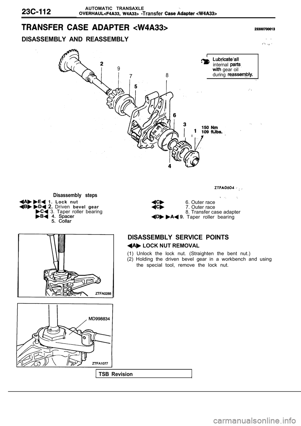
DISASSEMBLY AND REASSEMBLY
9
78
. .
internal gear oil
during
Disassembly steps
1 . L o c k n u t 2. Driven b e v e l g e a r 3. Taper roller bearing
,
,
6. Outer race7. Outer race
8. Transfer case adapter
Taper roller bearing
DISASSEMBLY SERVICE POINTS
LOCK NUT REMOVAL
(1) Unlock the lock nut. (Straighten the bent nut.)
(2) Holding the driven bevel gear in a workbench an d using
the special tool, remove the lock nut.
TSB Revision
Page 1397 of 2103
AUTOMATIC TRANSAXLE
-Transfer Case Adapter
2
4
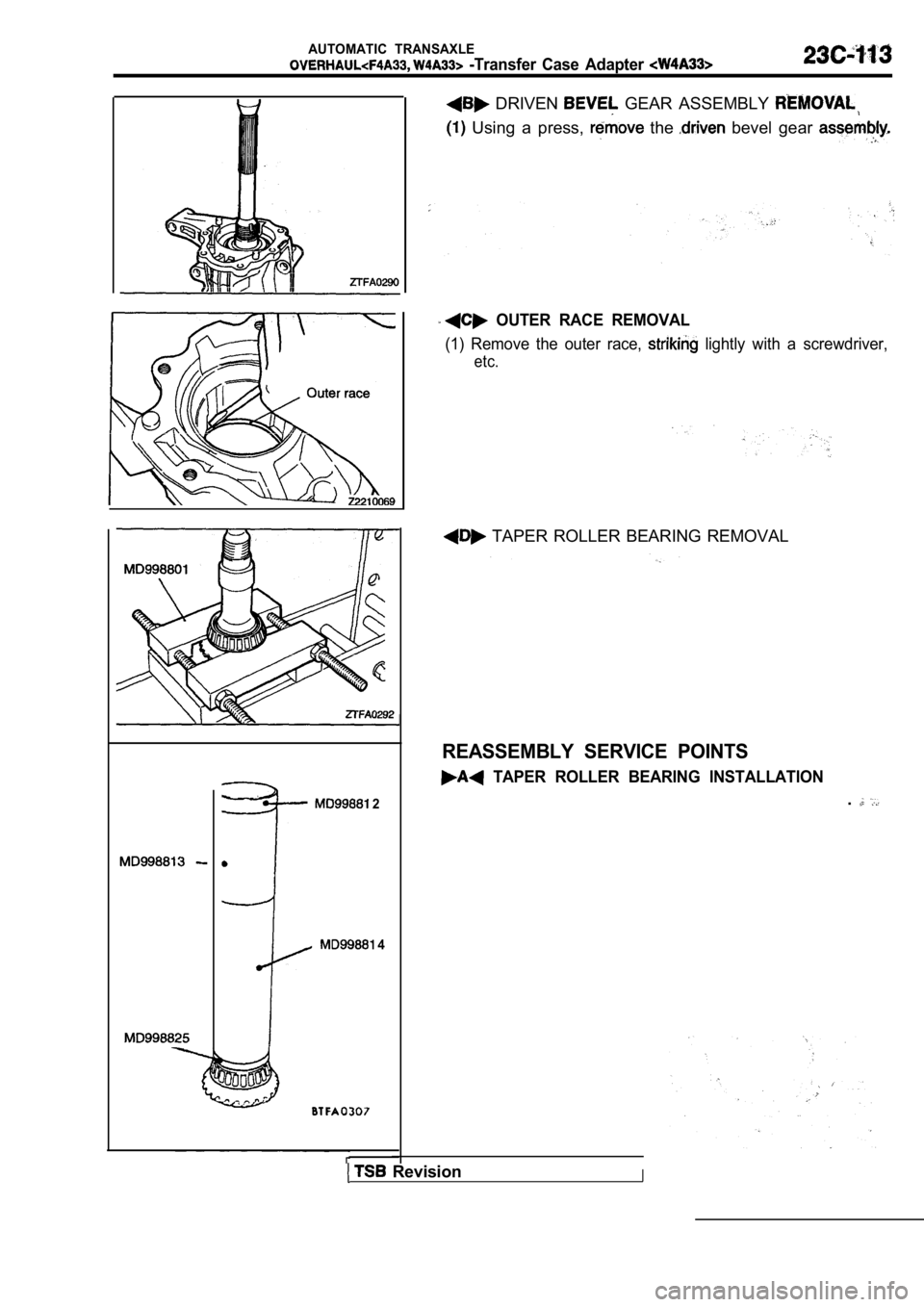
DRIVEN GEAR ASSEMBLY
Using a press, the bevel gear
OUTER RACE REMOVAL
(1) Remove the outer race, lightly with a screwdriver,
etc.
TAPER ROLLER BEARING REMOVAL
REASSEMBLY SERVICE POINTS
TAPER ROLLER BEARING INSTALLATION
.
RevisionI
Page 1398 of 2103
AUTOMATIC TRANSAXLE
Transfer Case Adapter
2
Matching mark
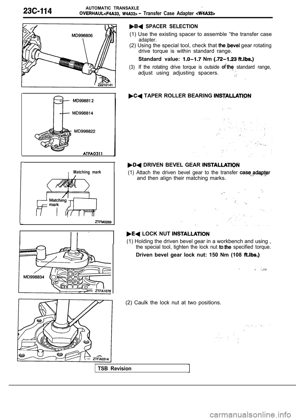
SPACER SELECTION
(1) Use the existing spacer to assemble “the transfer case
adapter.
(2) Using the special tool, check that gear rotating
drive torque is within standard range.
Standard value:
Nm
(3)If the rotating drive torque is outside standard range,
adjust using adjusting spacers.
TAPER ROLLER BEARING
DRIVEN BEVEL GEAR
(1) Attach the driven bevel gear to the transfer
and then align their matching marks.
. .
LOCK NUT
(1) Holding the driven bevel gear in a workbench an d using ,
the special tool, tighten the lock nut specified torque.
Driven bevel gear lock nut: 150 Nm (108
(2) Caulk the lock nut at two positions.
TSB Revision
Page 1399 of 2103
A U T O M A T I C T R A N S A X L E.
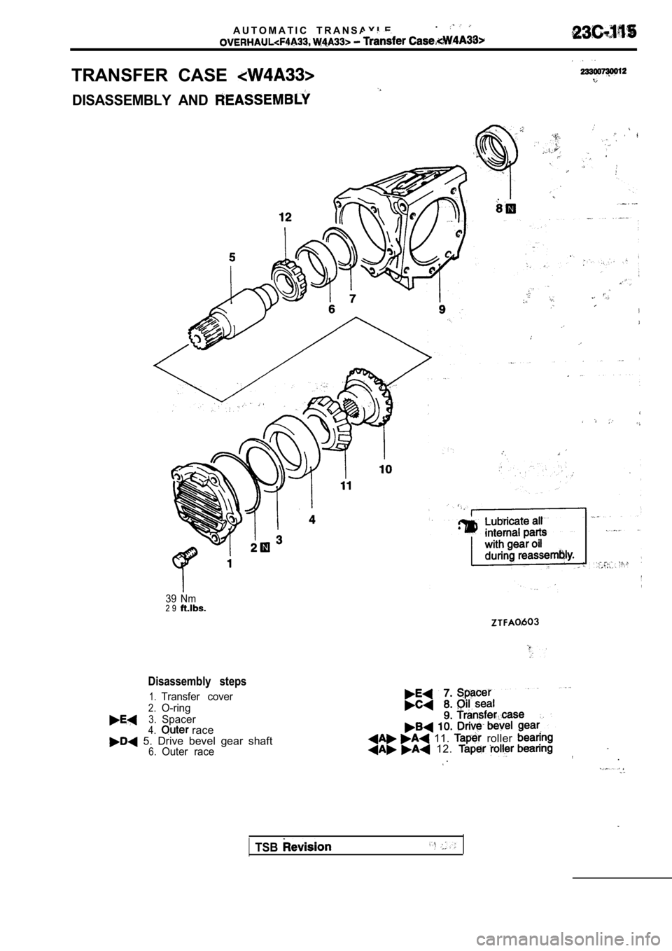
TRANSFER CASE
DISASSEMBLY AND
39 Nm2 9
Disassembly steps
1.Transfer cover
2.O-ring
3.Spacer4. race 5. Drive bevel gear shaft6.Outer race
11. roller 12. .
.
TSB
Page 1400 of 2103
AUTOMATIC TRANSAXLE
Case
1II I
8
REASSEMBLY SERVICE
ROLLER BEARING INSTALLATION
DRIVE BEVEL GEAR
(1) Install the drive bevel gear to the shaft
with their matching marks in
TSB Revision
Trending: clutch, turn signal, power steering, check engine, clock, brake pads replacement, warning
