MITSUBISHI SPYDER 1990 Service Repair Manual
SPYDER 1990
MITSUBISHI
MITSUBISHI
https://www.carmanualsonline.info/img/19/57345/w960_57345-0.png
MITSUBISHI SPYDER 1990 Service Repair Manual
Trending: boot, fuel tank removal, change wheel, parking sensors, weight, manual transmission, heater
Page 1381 of 2103
A U T O M A T I C T R A N S A X L E
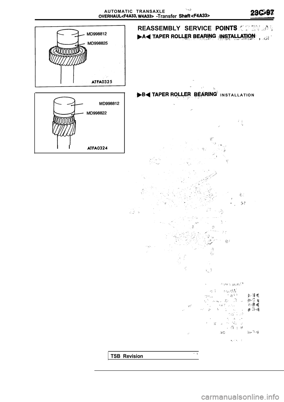
-Transfer
REASSEMBLY SERVICE
,
. . . .
I I
I N S T A L L A T I O N
TSB Revision
Page 1382 of 2103
AUTOMATIC TRANSAXLE
Valve Body
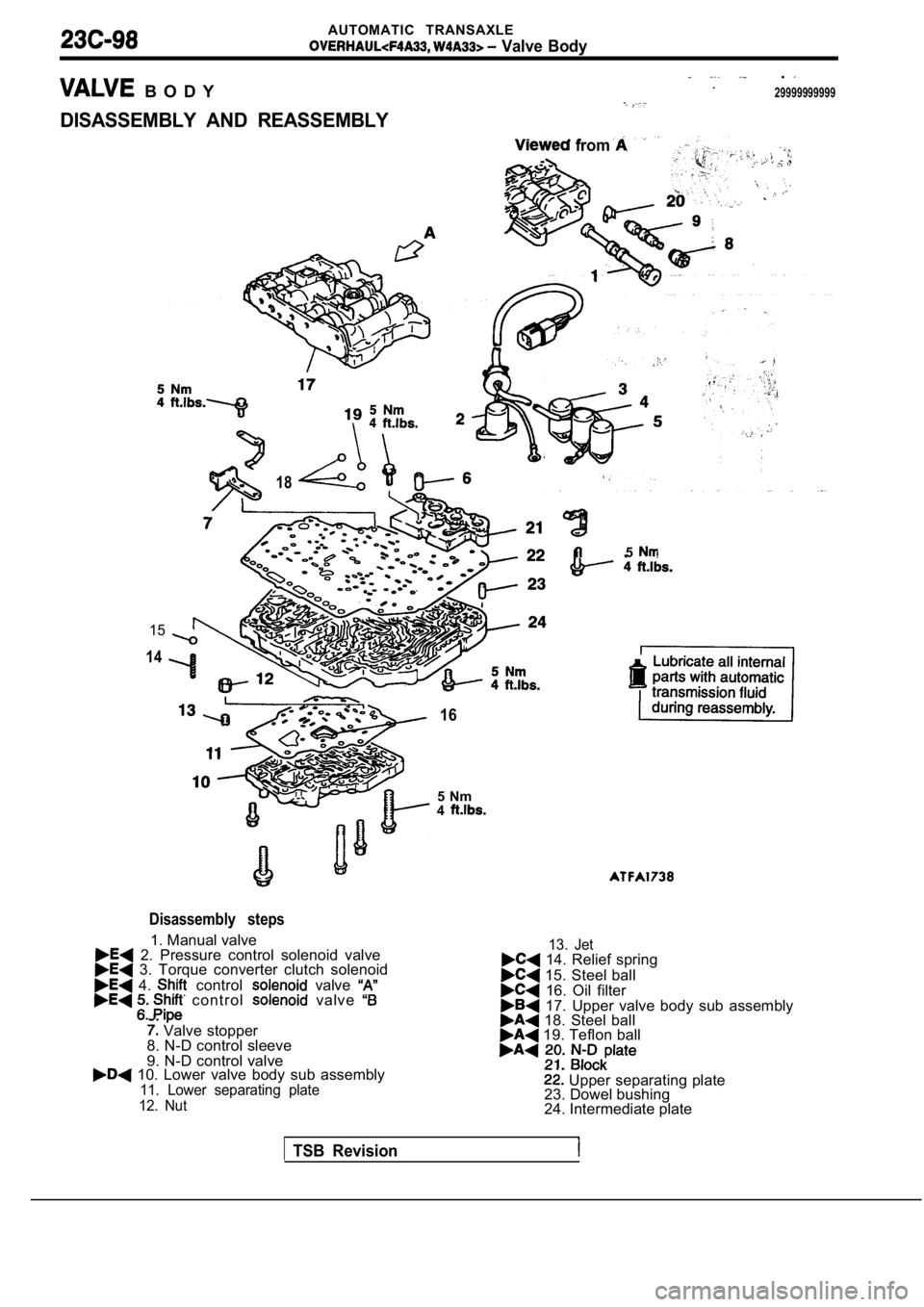
B O D Y
.
29999999999
DISASSEMBLY AND REASSEMBLY
15
14
from
18
Disassembly steps
1. Manual valve 2. Pressure control solenoid valve 3. Torque converter clutch solenoid
4. control valve c o n t r o l valve
Valve stopper
8. N-D control sleeve
9. N-D control valve
10. Lower valve body sub assembly11. Lower separating plate
12. Nut
16
5
5 Nm
4
13. Jet 14. Relief spring
15. Steel ball 16. Oil filter 17. Upper valve body sub assembly 18. Steel ball 19. Teflon ball
Upper separating plate
23. Dowel bushing
24. Intermediate plate
TSB Revision
Page 1383 of 2103
AUTOMATIC TRANSAXLE
47
I5 Nm4
Viewed from
Lubricate all internal
parts with automatic
transmission fluid during reassembly.
5Nm4
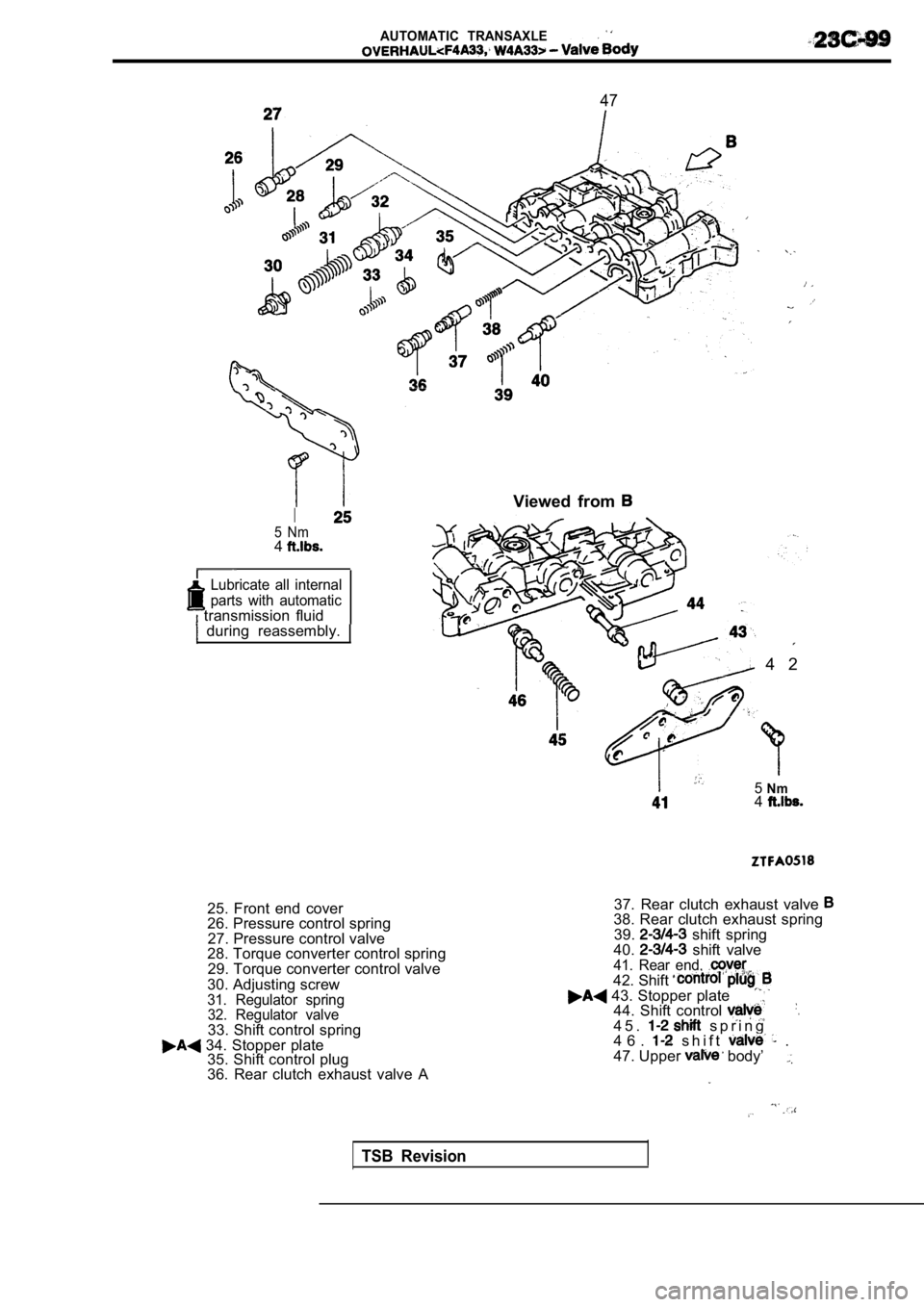
25. Front end cover
26. Pressure control spring27. Pressure control valve
28. Torque converter control spring
29. Torque converter control valve
30. Adjusting screw
31. Regulator spring 32. Regulator valve
33. Shift control spring 34. Stopper plate 35. Shift control plug
36. Rear clutch exhaust valve A 37. Rear clutch exhaust valve
38. Rear clutch exhaust spring
39. shift spring
40. shift valve41. Rear end, 42. Shift 43. Stopper plate44. Shift control .
4 5 . s p r i n g
4 6 . s h i f t .
47. Upper body’
TSB Revision
4 2
Page 1384 of 2103
AUTOMATIC TRANSAXLE
Body
62
69
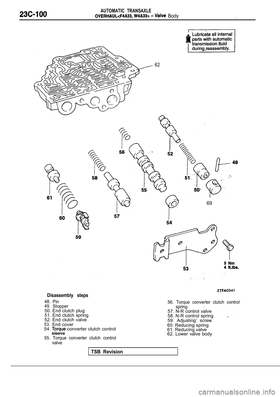
Disassembly steps
48.Pin49.Stopper50. End clutch plug
51. End clutch spring
52. End clutch valve
53.End cover
54. converter clutch control
55. Torque converter clutch control
56. Torque converter clutch control
spring
57. N-R control valve
58. N-R control spring
59. Adjusting’ screw
60. Reducing spring
61. Reducing valve
62. Lower valve body
valve
TSB Revision
Page 1385 of 2103
AUTOMATIC TRANSAXLE
I
I
‘Id
0
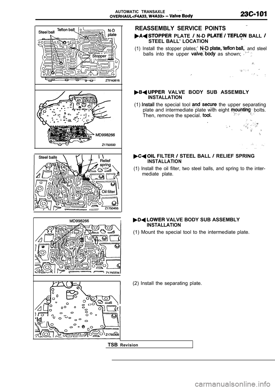
REASSEMBLY SERVICE POINTS
PLATE N-D BALL
STEEL BALL’ LOCATION
(1) Install the stopper plates;’ and steel
balls into the upper as shown;
VALVE BODY SUB ASSEMBLY
INSTALLATION
(1) the special tool the upper separating
plate and intermediate plate with eight
bolts.
Then, remove the special.
.
FILTER STEEL BALL RELIEF SPRING
INSTALLATION
(1) Install the oil filter, two steel balls, and sp ring to the inter-
mediate plate.
VALVE BODY SUB ASSEMBLY
INSTALLATION
(1) Mount the special tool to the intermediate plat e.
(2) Install the separating plate.
TSB Revision
Page 1386 of 2103
AUTOMATIC TRANSAXLE
Valve Body
solenoid
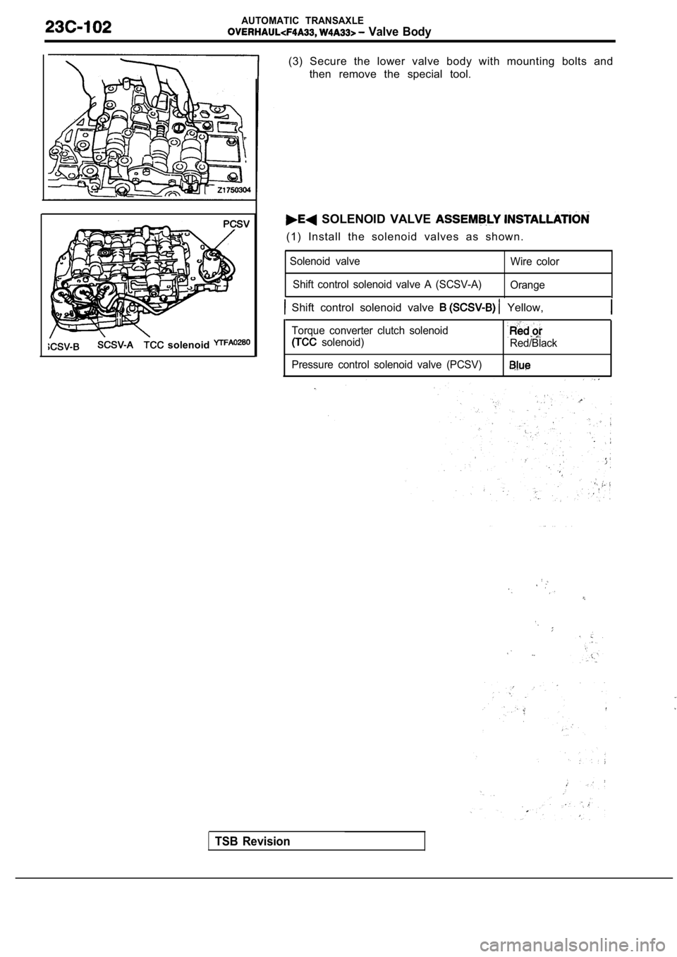
(3) Secure the lower valve body with mounting bolts and
then remove the special tool.
SOLENOID VALVE
(1) Install the solenoid valves as shown.
Solenoid valve
Shift control solenoid valve A (SCSV-A) Wire color
Orange
Shift control solenoid valve Yellow,
Torque converter clutch solenoid
solenoid)Red/Black
Pressure control solenoid valve (PCSV)
TSB Revision
Page 1387 of 2103
AUTOMATIC TRANSAXLE
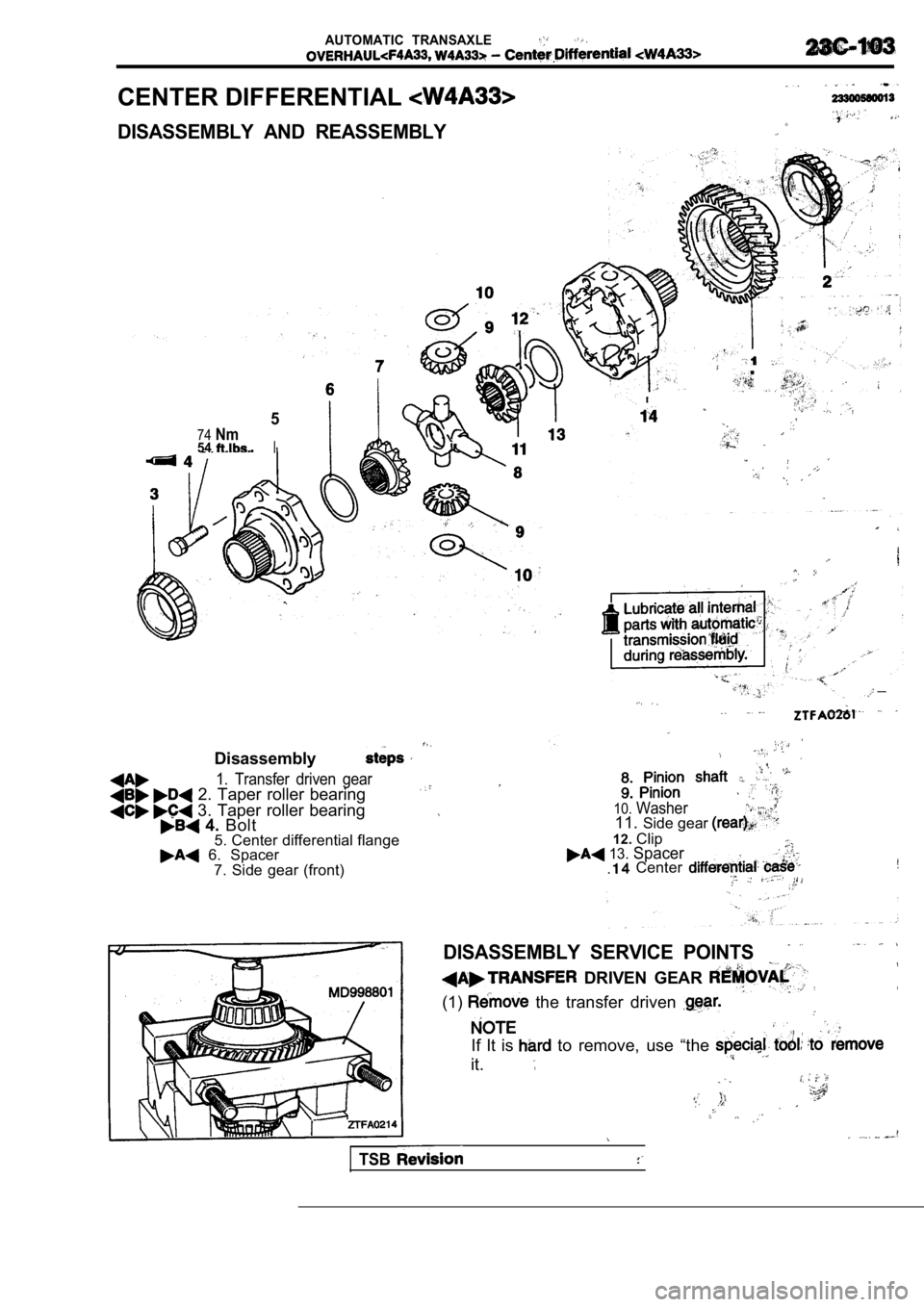
CENTER DIFFERENTIAL ,
DISASSEMBLY AND REASSEMBLY. . .
5
74Nm54I
Disassembly
1. Transfer driven gear 2. Taper roller bearing
3. Taper roller bearing 4. Bolt
5. Center differential flange
6. Spacer
7. Side gear (front)
_ _
10.Washer11. Side gear
12.Clip 13. Spacer Center .
DISASSEMBLY SERVICE POINTS
DRIVEN GEAR
(1) the transfer driven
If It is to remove, use “the
it.
TSB
Page 1388 of 2103
AUTOMATIC TRANSAXLE
. .
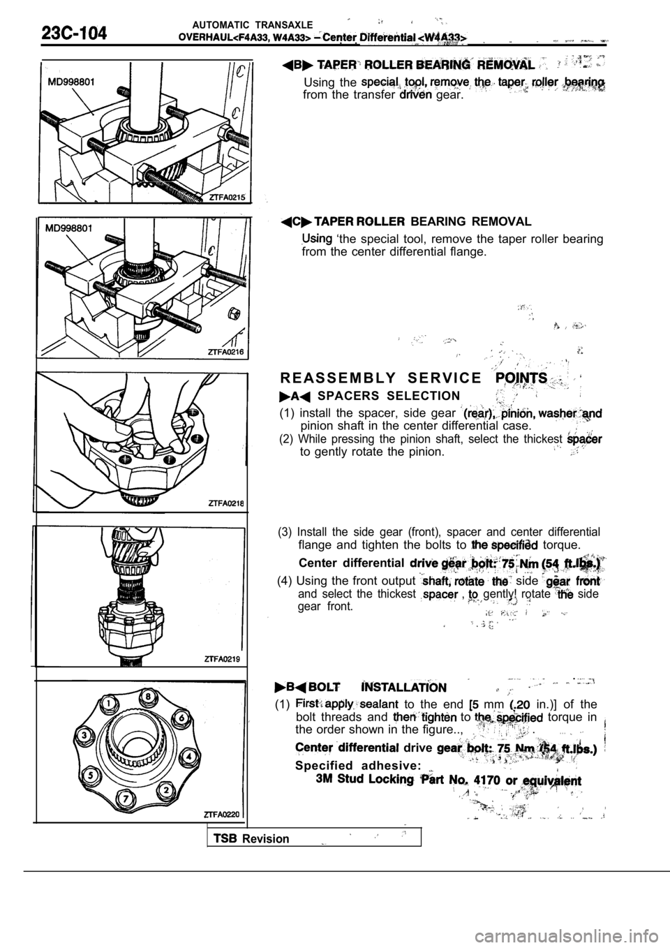
Using the
from the transfer gear.
BEARING REMOVAL
‘the special tool, remove the taper roller bearing
from the center differential flange.
R E A S S E M B L Y S E R V I C E
SPACERS SELECTION
(1) install the spacer, side gear
pinion shaft in the center differential case.
(2) While pressing the pinion shaft, select the thi ckest
to gently rotate the pinion.
(3) Install the side gear (front), spacer and cente r differential
flange and tighten the bolts to torque.
Center differential
(4) Using the front output side
and select the thickest , gently! rotate side
gear front.
.
(1) to the end mm in.)] of the
bolt threads and
to torque in
the order shown in the figure..,
.. . .
drive
Specified adhesive:
,
Revision
Page 1389 of 2103
AUTOMATIC TRANSAXLE
-Cent&
. .
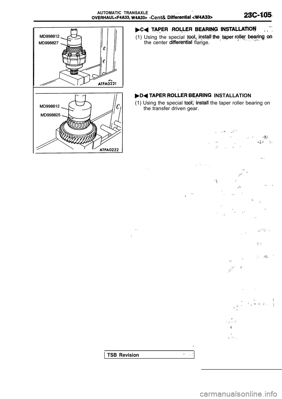
(1) Using the special
the center flarige.
INSTALLATION
(1) Using the special
the taper roller bearing on
the transfer driven gear.
.
,
.
TSB Revision
Page 1390 of 2103
AUTOMATIC TRANSAXLE
Front Output Shaft ,
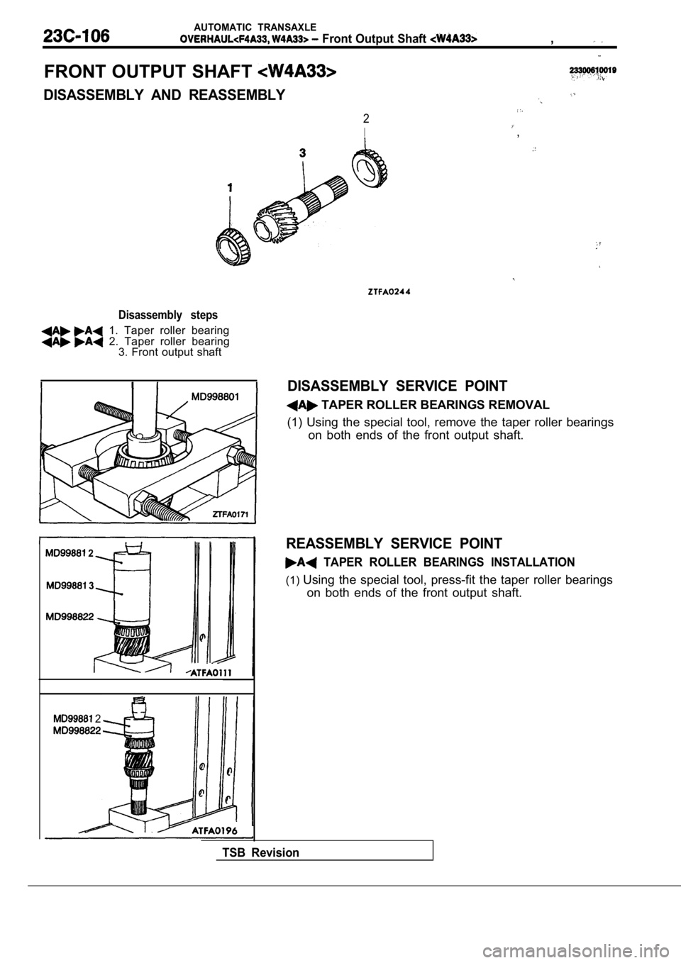
FRONT OUTPUT SHAFT
DISASSEMBLY AND REASSEMBLY
2
I,
Disassembly steps
1. Taper roller bearing 2. Taper roller bearing3. Front output shaft
2
3
2
DISASSEMBLY SERVICE POINT
TAPER ROLLER BEARINGS REMOVAL
(1) Using the special tool, remove the taper roller bearings
on both ends of the front output shaft.
REASSEMBLY SERVICE POINT
TAPER ROLLER BEARINGS INSTALLATION
(1) Using the special tool, press-fit the taper roller bearings
on both ends of the front output shaft.
TSB Revision
Trending: fuel pressure, set clock, torque, wheel, headlights, seats, ad blue
