MITSUBISHI SPYDER 1990 Service Repair Manual
SPYDER 1990
MITSUBISHI
MITSUBISHI
https://www.carmanualsonline.info/img/19/57345/w960_57345-0.png
MITSUBISHI SPYDER 1990 Service Repair Manual
Trending: turn signal, wiring, battery capacity, fuel consumption, air filter, inflation pressure, alarm
Page 1631 of 2103
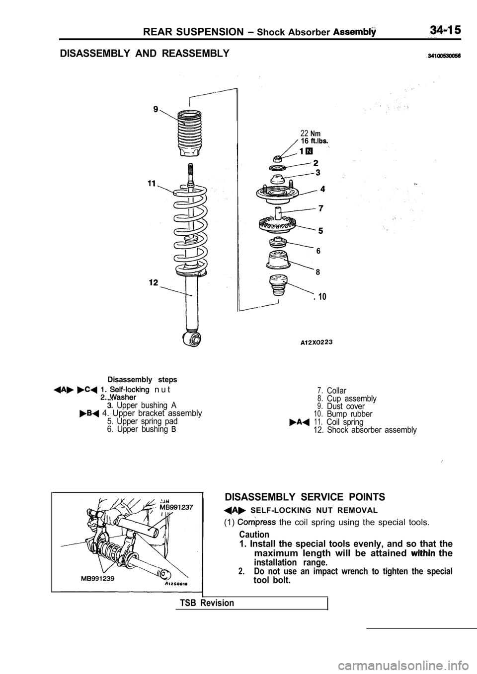
REAR SUSPENSION Shock Absorber
DISASSEMBLY AND REASSEMBLY
Disassembly steps
n u t
Upper bushing A 4. Upper bracket assembly
5. Upper spring pad
6. Upper bushing
22Nm16
6
8
. 10
7.Collar8.Cup assembly9.Dust cover10.Bump rubber11.Coil spring
12. Shock absorber assembly
DISASSEMBLY SERVICE POINTS
SELF-LOCKING NUT REMOVAL
(1)
the coil spring using the special tools.
Caution
1. Install the special tools evenly, and so that th e
maximum length will be attained the
installation range.
2.Do not use an impact wrench to tighten the special
tool bolt.
TSB Revision
Page 1632 of 2103
REAR SUSPENSION Shock
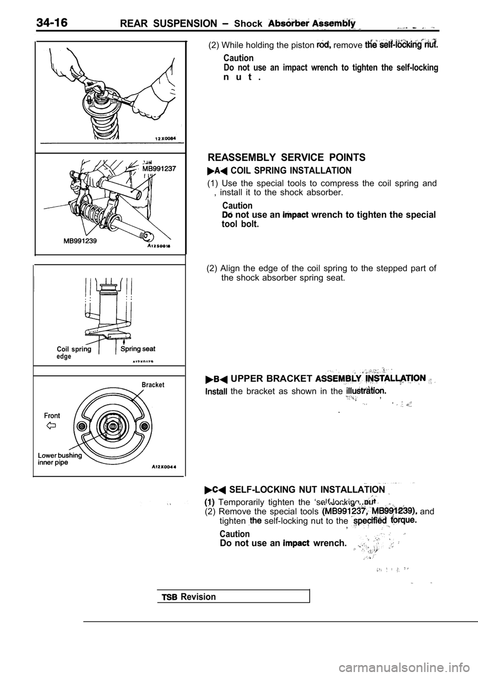
Coil spriedgeBracket
(2) While holding the piston remove
Caution
Do not use an impact wrench to tighten the self-loc king
n u t .
REASSEMBLY SERVICE POINTS
COIL SPRING INSTALLATION
(1) Use the special tools to compress the coil spring and
, install it to the shock absorber.
Caution
not use an wrench to tighten the special
tool bolt.
(2) Align the edge of the coil spring to the steppe d part of
the shock absorber spring seat.
UPPER BRACKET
the bracket as shown in the ,
.
SELF-LOCKING NUT INSTALLATION
Temporarily tighten the ‘self-locking
(2) Remove the special tools and
tighten
self-locking nut to the ,
Caution
Do not use an wrench.
Revision
Page 1633 of 2103
REAR
INSPECTION
l Check the rubber parts
lCheck the coil springs for crack, deterioration.
,
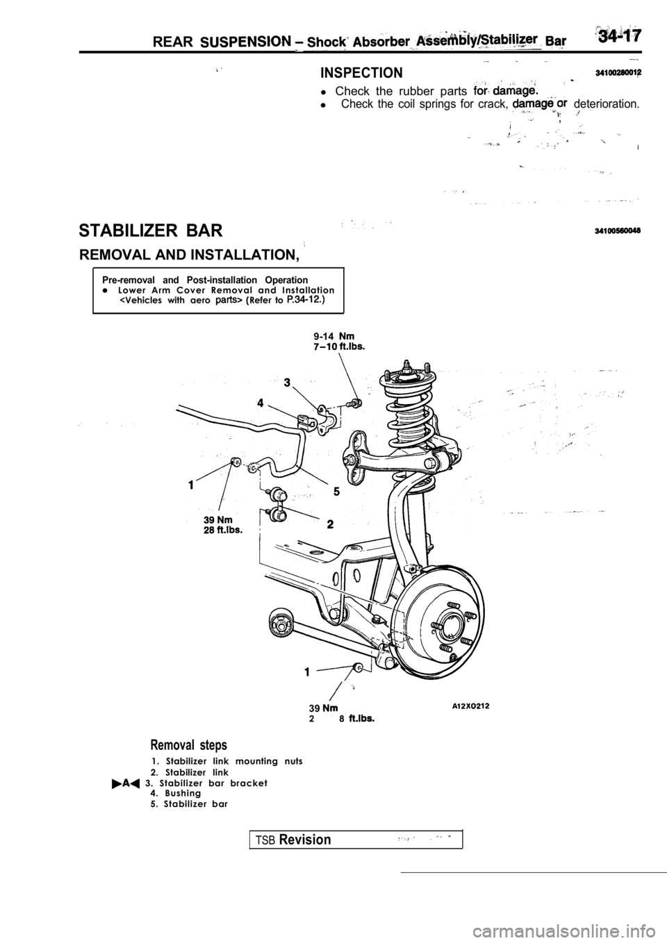
STABILIZER BAR
REMOVAL AND INSTALLATION,
Pre-removal and Post-installation Operationl L o w e r A r m C o v e r R e m o v a l a n d I n s t a l l a t i o n
9-14
392 8
Removal steps
1. Stabilizer link mounting nuts
2. Stabilizer link
3 . S t a b i l i z e r b a r b r a c k e t 4 . B u s h i n g
5 . S t a b i l i z e r b a r
TSBRevision
Page 1634 of 2103
S U S P E N S I O N B a r
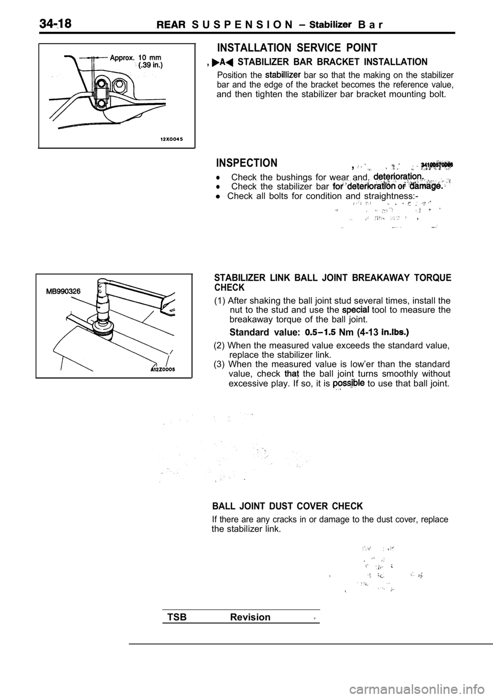
INSTALLATION SERVICE POINT
, STABILIZER BAR BRACKET INSTALLATION
Position the bar so that the making on the stabilizer
bar and the edge of the bracket becomes the referen ce value,
and then tighten the stabilizer bar bracket mounting bolt.
INSPECTION,
lCheck the bushings for wear and,
lCheck the stabilizer bar
l Check all bolts for condition and straightness:- .
. . ,
STABILIZER LINK BALL JOINT BREAKAWAY TORQUE
CHECK
(1) After shaking the ball joint stud several times , install the
nut to the stud and use the
tool to measure the
breakaway torque of the ball joint.
Standard value: Nm (4-13
(2) When the measured value exceeds the standard va lue,
replace the stabilizer link.
(3) When the measured value is low’er than the stan dard
value, check
the ball joint turns smoothly without
excessive play. If so, it is
to use that ball joint.
BALL JOINT DUST COVER CHECK
If there are any cracks in or damage to the dust co ver, replace
the stabilizer link.
TSB Revision
Page 1635 of 2103
REAR SUSPENSION Stabilizer Bar
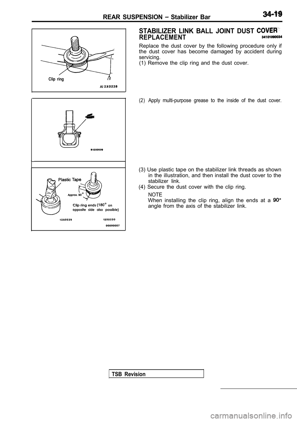
STABILIZER LINK BALL JOINT DUST
REPLACEMENT
Replace the dust cover by the following procedure only if
the dust cover has become damaged by accident durin g
servicing.
(1) Remove the clip ring and the dust cover.
Clip ring
Al
Clip ring ends on
opposite side also possible)
(2)Apply multi-purpose grease to the inside of the dus t cover.
(3) Use plastic tape on the stabilizer link threads as shown
in the illustration, and then install the dust cove r to the
stabilizer link.
(4) Secure the dust cover with the clip ring.
NOTE
When installing the clip ring, align the ends at a
angle from the axis of the stabilizer link.
TSB Revision
Page 1636 of 2103
Page 1637 of 2103
SERVICE BRAKES
CONTENTS
BASIC BRAKE SYSTEM. . . . . . . . . . . . . . . . . . . . . . . . . . . . . . . . . . . . . . . . . . . . . . . .
ANTI-LOCK BRAKING SYSTEM (ABS) . . . . . . . . . . . . . . . . . . . . . . . . . . .358
ANTI-LOCK BRAKING SYSTEM (ABS) . . . . . . . . . . . . . . . . . . . . . . . . . . .
Page 1638 of 2103
Page 1639 of 2103
B R A K E
S Y S T E M
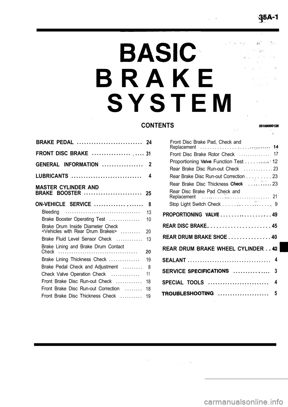
CONTENTS
BRAKE PEDAL. . . . . . . . . . . . . . . . . . . . . . . . . . .24
FRONT DISC BRAKE. . . . . . . . . . . . . . . .,. . . .31
GENERAL INFORMATION. . . . . . . . . . . . . . . . .2
LUBRICANTS. . . . . . . . . . . . . . . . . . . . . . . . . . . . .4
MASTER CYLINDER AND
BRAKE BOOSTER. . . . . . . . . . . . . . . . . . . . . . . .25
ON-VEHICLE SERVICE
. . . . . . . . . . . . .. . . . . .8
Bleeding. . . . . . . . . . . . . . . . . . . . . . . . . . . . . . . . . .13
Brake Booster Operating Test. . . . . . . . . . . . . .10
Brake Drum Inside Diameter Check
. . . . . . . . .20
Brake Fluid Level Sensor Check. . . . . . . . . . . .13
Brake Lining and Brake Drum Contact
Check. . . . . . . . . . . . . . . . . . . . . . . . . . . . . . . . . . . .
Brake Lining Thickness Check. . . . . . . . . . . . . .19
Brake Pedal Check and Adjustment. . . . . . . . .8
Check Valve Operation Check. . . . . . . . . . . . .11
Front Brake Disc Run-out Check. . . . . . . . . . . .18
Front Brake Disc Run-out Correction. . . . . . . .18
Front Brake Disc Thickness Check. . . . . . . . . .19
Front Disc Brake Pad, Check and
Replacement. . . . . . . . . . . . . . . . . . .
Front Disc Brake Rotor Check. . . . . . . . . . . . . .17
Proportioning Function Test . . . . . 12
Rear Brake Disc Run-out Check. . . . . . . . . . . . 23
Rear Brake Disc Run-out Correction . . . . . . . . . 23
Rear Brake Disc Thickness
. . . 23
Rear Disc Brake Pad Check and
Replacement. . . . . . . . . . . . . . . . . . . . . . . . . 21
Stop Light Switch Check . . . . . . . . . . . . . 9
PROPORTIONING . . . . . . . . . . . . . . . . 49
REAR DISC BRAKE.. . . . . . . . . . . . . . . . . . . . . . 45
REAR DRUM BRAKE SHOE . . . . . . . . . . . . . . . 40
REAR DRUM BRAKE WHEEL CYLINDER .
SEALANT. . . . . . . . . . . . . . . . . . . . . . . . . . . . . . . . . .4
SERVICE. . . . . . . . . .. . . .3
SPECIAL TOOLS. . . . . . . . . . . . . . . . . . . . . . . . .4
. . . . . . . . . . . . . . . . . . . . .5
Page 1640 of 2103
BRAKE SYSTEM General Information
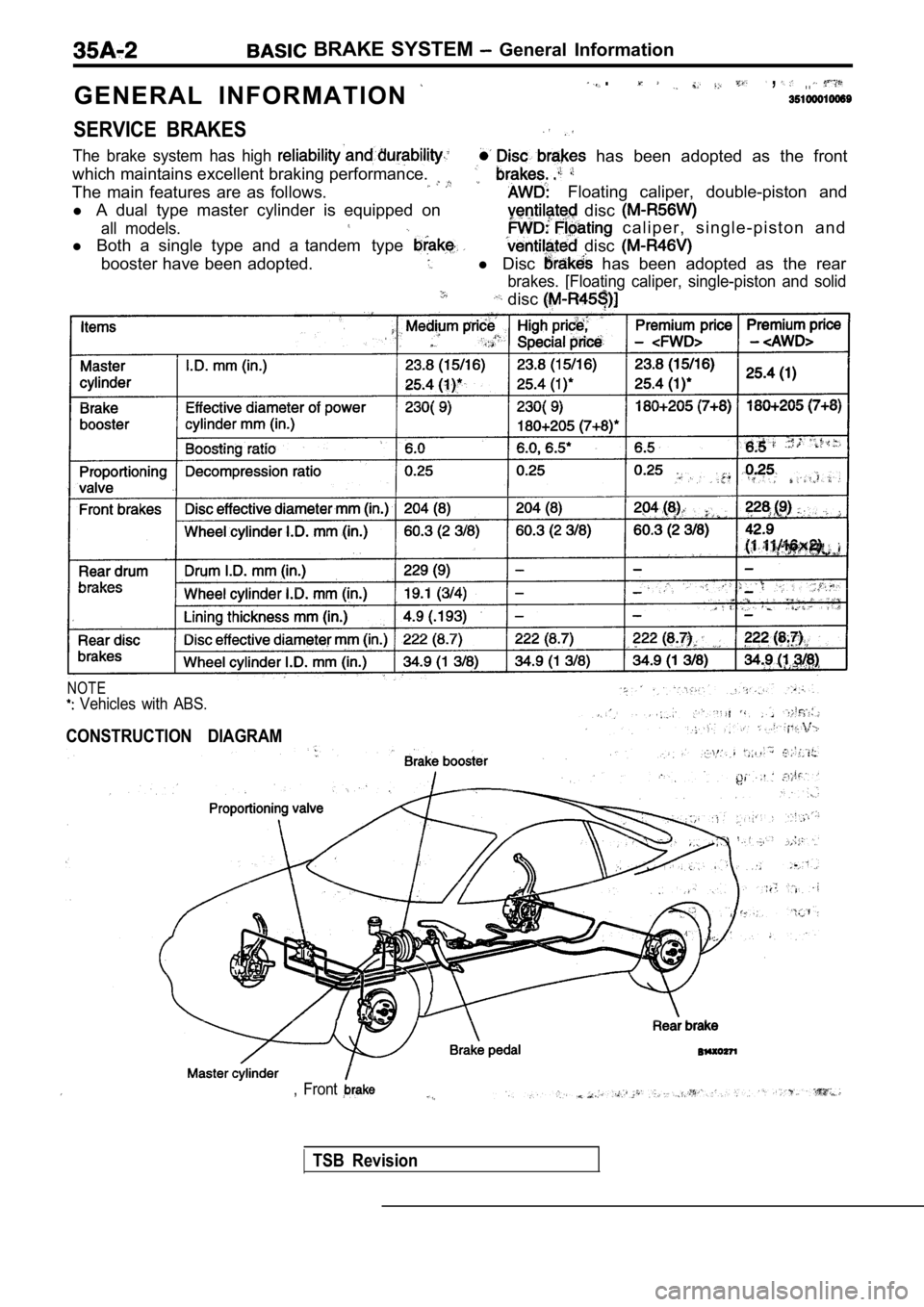
G E N E R A L I N F O R M A T I O N
. , . .
SERVICE BRAKES
The brake system has high
which maintains excellent braking performance.
has been adopted as the front
The main features are as follows. Floating caliper, double-piston and
l A dual type master cylinder is equipped on
disc
all models.
l Both a single type and a tandem type
c a l i p e r , s i n g l e - p i s t o n a n d
disc
booster have been adopted.l Disc has been adopted as the rear
brakes. [Floating caliper, single-piston and solid
disc
NOTE
Vehicles with ABS.
CONSTRUCTION DIAGRAM
, Front
TSB Revision
Trending: fog light, air bleeding, jack points, maintenance reset, oil capacities, adding oil, warning lights
