MITSUBISHI SPYDER 1990 Service Repair Manual
Manufacturer: MITSUBISHI, Model Year: 1990, Model line: SPYDER, Model: MITSUBISHI SPYDER 1990Pages: 2103, PDF Size: 68.98 MB
Page 1651 of 2103
BASIC BRAKE SYSTEM
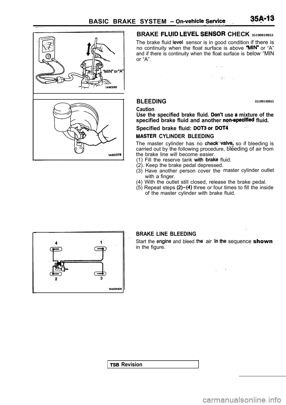
BRAKE CHECK 35190919953
The brake fluid
sensor is in good condition if there is
no continuity when the float surface is above
or “A”
and if there is continuity when the float surface i s below “MIN
or “A”.
BLEEDING
Caution
35199149955
Use the specified brake fluid. use mixture of the
specified brake fluid and another fluid.
Specified brake fluid:
CYLINDER BLEEDING
The master cylinder has no so if bleeding is
carried out by the following procedure, bleeding of air from
the brake line will become easier. (1) Fill the reserve tank
fluid.
(2). Keep the brake pedal depressed.
(3) Have another person cover the master cylinder outlet
with a finger.
(4) With the outlet still closed, release the brake pedal.
(5) Repeat steps
three or four times to fill the inside
of the master cylinder with brake fluid.
BRAKE LINE BLEEDING
Start the and bleed air sequence shown
in the figure.
Revision
Page 1652 of 2103
4 SYSTEM Service
Pad
indicator
Brake disc
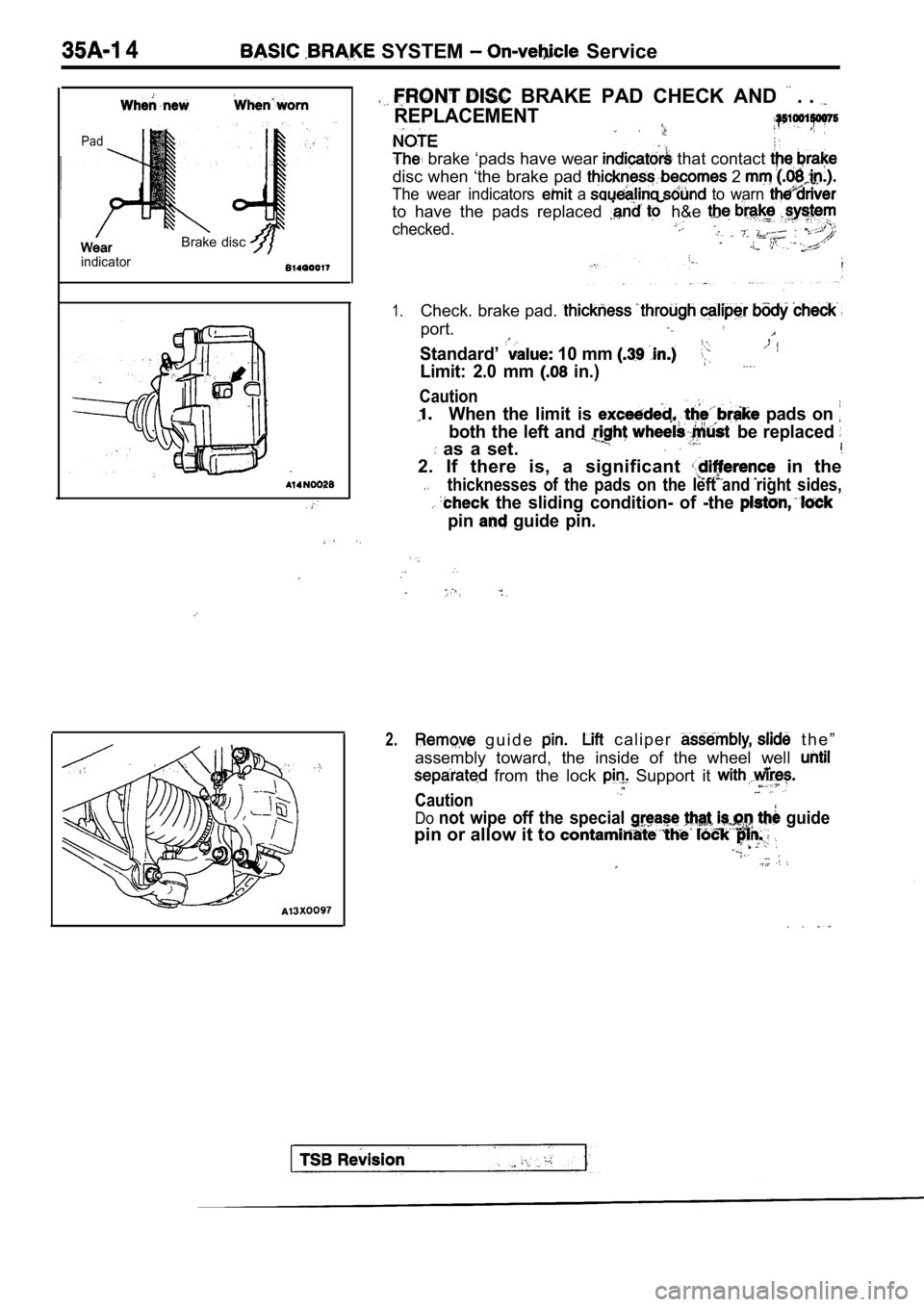
BRAKE PAD CHECK AND . .
REPLACEMENT
brake ‘pads have wear that contact
disc when ‘the brake pad 2
The wear indicators a to warn
to have the pads replaced h&e
checked.
1.Check. brake pad.
port.
Standard’ 10 mm
,
Limit: 2.0 mm in.)
Caution
When the limit is pads on
both the left and be replaced
as a set.
2. If there is, a significant in the
thicknesses of the pads on the left and right sides,
the sliding condition- of -the
pin guide pin.
2. g u i d e c a l i p e r t h e ”
assembly toward, the inside of the wheel well
from the lock Support it
Caution
Donot wipe off the special guide
pin or allow it to
Page 1653 of 2103
BASIC BRAKE SYSTEM
Front hub assembly
196-255 Nm
145-188
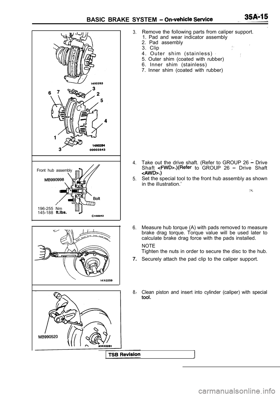
3.
4.
5.
6.
8.
Remove the following parts from caliper support. 1. Pad and wear indicator assembly
2. Pad assembly
3. Clip
4 . O u t e r s h i m ( s t a i n l e s s )
5. Outer shim (coated with rubber)
6. Inner shim (stainless)
7. Inner shim (coated with rubber)
Take out the drive shaft. (Refer to GROUP 26
Drive
Shaft
to GROUP 26 Drive Shaft
Set the special tool to the front hub assembly as s hown
in the illustration.’
Measure hub torque (A) with pads removed to measure
brake drag torque. Torque value will be used later to
calculate brake drag force with the pads installed.
NOTE
Tighten the nuts in order to secure the disc to the hub.
Securely attach the pad clip to the caliper support .
Clean piston and insert into cylinder (caliper) with special
Page 1654 of 2103
BASIC BRAKE SYSTEM On-vehicle Service
Pad assembly
Grease
Grease Al
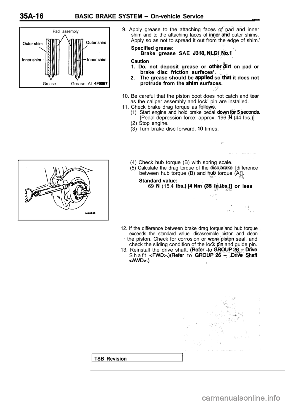
9. Apply grease to the attaching faces of pad and i nner
shim and to the attaching faces of outer shims.
Apply so as not to spread it out from the edge of shim.’
Specified grease:
Brake grease SAE
Caution
1. Do, not deposit grease or on pad or
brake disc friction surfaces’.
2.The grease should be so it does not
protrude from the
surfaces.
10. Be careful that the piston boot does not catch and
as the caliper assembly and lock’ pin are installed.
11. Check brake drag torque as
(1)Start engine and hold brake pedal
[Pedal depression force: approx. 196 (44 Ibs.)]
(2) Stop engine.
(3) Turn brake disc forward.
times,
(4) Check hub torque (B) with spring scale.
(5) Calculate the drag torque of the [difference
between hub torque (B) and torque (A)]. .
Standard value:
69 (15.4 or less,
12. If the difference between brake drag torque’and hub torque
exceeds the standard value, disassemble piston and clean
the piston. Check for corrosion or seal, and
check the sliding condition of the lock
and guide pin.
13. Reinstall the drive shaft.
-to
S h a f t t o
TSB Revision
Page 1655 of 2103
B R A K E S Y S T E M 7 .
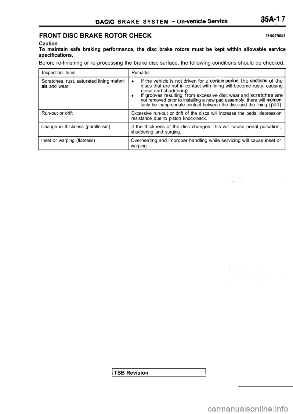
FRONT DISC BRAKE ROTOR CHECK
35100270047
Caution
To maintain safe braking performance, the disc brak e rotors must be kept within allowable service
specifications.
Before re-finishing or re-processing the brake disc surface, the following conditions should be checke d.
Inspection itemsRemarks
Scratches, rust, saturated lining lIf the vehicle is not driven for a the of the
and weardiscs that are not in contact with lining will beco me rusty, causing
noise and shudderin.lIf grooves resultingrom excessive disc wear and scratches arenot removed prior to installing a new pad assembly, there will tarily be inappropriate contact between the disc and the lining (pad).
Run-out or drift
Excessive run-out or drift of the discs will increa se the pedal depression
resistance due to piston knock-back.
Change in thickness (parallelism)
If the thickness of the disc changes, this will cau se pedal pulsation,
shuddering and surging.
Inset or warping (flatness)
Overheating and improper handling while servicing w ill cause inset or
warping.
TSB Revision
Page 1656 of 2103
BASIC BRAKE SYSTEM On-vehicle Service
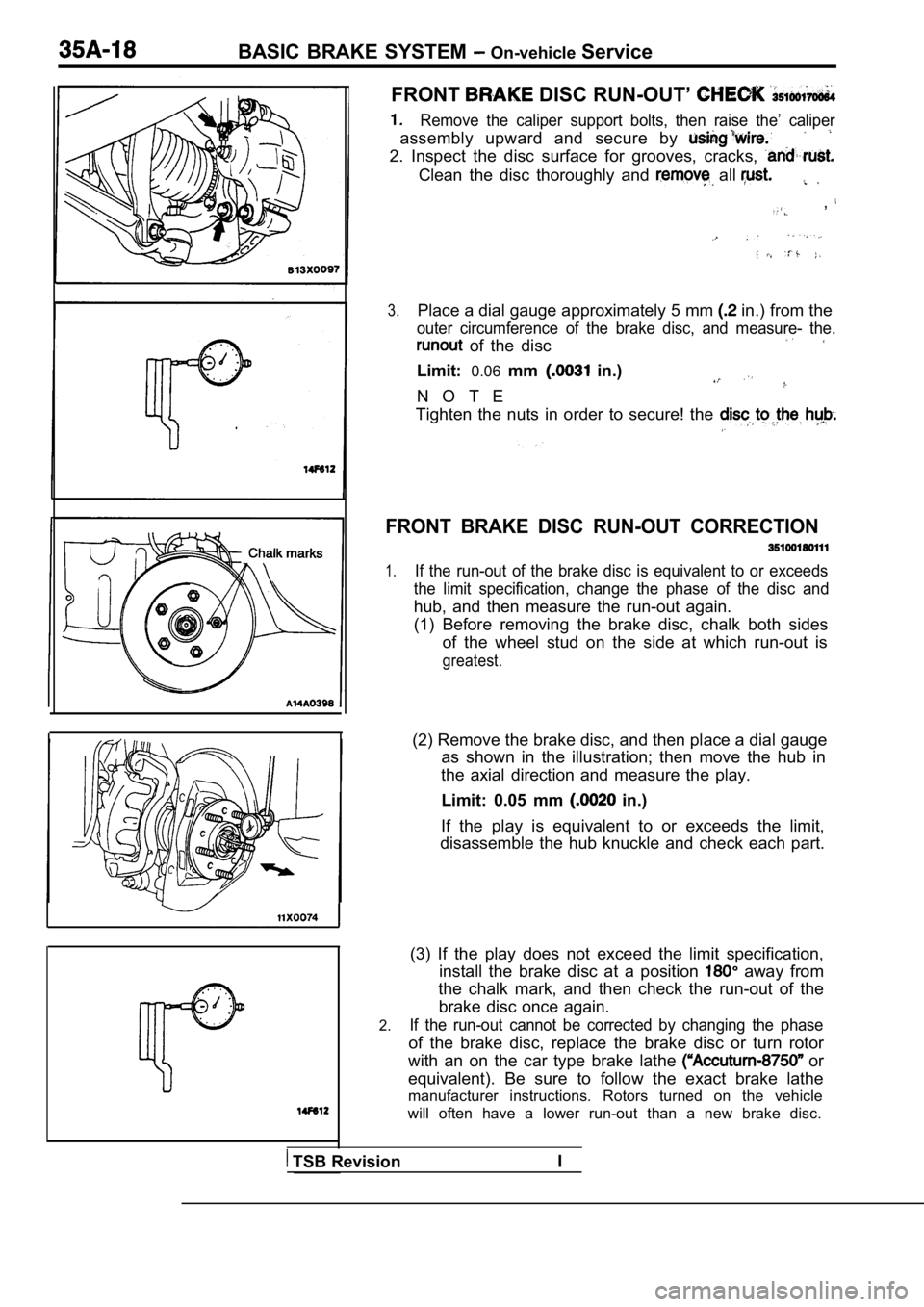
FRONT DISC RUN-OUT’
Remove the caliper support bolts, then raise the’ c aliper
assembly upward and secure by
2. Inspect the disc surface for grooves, cracks,
Clean the disc thoroughly and all
,
3.Place a dial gauge approximately 5 mm in.) from the
outer circumference of the brake disc, and measure- the.
of the disc
Limit:0.06mm in.)
N O T E
Tighten the nuts in order to secure! the
FRONT BRAKE DISC RUN-OUT CORRECTION
1.If the run-out of the brake disc is equivalent to o r exceeds
the limit specification, change the phase of the di sc and
hub, and then measure the run-out again.
(1) Before removing the brake disc, chalk both side s
of the wheel stud on the side at which run-out is
greatest.
(2) Remove the brake disc, and then place a dial ga uge
as shown in the illustration; then move the hub in
the axial direction and measure the play.
Limit: 0.05 mm
in.)
If the play is equivalent to or exceeds the limit,
disassemble the hub knuckle and check each part.
2.
(3) If the play does not exceed the limit specifica tion,
install the brake disc at a position
away from
the chalk mark, and then check the run-out of the
brake disc once again.
If the run-out cannot be corrected by changing the phase
of the brake disc, replace the brake disc or turn rotor
with an on the car type brake lathe
or
equivalent). Be sure to follow the exact brake lath e
manufacturer instructions. Rotors turned on the veh icle
will often have a lower run-out than a new brake di sc.
TSB RevisionI
Page 1657 of 2103
BASIC On-vehicle Service
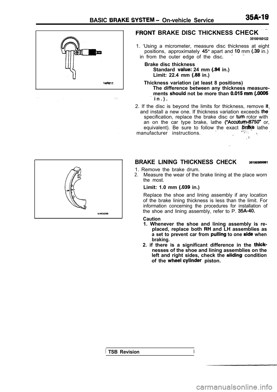
BRAKE DISC THICKNESS CHECK
35100160122
1. ‘Using a micrometer, measure disc thickness at e ight
positions, approximately
apart and mm in.)
in from the outer edge of the disc.
Brake disc thickness Standard
24 mm in.)
Limit: 22.4 mm
in.)
Thickness variation (at least 8 positions) The difference between any thickness measure-
ments
not be more than
i n . ) .
2. If the disc is beyond the limits for thickness, remove
and install a new one. If thickness variation excee ds
specification, replace the brake disc or rotor with
an on the car type brake, lathe
or,
equivalent). Be sure to follow the exact
lathe
manufacturer instructions.
BRAKE LINING THICKNESS CHECK
1. Remove the brake drum.
2.Measure the wear of the brake lining at the place w orn
the most.
Limit: 1.0 mm in.)
Replace the shoe and lining assembly if any locatio n
of the brake lining thickness is less than the limi t. For
information concerning the procedures for installat ion of
the shoe and lining assembly, refer to P.
Caution
1. Whenever the shoe and lining assembly is re-
placed, replace both
and LH assemblies as
a set to prevent car from to one when
braking.
2. if there is a significant difference in the
nesses of the shoe and lining assemblies on the
left and right sides, check the
condition
of the
piston.
TSB RevisionI
Page 1658 of 2103
B A S I C B R A K E S Y S T E M . .
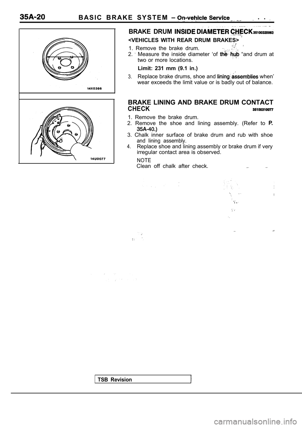
BRAKE DRUM
1. Remove the brake drum.
2. Measure the inside diameter ‘of “and drum at
two or more locations.
Limit: 231 mm (9.1 in.)
3.Replace brake drums, shoe and when’
wear exceeds the limit value or is badly out of bal ance.
BRAKE LINING AND BRAKE DRUM CONTACT
CHECK
1. Remove the brake drum.
2. Remove the shoe and lining assembly. (Refer to
3. Chalk inner surface of brake drum and rub with s hoe
and lining assembly.
4.Replace shoe and lining assembly or brake drum if very
irregular contact area is observed.
NOTE
Clean off chalk after check.
TSB Revision
. .
Page 1659 of 2103
BASIC BRAKE SYSTEM
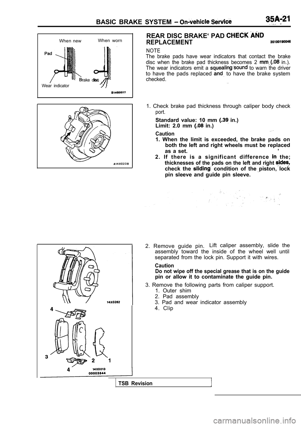
When newWhen worn
rake disc
Wear indicator
1 REAR DISC BRAKE‘ PAD
REPLACEMENT
NOTE
The brake pads have wear indicators that contact th
e brake
disc when the brake pad thickness becomes 2
in.).
The wear indicators emit a
to warn the driver
to have the pads replaced to have the brake system
checked.. .
1. Check brake pad thickness through caliper body c heck
port.
Standard value: 10 mm in.)
Limit: 2.0 mm
in.)
Caution
1. When the limit is exceeded, the brake pads on
both the left and right wheels must be replaced
as a set. ,
2 . I f t h e r e i s a s i g n i f i c a n t d i f f e r e n c e
the;
thicknesses of the pads on the left and right
check the condition of the piston, lock
pin sleeve and guide pin sleeve.
2. Remove guide pin. Lift caliper assembly, slide the
assembly toward the inside of the wheel well until
separated from the lock pin. Support it with wires.
Caution Do not wipe off the special grease that is on the g uide
pin or allow it to contaminate the guide pin.
3. Remove the following parts from caliper support. 1. Outer shim
2. Pad assembly
3. Pad and wear indicator assembly
4. Clip
TSB Revision
Page 1660 of 2103
BASIC BRAKE SYSTEM On-vehicle Service
TSB Revision
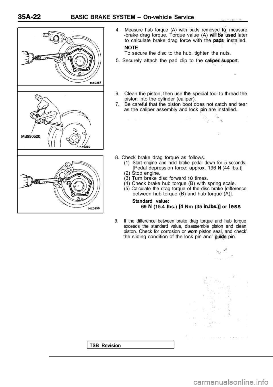
4.Measure hub torque (A) with pads removed measure
-brake drag torque. Torque value (A) later
to calculate brake drag force with the
installed.
To secure the disc to the hub, tighten the nuts.
5. Securely attach the pad clip to the
6.Clean the piston; then use special tool to thread the
piston into the cylinder (caliper).
7.Be careful that the piston boot does not catch and tear
as the caliper assembly and lock
are installed.
8. Check brake drag torque as follows.
(1) Start engine and hold brake pedal down for 5 second
s.
[Pedal depression force: approx. 196 (44 Ibs.)]
(2) Stop engine.
(3) Turn brake disc forward
times.
(4) Check brake hub torque (B) with spring scale.
(5) Calculate the drag torque of the disc brake [di fference
between hub torque (B) and hub torque (A)].
Standard value:
69 (15.4 Ibs.) Nm (35 or less
9.If the difference between brake drag torque and hub torque
exceeds the standard value, disassemble piston and clean
piston. Check for corrosion or piston seal, and check’
the sliding condition of the lock pin and’ pin.