MITSUBISHI SPYDER 1990 Service Repair Manual
SPYDER 1990
MITSUBISHI
MITSUBISHI
https://www.carmanualsonline.info/img/19/57345/w960_57345-0.png
MITSUBISHI SPYDER 1990 Service Repair Manual
Trending: tire type, charging, service schedule, automatic transmission fluid, lock, belt, engine coolant
Page 2081 of 2103
and Tension
Engine (Non-turbo)>
Bolt mm in.)]
Socket
Deep socket
(14 mm
in.)]
TSB
HUB REMOVAL
(1) Remove the clutch hub mounting bolt.
(2) Tighten a
mm in.) bolt into the hole of the
clutch hub to remove the serration assembly the shaft
and the clutch hub.
SEAL INSTALLATION
Use a 21 mm in.) socket to install the shaft seal so
that the O-ring assembly side is facing the front h ousing.
FELT, FELT HOLDER INSTALLATION
After installing the felt in the felt holder, them to the
front housing using a 14 mm
deep socket.
FRONT HOUSING INSTALLATION
(1) Apply compressor oil to the shaft.
Compressor oil: ND-OIL 8
(2) Install the front housing without damaging the shaft seal
lip.
(3) After installing the front housing, install the clutch hub
mounting bolt to the shaft, and check that the breakaway
torque is within the torque value.
Breakaway torque:
Nm (4 or less
Page 2082 of 2103
55-42
Pin
Main unit of conditioningcompressor
Compressor side
connector
2
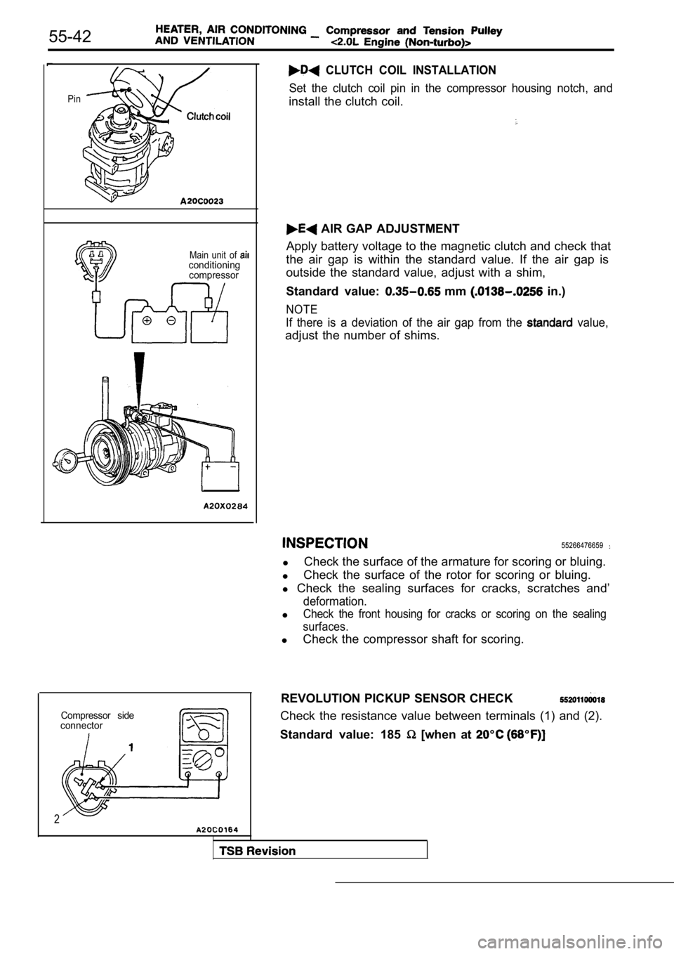
CLUTCH COIL INSTALLATION
Set the clutch coil pin in the compressor housing n otch, and
install the clutch coil.
AIR GAP ADJUSTMENT
Apply battery voltage to the magnetic clutch and ch eck that
the air gap is within the standard value. If the ai r gap is
outside the standard value, adjust with a shim,
Standard value:
mm in.)
NOTE
If there is a deviation of the air gap from the value,
adjust the number of shims.
55266476659
l Check the surface of the armature for scoring or bl
uing.
l Check the surface of the rotor for scoring or bluin
g.
l Check the sealing surfaces for cracks, scratches an d’
deformation.
lCheck the front housing for cracks or scoring on the sealing
surfaces.
l Check the compressor shaft for scoring.
REVOLUTION PICKUP SENSOR CHECK
Check the resistance value between terminals (1) an d (2).
Standard value: 185
[when at
Page 2083 of 2103
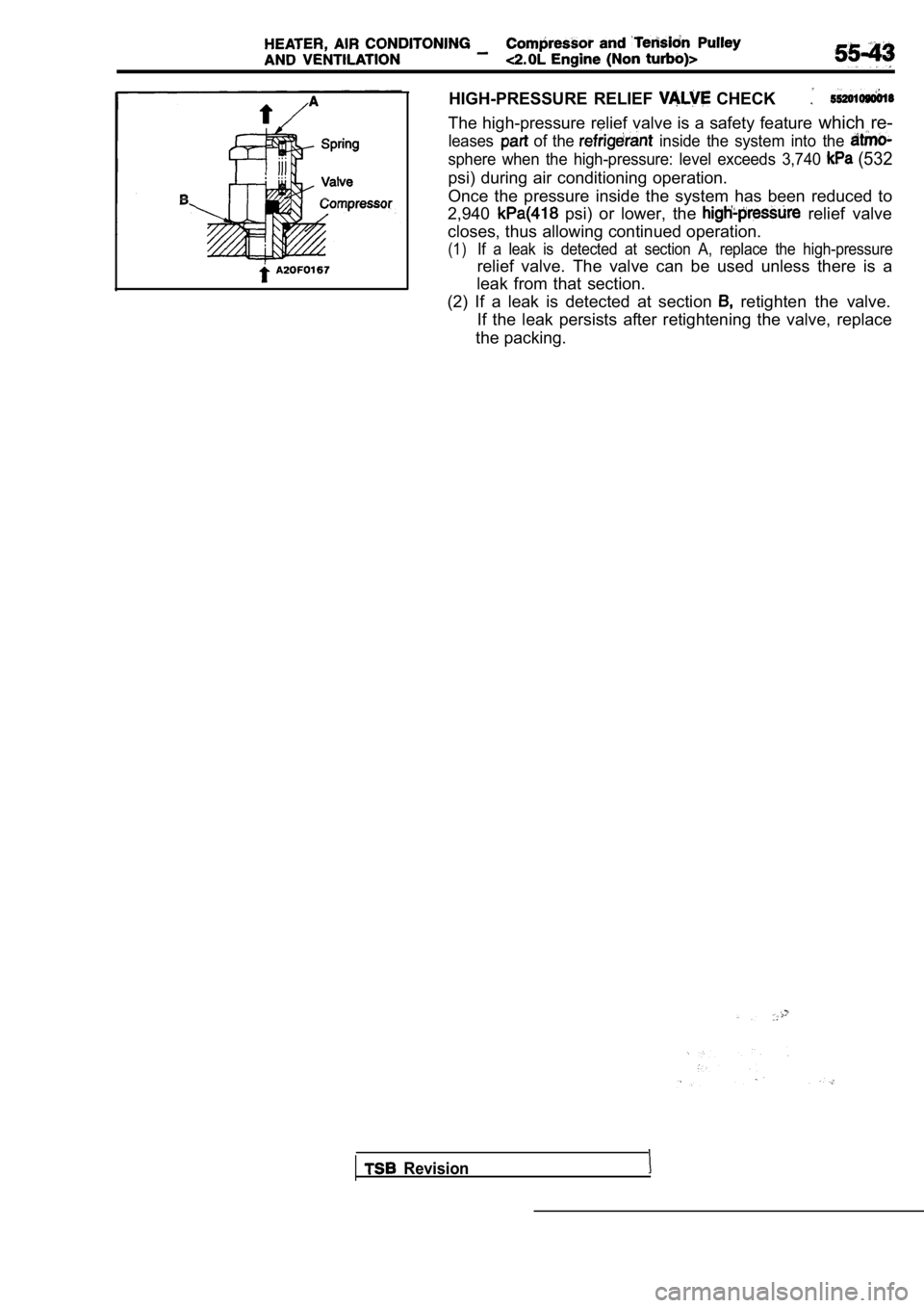
HIGH-PRESSURE RELIEF CHECK
The high-pressure relief valve is a safety feature which re-
leases of the inside the system into the
sphere when the high-pressure: level exceeds 3,740 (532
psi) during air conditioning operation.
Once the pressure inside the system has been reduce d to
2,940
psi) or lower, the relief valve
closes, thus allowing continued operation.
(1)If a leak is detected at section A, replace the hig h-pressure
relief valve. The valve can be used unless there is a
leak from that section.
(2) If a leak is detected at section
retighten the valve.
If the leak persists after retightening the valve, replace
the packing.
Revision
Page 2084 of 2103
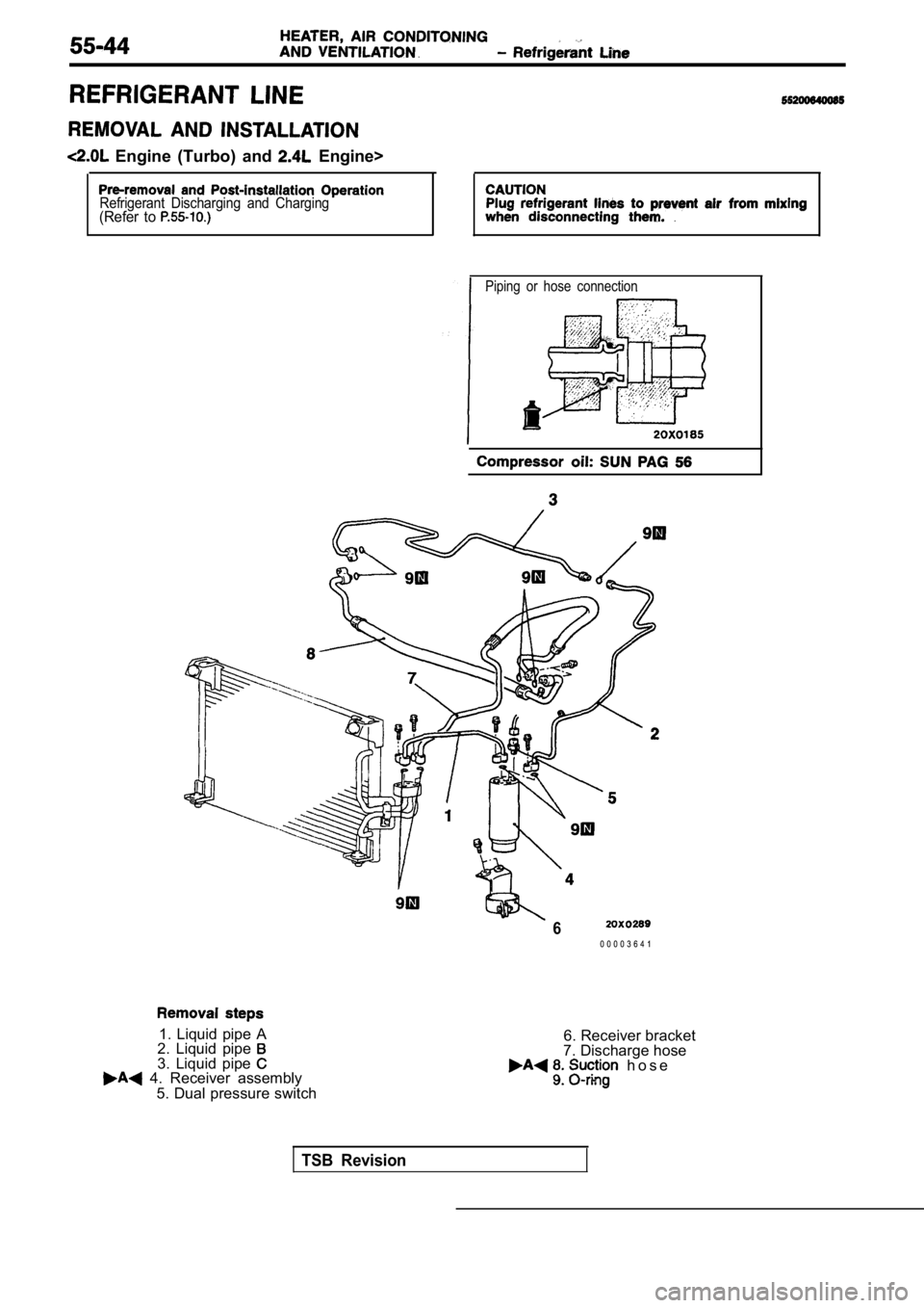
Engine (Turbo) and Engine>
Refrigerant Discharging and Charging(Refer to
Piping or hose connection
1. Liquid pipe A
2. Liquid pipe
3. Liquid pipe 4. Receiver assembly
5. Dual pressure switch
60 0 0 0 3 6 4 1
6. Receiver bracket
7. Discharge hose
h o s e
.
TSB Revision
Page 2085 of 2103
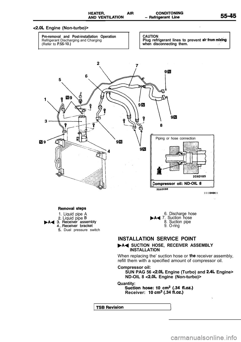
Engine (Non-turbo)>
Pm-removal and Post-installation OperationRefrigerant Discharging and Charging
(Refer to CAUTIONPlug refrigerant lines to prevent when disconnecting them.
Piping or hose connection
0 0 0 0 4 0 6 9
1. Liquid pipe A
Liquid pipe
Dual pressure switch
6. Discharge hose 7. Suction hose
8. Suction pipe9. O-ring
INSTALLATION SERVICE POINT
SUCTION HOSE, RECEIVER ASSEMBLYINSTALLATION
When replacing the’ suction hose or receiver assembly,
refill them with a specified amount of compressor o il.
Compressor oil: SUN PAG 56
Engine (Turbo) and Engine>
ND-OIL 8
Engine (Non-turbo)>
Quantity:
Receiver:
Page 2086 of 2103
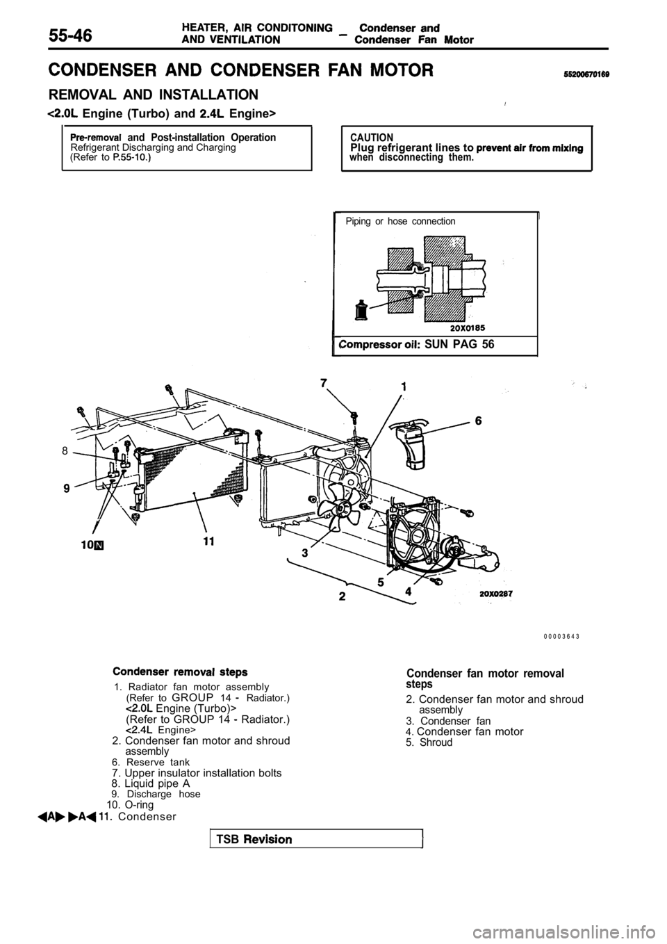
REMOVAL AND INSTALLATION
Engine (Turbo) and Engine>
and Post-installation OperationRefrigerant Discharging and Charging
(Refer to CAUTIONPlug refrigerant lines to when disconnecting them.
Piping or hose connection
SUN PAG 56
1. Radiator fan motor assembly
(Refer to GROUP 14 Radiator.) Engine (Turbo)>
(Refer to GROUP 14 Radiator.) Engine>
2. Condenser fan motor and shroud
assembly6. Reserve tank
7. Upper insulator installation bolts
8. Liquid pipe A
9. Discharge hose
10. O-ring
Condenser
8
0 0 0 0 3 6 4 3
Condenser fan motor removalsteps
2. Condenser fan motor and shroudassembly
3. Condenser fan
4. Condenser fan motor5. Shroud
TSB
Page 2087 of 2103
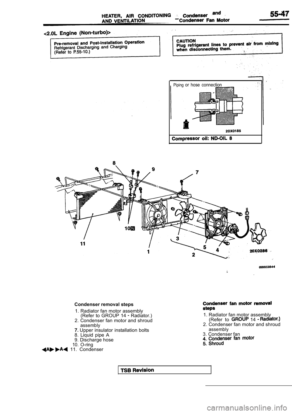
Pipingor hose connection
Condenser removal steps1. Radiator fan motor assembly (Refer to GROUP 14
Radiator.)
2. Condenser fan motor and shroud
assembly Upper insulator installation bolts
8. Liquid pipe A
9. Discharge hose
10. O-ring 11. Condenser
1. Radiator fan motor assembly (Refer to 14 2. Condenser fan motor and shroud
assembly3. Condenser fan
Page 2088 of 2103
HEATER, AIR Condenser and
Condenser Fan’ Motor
TurboNon-turbo
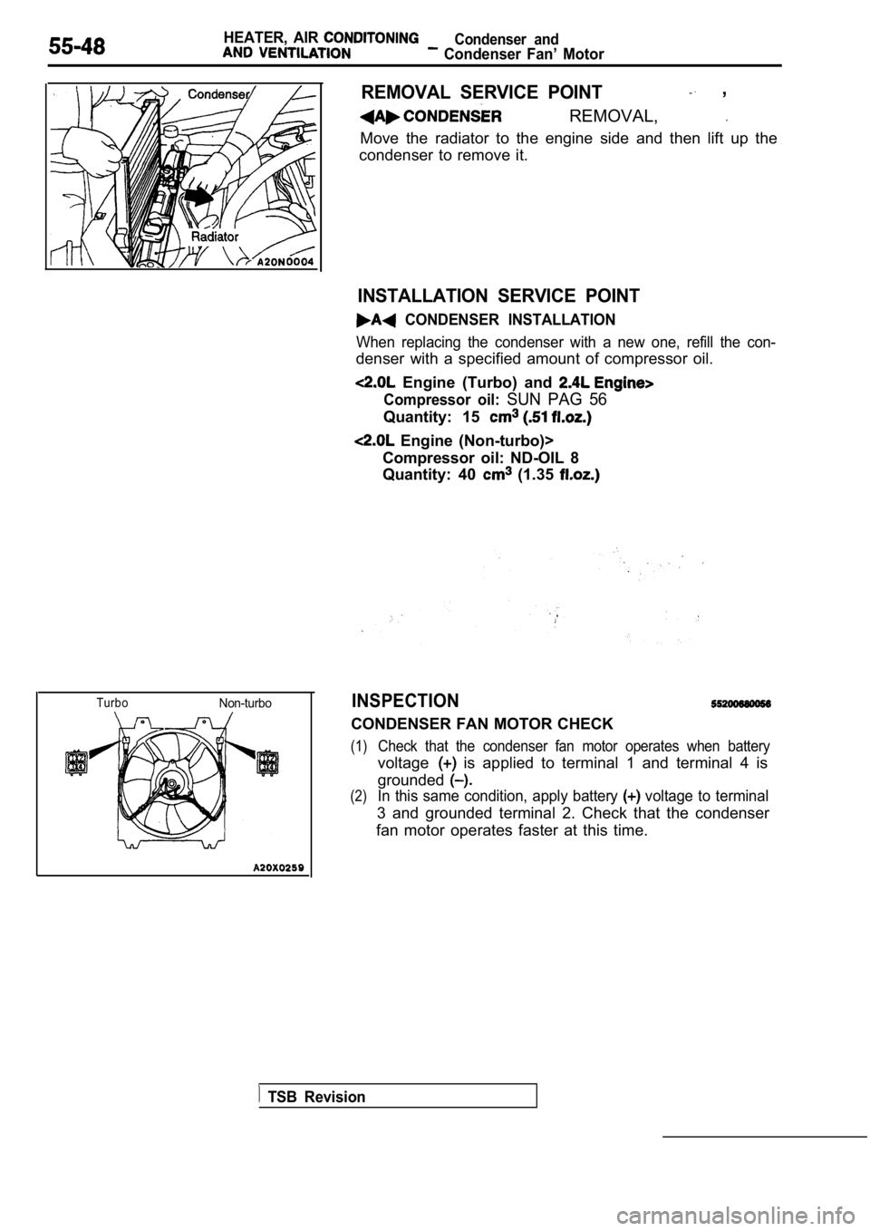
REMOVAL SERVICE POINT ,
REMOVAL,
Move the radiator to the engine side and then lift up the
condenser to remove it.
INSTALLATION SERVICE POINT
CONDENSER INSTALLATION
When replacing the condenser with a new one, refill the con-
denser with a specified amount of compressor oil.
Engine (Turbo) and
Compressor oil: SUN PAG 56
Quantity: 15
Engine (Non-turbo)>
Compressor oil: ND-OIL 8
Quantity: 40
(1.35
INSPECTION
CONDENSER FAN MOTOR CHECK
(1)Check that the condenser fan motor operates when ba ttery
voltage is applied to terminal 1 and terminal 4 is
grounded
(2)In this same condition, apply battery voltage to terminal
3 and grounded terminal 2. Check that the condenser
fan motor operates faster at this time.
TSB Revision
Page 2089 of 2103
HEATER, AIR
REMOVAL AND INSTALLATION
I1
CAUTION: SRS
When removing and installing the console as-sembly from vehicles equipped with do not
let bump against the or other compo-nents.
. .
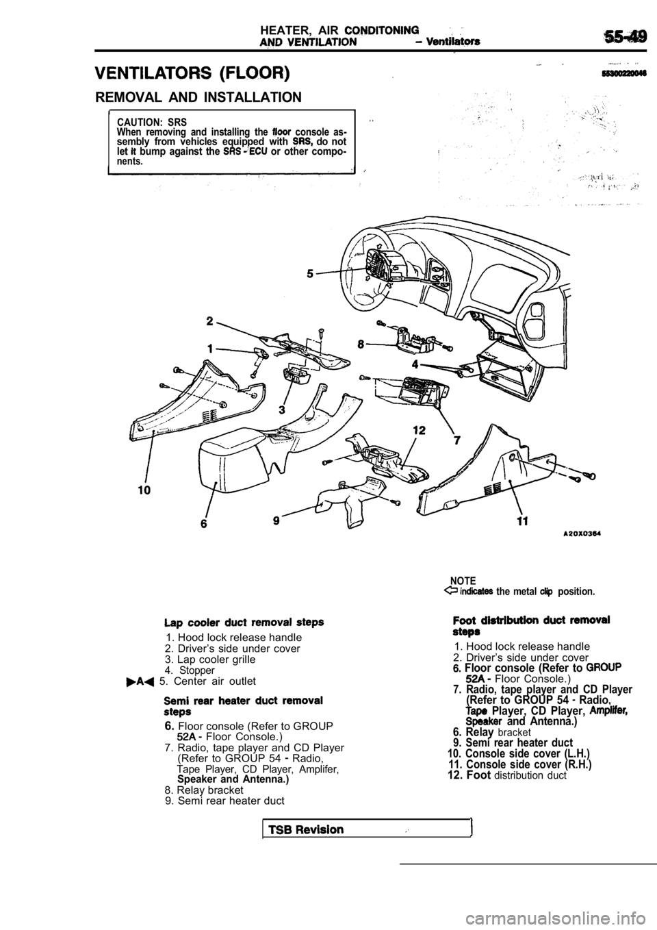
NOTE the metal position.
1. Hood lock release handle
2. Driver’s side under cover
3. Lap cooler grille
4. Stopper 5. Center air outlet
6. Floor console (Refer to GROUP Floor Console.)
7. Radio, tape player and CD Player (Refer to GROUP 54
Radio,Tape Player, CD Player, Amplifer,Speaker and Antenna.)
8. Relay bracket9. Semi rear heater duct
1. Hood lock release handle
2. Driver’s side under cover
Floor console (Refer to Floor Console.)7. Radio, tape player and CD Player(Refer to GROUP 54 Radio, Player, CD Player, and Antenna.)
6. Relay bracket9. Semi rear heater duct
10. Console side cover (L.H.) 11. Console side cover (R.H.)
12. Foot distribution duct
Page 2090 of 2103
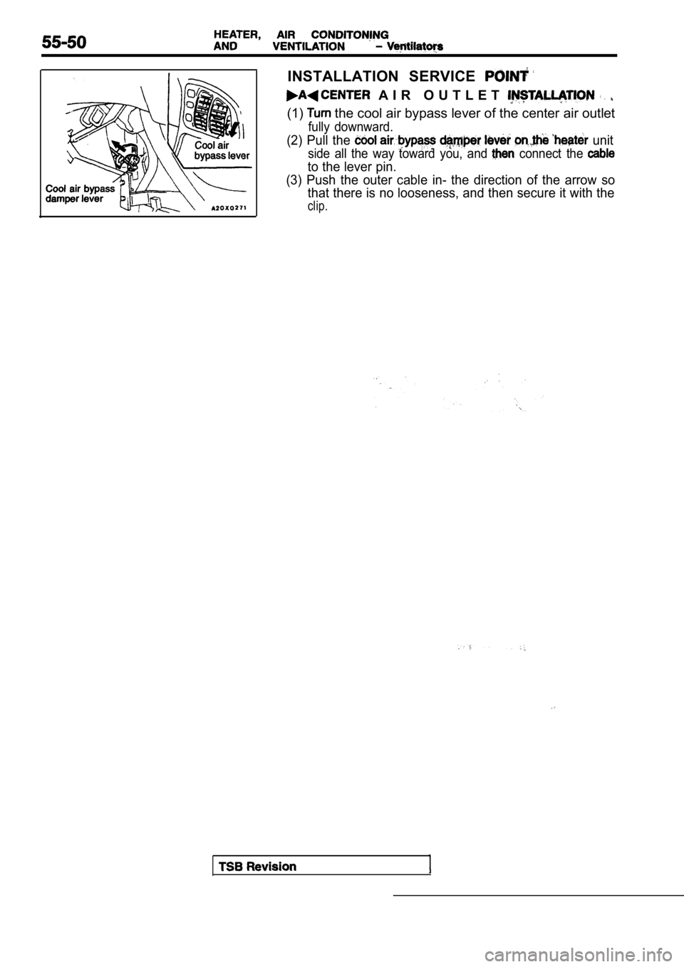
INSTALLATION SERVICE
A I R O U T L E T
(1) the cool air bypass lever of the center air outlet
fully downward.
(2) Pull the unit
side all the way toward you, and connect the
to the lever pin.
(3) Push the outer cable in- the direction of the a rrow so
that there is no looseness, and then secure it with the
clip.
Trending: gas mileage, brake, fuel pressure, brake rotor, towing, suspension, hood release
![MITSUBISHI SPYDER 1990 Service Repair Manual and Tension
Engine (Non-turbo)>
Bolt mm in.)]
Socket
Deep socket
(14 mm
in.)]
TSB
HUB REMOVAL
(1) Remove the clutch hub mounting bolt.
(2) Tighten a
mm in.) bolt into the ho MITSUBISHI SPYDER 1990 Service Repair Manual and Tension
Engine (Non-turbo)>
Bolt mm in.)]
Socket
Deep socket
(14 mm
in.)]
TSB
HUB REMOVAL
(1) Remove the clutch hub mounting bolt.
(2) Tighten a
mm in.) bolt into the ho](/img/19/57345/w960_57345-2080.png)


