MITSUBISHI SPYDER 1990 Service Repair Manual
Manufacturer: MITSUBISHI, Model Year: 1990, Model line: SPYDER, Model: MITSUBISHI SPYDER 1990Pages: 2103, PDF Size: 68.98 MB
Page 491 of 2103
ENGINE (NON-TURBO)> Troubleshooting
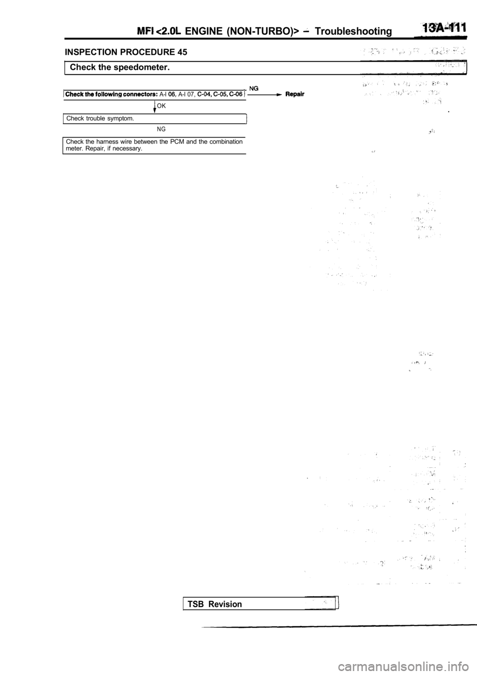
INSPECTION PROCEDURE 45Check the speedometer.
A-l A-l 07,
OK
Check trouble symptom.
NG
Check the harness wire between the PCM and the comb ination
meter. Repair, if necessary.
TSB Revision
.
Page 492 of 2103
ENGINE (NON-TURBO)> Troubleshooting
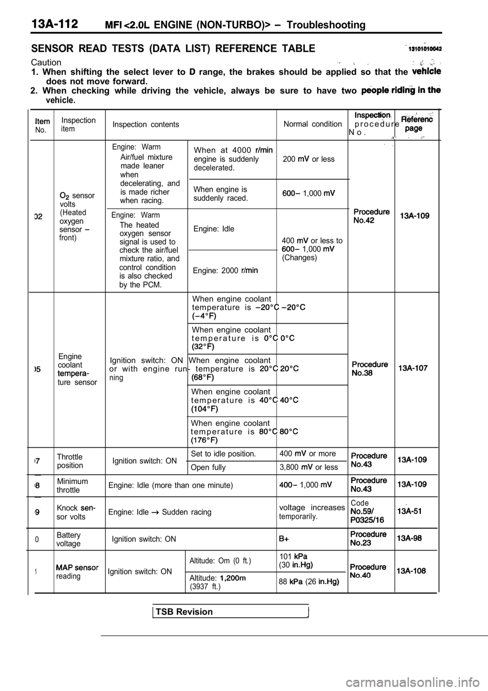
SENSOR READ TESTS (DATA LIST) REFERENCE TABLE
Caution
1. When shifting the select lever to range, the brakes should be applied so that the
does not move forward.
2. When checking while driving the vehicle, always be sure to have two
vehicle.
Inspection
No.itemInspection contents
Normal conditionp r o c e d u r e
N o .
Engine: WarmWhen at 4000 Air/fuel mixture
engine is suddenly 200 or less
made leaner
decelerated.when
decelerating, and
sensor is made richer
When engine is 1,000
voltswhen racing.
suddenly raced.
(Heated
oxygenEngine: Warm
The heatedsensoroxygen sensor Engine: Idlefront)signal is used to
400 or less to
check the air/fuel
1,000
mixture ratio, and (Changes)
control condition is also checked Engine: 2000
by the PCM.
When engine coolant
t e m p e r a t u r e i s
When engine coolant
t e m p e r a t u r e i s
Engine
coolantIgnition switch: ON When engine coolant
or with engine run- temperature is
ture sensorning
When engine coolant
t e m p e r a t u r e i s
When engine coolant
t e m p e r a t u r e i s
Throttle Set to idle position.
400 or more
position Ignition switch: ON
Open fully 3,800
or less
Minimum
throttle Engine: Idle (more than one minute) 1,000
KnockCode
sor voltsEngine: Idle Sudden racingvoltage increases
temporarily.
0Battery
voltage Ignition switch: ON
101
1
Altitude: Om (0 ft.)
reading
Ignition switch: ON (30Altitude:
(3937 ft.)88 (26
TSB Revision
Page 493 of 2103
ENGINE (NON-TURBO)>
I n s p e c t i o n
itemNo.Inspection contentsNormalconditionp r o c e d u r e
No.
12position
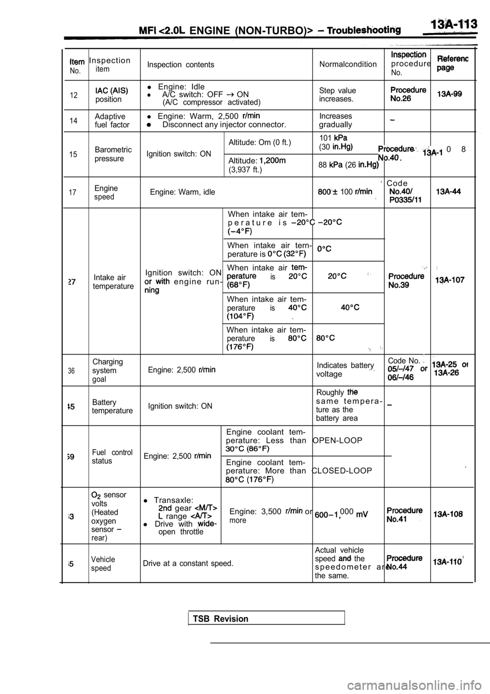
l Engine: IdlelA/C switch: OFF ON(A/C compressor activated) Step value
increases.
14
15
17
Adaptivel Engine: Warm, 2,500 Increases
fuel factor
Disconnect any injector connector. gradually
Altitude: Om (0 ft.) 101Barometric
Ignition switch: ON (30
pressureAltitude:
0 8
(3,937 ft.)
88 (26
C o d eEngine
speedEngine: Warm, idle 100
When intake air tem-
p e r a t u r e i s
When intake air tern-
perature is
When intake air
Intake airIgnition switch: ON
e n g i n e r u n - is
temperature
When intake air tem-
peratureis
36
Charging
system
goal
When intake air tem-
peratureis
Code No.
Engine: 2,500 Indicates battery
voltage
Roughly
Batterys a m e t e m p e r a -
temperature Ignition switch: ON
ture as the
battery area
Engine coolant tem-
perature: Less than OPEN-LOOP
Fuel control
status Engine: 2,500 Engine coolant tem-
.
perature: More than CLOSED-LOOP
sensor
volts
(Heated
oxygen
sensor
rear)
l Transaxle: gear Engine: 3,500 or 000 range l Drive with more
open throttle
Actual vehicle
Vehicle
speedDrive at a constant speed. speed the
s p e e d o m e t e r a r e .
the same.
TSB Revision
Page 494 of 2103
ENGINE (NON-TURBO)> Troubleshooting
,
p a g eNo.
66
39
71
inspection
No.
Procedure
Inspection
itemInspection contentsNormal condition
Engine: Warm
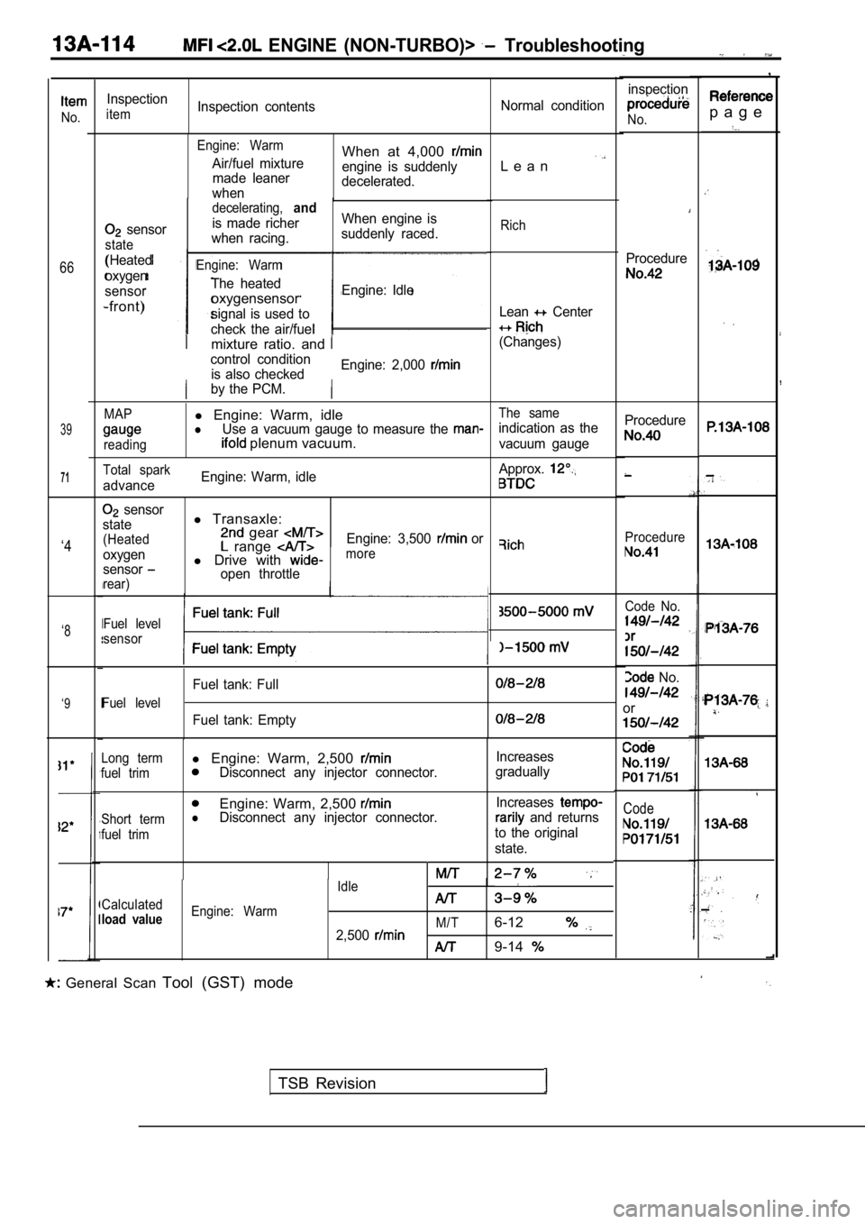
Air/fuel mixture
made leaner
whenWhen at 4,000
engine is suddenly
decelerated.L e a n
sensor
state
(Heated
oxygen
sensor
-front)
decelerating,and
is made richer When engine is
when racing. suddenly raced.
Engine: Warm
The heated
oxygensensorEngine: Idle
signal is used to
check the air/fuel
Rich
Lean Center
(Changes)mixture ratio. and
control condition is also checked Engine: 2,000
by the PCM.
MAPl
Engine: Warm, idleThe same
lUse a vacuum gauge to measure the indication as the
reading plenum vacuum.vacuum gauge Procedure
Procedure
Total spark
advance
Engine: Warm, idle
Approx.
sensor
state
(Heated
oxygen
sensor
rear)
l Transaxle: gear range l Drive with open throttle Engine: 3,500
or‘4more
Code No.
No.
or
Fuel level
sensor‘8
Fuel level
Fuel tank: Full
Fuel tank: Empty
‘9
Code
Long terml
Engine: Warm, 2,500 Increases
fuel trimDisconnect any injector connector. gradually
Engine: Warm, 2,500
Short termlDisconnect any injector connector. Increases and returns
fuel trimto the original
state.
Idle
Calculated
load valueEngine: Warm M/T
2,5006-12
9-14
General Scan Tool (GST) mode
TSB Revision
Page 495 of 2103
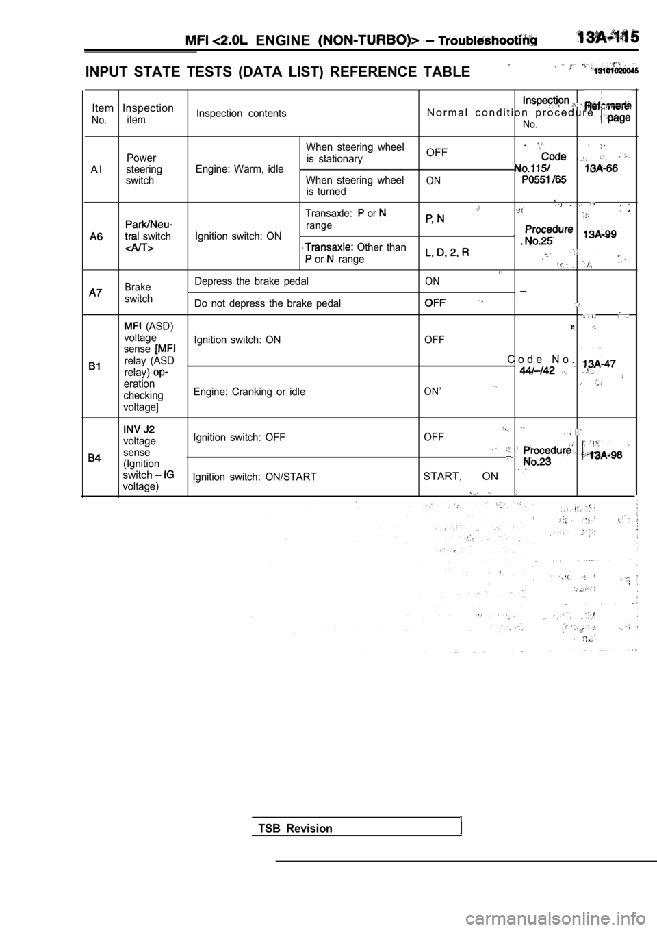
ENGINE
INPUT STATE TESTS (DATA LIST) REFERENCE TABLE
Item Inspection
No.itemInspection contentsN o r m a l c o n d i t i o n p r o c e d u r e
No.
A l
Power
steering
switch
switch
When steering wheel
is stationaryOFF
Engine: Warm, idle
When steering wheelONis turned,
Transaxle: or
rangeIgnition switch: ON
Other than
or range
BrakeDepress the brake pedalON
switch Do not depress the brake pedal.
(ASD)
voltage OFF
senseIgnition switch: ON
relay (ASD
C o d e N o .
relay)
erationON’checking Engine: Cranking or idle
voltage]
voltage Ignition switch: OFF
OFF
sense
(Ignition
switchSTART, ON voltage)Ignition switch: ON/START
TSB Revision
Page 496 of 2103
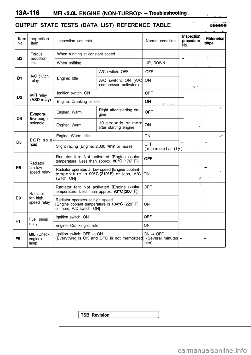
ENGINE (NON-TURBO)> , ,
OUTPUT STATE TESTS (DATA LIST) REFERENCE TABLE
Item Inspection
No. itemInspection contentsNormal condition ,
No.
TorqueWhen running at constant speed
reduction,
linkWhen shiftingUP, DOWN
A/C switch: OFFOFF
A/C clutch
relayEngine: IdleA/C switch: ON (A/C ON
compressor activated)
relayIgnition switch: ON
OFF
Engine: Cranking or idle
Engine: WarmRight after starting en-
gine
tive purge
solenoid
Engine: Warm1 0 s e c o n d s o r m o r e
after starting engine
Engine: Warm, idleON
E G R s o l e -OFFSlight racing (Engine: 2,000 or more)( m o m e n t a r i l y ). ..
Radiator fan: Not activated [Engine coolant
Radiator temperature: Less than approx. (176” F)]
fan lowRadiator operates at low speed [Engine coolantspeed relaye m p e r a t u r e i s or less, A/C ON
switch: ON]
Radiator fan: Not activated [Engine OFF
Radiatortemperature: Less than approx.
fan high
speed relay Radiator operates at high speed.
ngine coolant temperature is (220” F)ON
or more, A/C switch: ON]
Fuel pumpIgnition switch: ON
OFF
relayEngine: Cranking or idleON
(CheckIgnition switch: OFF ON
ON OFF
engine)(Everything is OK and DTC is not memorized) (Severa l minutes
lamp later)
TSB Revision
Page 497 of 2103
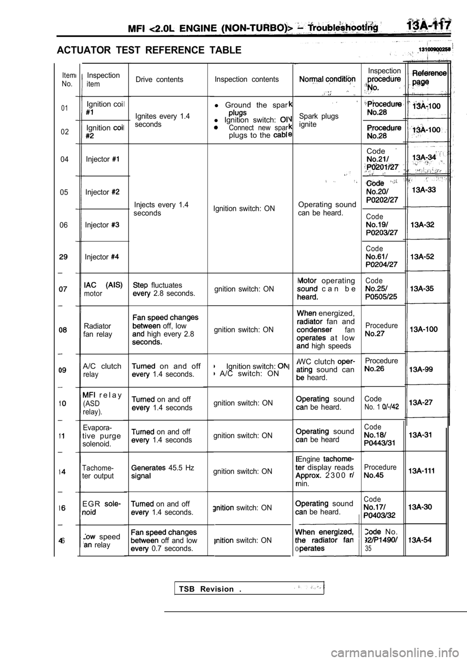
ACTUATOR TEST REFERENCE TABLE
Drive contentsInspection contents
l
Ground the spar
l Ignition switch: Connect new sparplugs to the
Spark plugs
ignite
Ignition switch: ONOperating sound
can be heard.
gnition switch: ON
operating
c a n b e
gnition switch: ON
energized,
fan and
fan
a t l o w
high speeds
Ignition switch: A/C switch: ON WC clutch sound can
heard.
gnition switch: ON
sound
be heard.
gnition switch: ON
sound
be heard
gnition switch: ON Engine
display reads
2 3 0 0
nin.
switch: ON
switch: ON
I
I
0
sound
be heard.
Item
No.
01
02
04
05
06
6
Inspection
Code
,
Code
Code
Code
Procedure
Procedure
Code
No. 1
Code
Procedure
Code
No.
35
Inspection
item
Ignition coi
Ignition
Injector
Injector
Injector
Injector
motor
Radiator
fan relay
A/C clutch
relay
r e l a y
(ASD
relay).
Evapora-
tive purge
solenoid.
Tachome-
ter output
E G R
speed
relay Ignites every 1.4
seconds
I
I
Injects every 1.4
seconds
fluctuates
2.8 seconds.
off, low
high every 2.8
on and off
1.4 seconds.
on and off
1.4 seconds
on and off
1.4 seconds
45.5 Hz
on and off
1.4 seconds.
off and low
0.7 seconds.
TSB Revision .
Page 498 of 2103
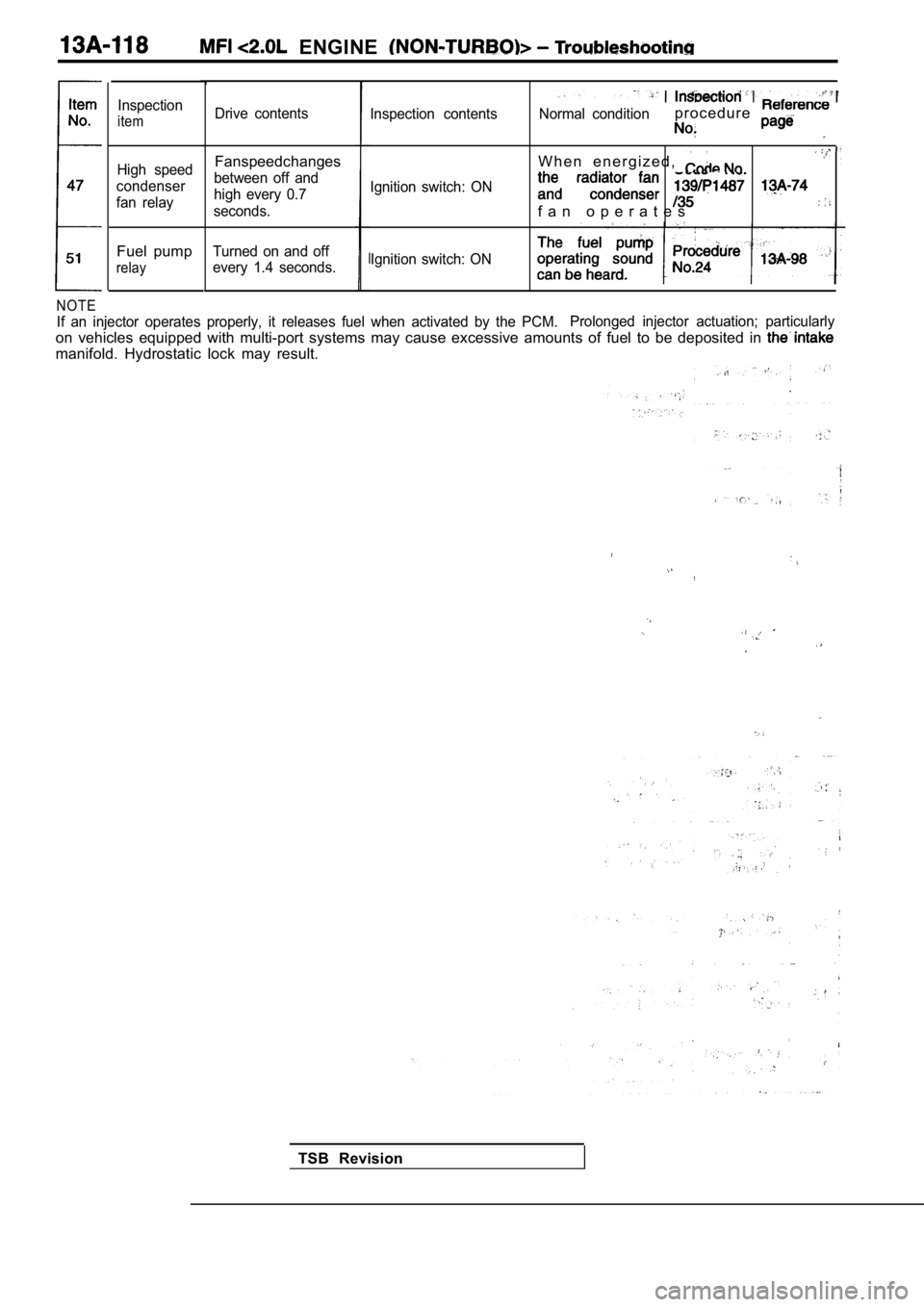
ENGINE
NOTE
If an injector operates properly, it releases fuel when activated by the PCM.Prolonged injector actuation; particularly
on vehicles equipped with multi-port systems may ca
use excessive amounts of fuel to be deposited in
manifold. Hydrostatic lock may result.
Inspection
item
High speed
condenser
fan relay
Fuel pump
relay
Drive contents
Fanspeedchanges
between off and
high every 0.7
seconds.
Turned on and off
every 1.4 seconds. Inspection contents
Ignition switch: ON
Ignition switch: ON Normal condition
p r o c e d u r e
W h e n e n e r g i z e d ,
f a n o p e r a t e s
TSB Revision
Page 499 of 2103
ENGINE (NON-TURBO)>
ON-VEHICLE SERVICE
THROTTLE BODY MINIMUM AIR FLOW
CHECK
1.Start the engine and warm it up until the engine co olant
is heated to
or higher and then stop the
engine.
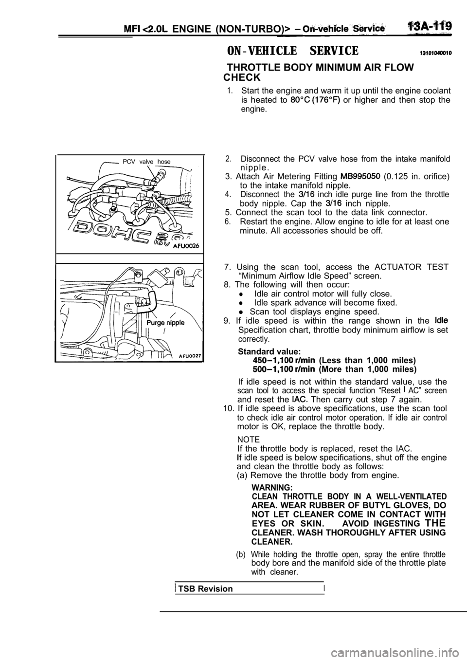
PCV valve hose2.Disconnect the PCV valve hose from the intake manif old
n i p p l e .
3. Attach Air Metering Fitting
(0.125 in. orifice)
to the intake manifold nipple.
4.Disconnect the inch idle purge line from the throttle
body nipple. Cap the inch nipple.
5. Connect the scan tool to the data link connector .
6.Restart the engine. Allow engine to idle for at least one
minute. All accessories should be off.
7. Using the scan tool, access the ACTUATOR TEST “Minimum Airflow Idle Speed” screen.
8. The following will then occur:
lIdle air control motor will fully close.
lIdle spark advance will become fixed.
l Scan tool displays engine speed.
9. If idle speed is within the range shown in the
Specification chart, throttle body minimum airflow is set
correctly.
Standard value:
(Less than 1,000 miles)
(More than 1,000 miles)
If idle speed is not within the standard value, use the
scan tool to access the special function “Reset AC” screen
and reset the Then carry out step 7 again.
10. If idle speed is above specifications, use the scan tool
to check idle air control motor operation. If idle air control
motor is OK, replace the throttle body.
NOTE
If the throttle body is replaced, reset the IAC.
idle speed is below specifications, shut off the e ngine
and clean the throttle body as follows: (a) Remove the throttle body from engine.
WARNING:
CLEAN THROTTLE BODY IN A WELL-VENTILATED
AREA. WEAR RUBBER OF BUTYL GLOVES, DO
NOT LET CLEANER COME IN CONTACT WITH
EYES OR SKIN. AVOID INGESTING THE
CLEANER. WASH THOROUGHLY AFTER USING
CLEANER.
(b) While holding the throttle open, spray the entir e throttle
body bore and the manifold side of the throttle plate
with cleaner.
TSB RevisionI
Page 500 of 2103
( N O N - T U R B O ) > . .
(c) Using a soft scuff pad, clean the top and bottom
of throttle body bore and the edges and manifold
side of, ‘the throttle blade. The edges of the thro ttle
blade and portions of the throttle bore that are cl osest
to the throttle blade when closed, must be free of
deposits.
(d) Use compressed air to dry the throttle body.
(e) Inspect throttle body for foreign material.
(f) Install throttle body on manifold.
(g) Repeat steps 1through 14. If the minimum air flow
is still not within specifications, the problem is not
caused by the throttle body.
11. Shut off engine.
12. Remove Air Metering Fitting from, the intake
manifold PCV nipple. Reinstall the
13. Uncap the throttle body idle and connect
the idle purge line.
14. Remove the scan tool. . .
. ,
TSB Revision