MITSUBISHI SPYDER 1990 Service Repair Manual
SPYDER 1990
MITSUBISHI
MITSUBISHI
https://www.carmanualsonline.info/img/19/57345/w960_57345-0.png
MITSUBISHI SPYDER 1990 Service Repair Manual
Trending: checking oil, driver seat adjustment, trunk release, run flat, air condition, hood release, transmission oil
Page 501 of 2103
E N G I N E ,
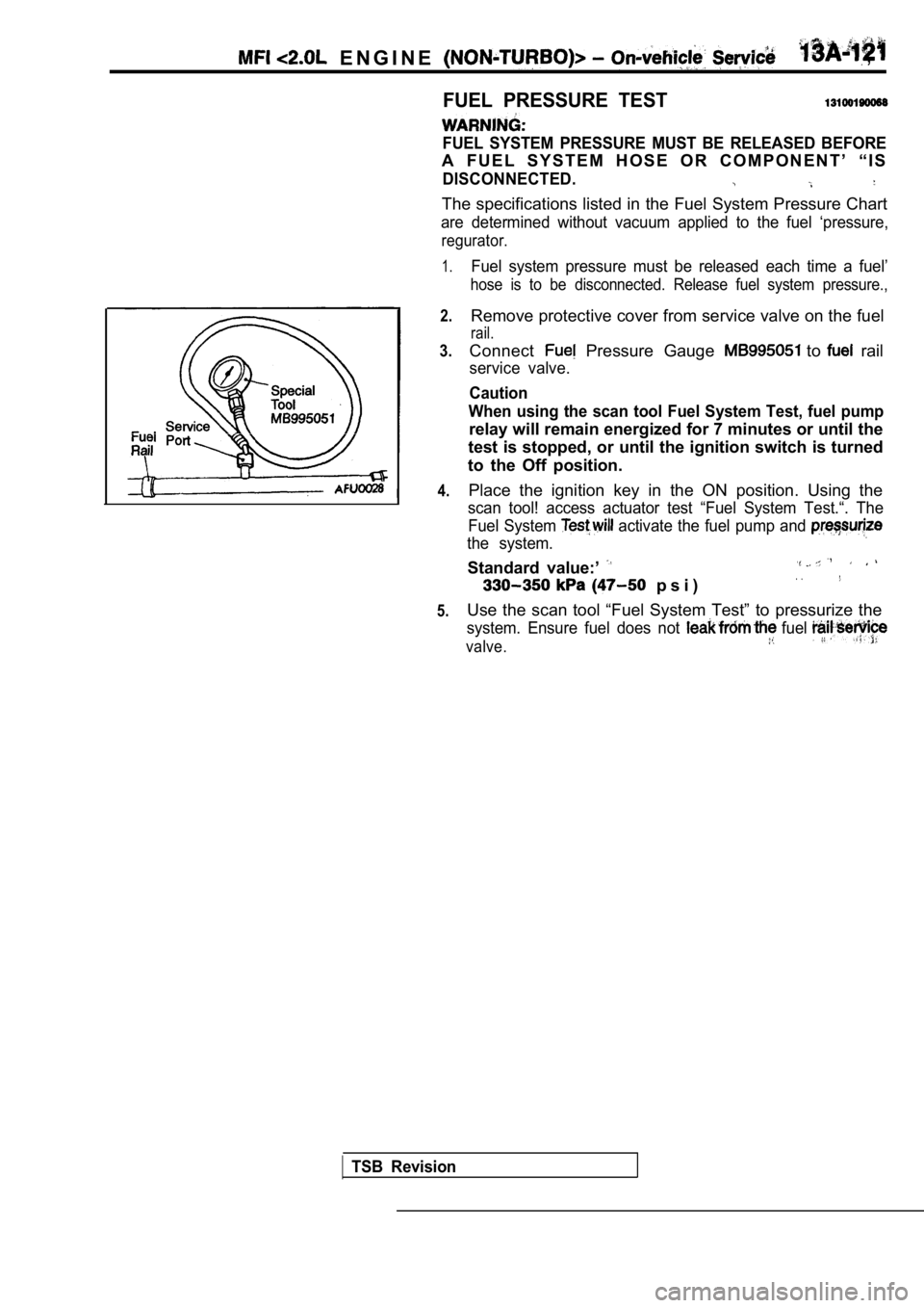
FUEL PRESSURE TEST
FUEL SYSTEM PRESSURE MUST BE RELEASED BEFORE
A F U E L S Y S T E M H O S E O R C O M P O N E N T ŌĆÖ ŌĆ£ I S
DISCONNECTED.
The specifications listed in the Fuel System Pressure Chart
are determined without vacuum applied to the fuel ŌĆś pressure,
regurator.
1.
2.
3.
4.
5.
Fuel system pressure must be released each time a f uelŌĆÖ
hose is to be disconnected. Release fuel system pre ssure.,
Remove protective cover from service valve on the fuel
rail.
Connect Pressure Gauge to rail
service valve.
Caution
When using the scan tool Fuel System Test, fuel pum p
relay will remain energized for 7 minutes or until the
test is stopped, or until the ignition switch is tu rned
to the Off position.
Place the ignition key in the ON position. Using th e
scan tool! access actuator test ŌĆ£Fuel System Test.ŌĆ£. The
Fuel System
activate the fuel pump and
the system.
Standard value:ŌĆÖ
p s i )
Use the scan tool ŌĆ£Fuel System TestŌĆØ to pressurize the
system. Ensure fuel does not fuel
valve.
TSB Revision
Page 502 of 2103
ENGINE
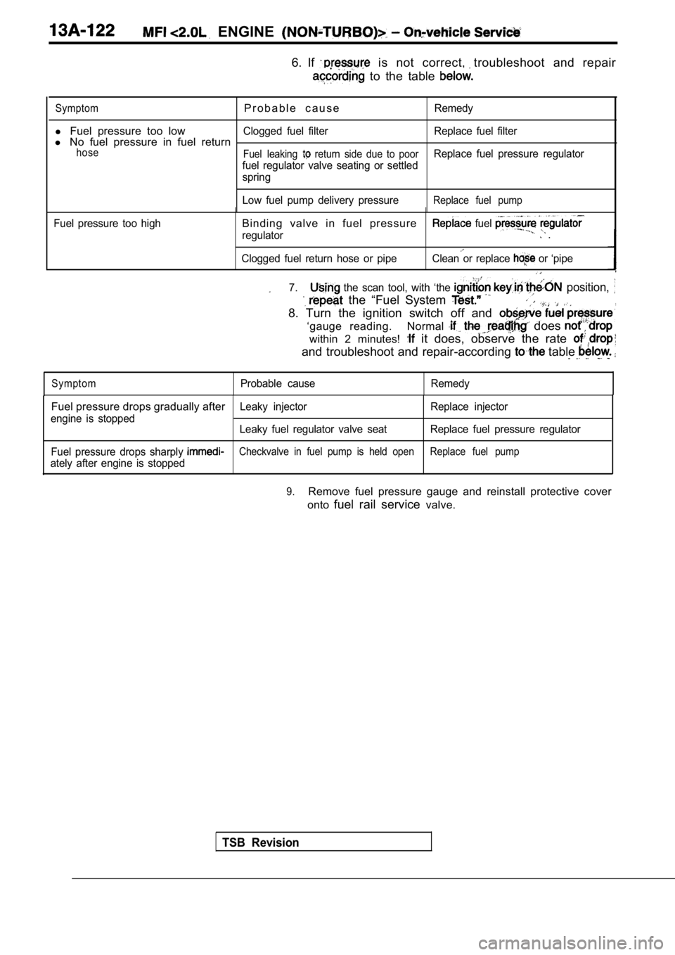
6. If is not correct, troubleshoot and repair
to the table
SymptomP r o b a b l e c a u s eRemedy
l Fuel pressure too lowClogged fuel filter Replace fuel filterl No fuel pressure in fuel returnhose
Fuel leaking return side due to poorReplace fuel pressure regulator
fuel regulator valve seating or settled
spring
Low fuel pump delivery pressure
Replace fuel pump
Fuel pressure too highBinding valve in fuel pressure
regulator
fuel .
Clogged fuel return hose or pipeClean or replace or ŌĆśpipe
7. the scan tool, with ŌĆśthe position,
the ŌĆ£Fuel System ,
8. Turn the ignition switch off and
ŌĆśgauge reading. Normal does
within 2 minutes! it does, observe the rate
and troubleshoot and repair-according table
SymptomProbable cause Remedy
Fuel pressure drops gradually afterLeaky injector Replace injector
engine is stopped Leaky fuel regulator valve seat Replace fuel pressur e regulator
Fuel pressure drops sharply
Checkvalve in fuel pump is held open Replace fuel pu mp
ately after engine is stopped
TSB Revision
9.Remove fuel pressure gauge and reinstall protective cover
onto fuel rail service valve.
Page 503 of 2103
ENGINE (NON-TURBO)> On-vehicle
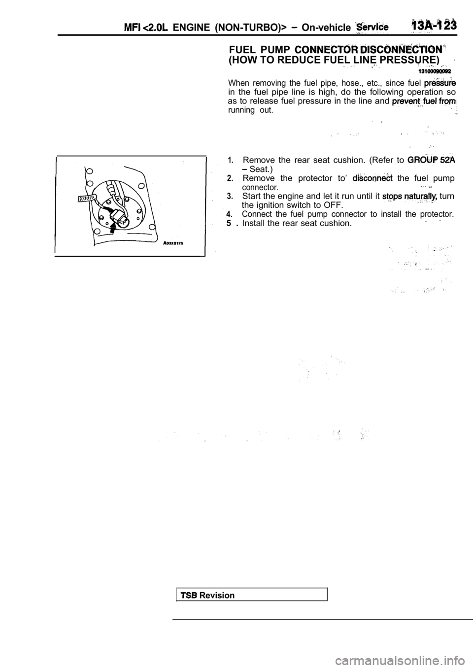
FUEL PUMP
(HOW TO REDUCE FUEL LINE PRESSURE)
When removing the fuel pipe, hose., etc., since fuel
in the fuel pipe line is high, do the following operation so
as to release fuel pressure in the line and
running out.
.
1.
2.
3.
4.
5 . Remove the rear seat cushion. (Refer to
Seat.)
Remove the protector toŌĆÖ
the fuel pump
connector.
Start the engine and let it run until it turn
the ignition switch to OFF.
Connect the fuel pump connector to install the prot ector.
Install the rear seat cushion..
Revision
Page 504 of 2103
ENGINE (NON-TURBO)> .
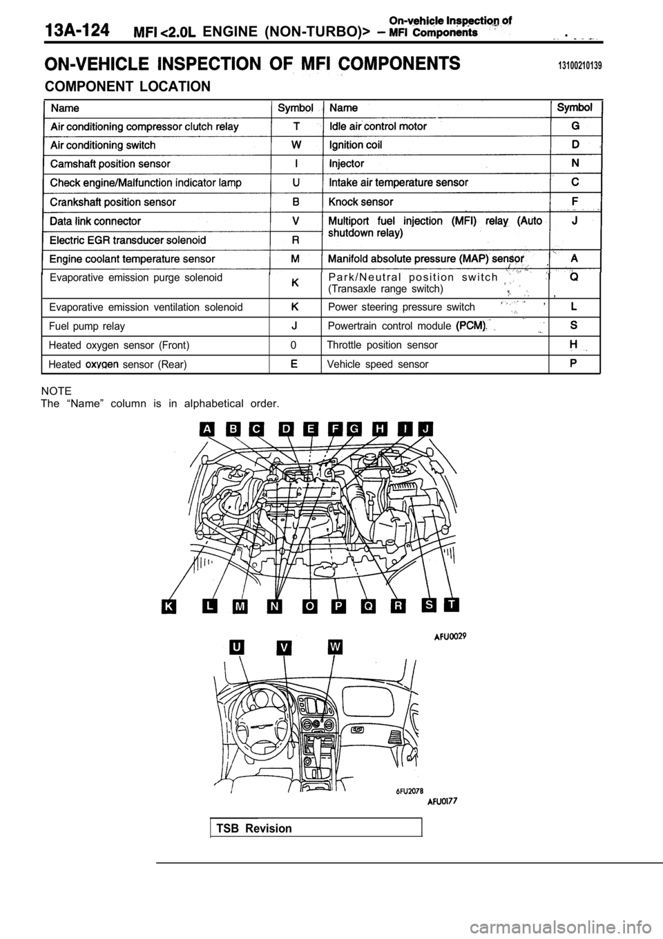
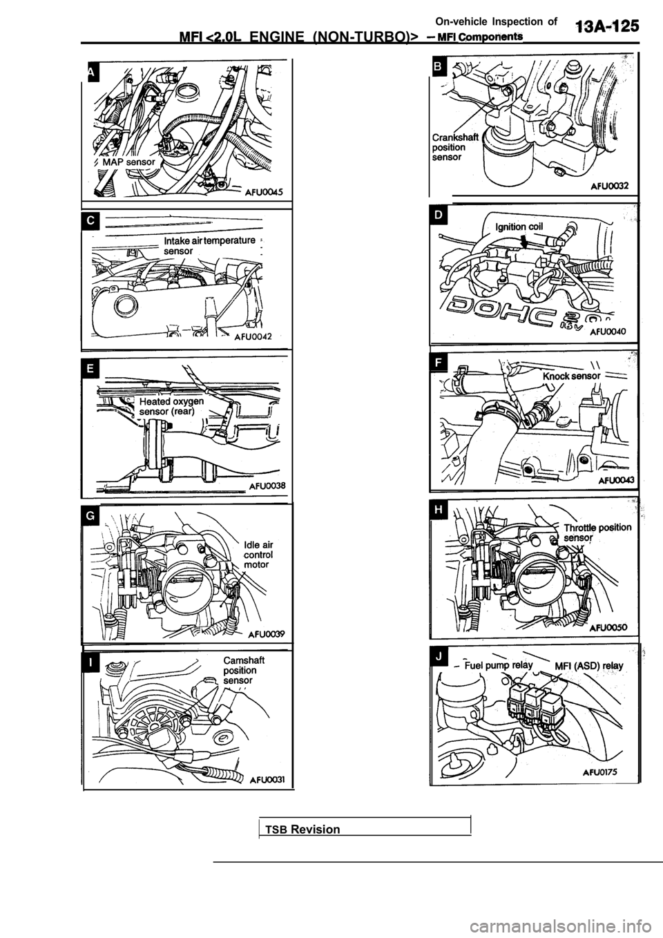
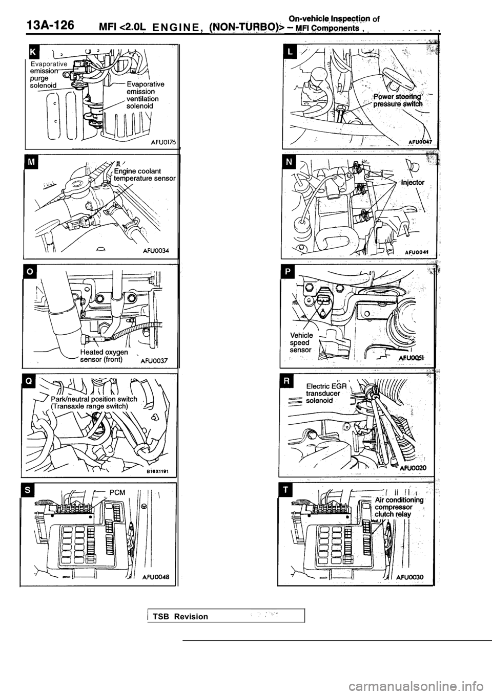
13100210139
COMPONENT LOCATION
Evaporative emission purge solenoid
Evaporative emission ventilation solenoid
Fuel pump relay
Heated oxygen sensor (Front)
Heated
sensor (Rear)
P a r k / N e u t r a l p o s i t i o n s w i t c h
(Transaxle range switch) ,
Power steering pressure switch ,
Powertrain control module
0Throttle position sensor
Vehicle speed sensor
NOTE
The ŌĆ£NameŌĆØ column is in alphabetical order.
TSB Revision
Page 505 of 2103
On-vehicle Inspection of
ENGINE (NON-TURBO)>
TSBRevision
Page 506 of 2103
of
E N G I N E , , ,
Evaporative
TSB Revision
Page 507 of 2103
Page 508 of 2103
28 of
( N O N - T U R B O ) >
Bottom view
of relay
I
Intake air temperature
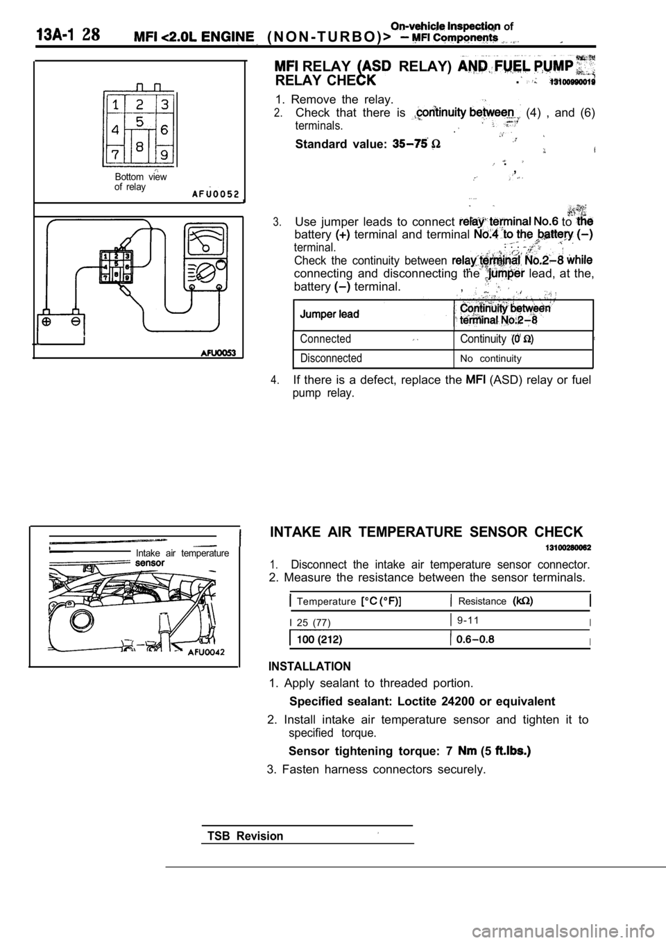
RELAY RELAY)
RELAY CHE.
1. Remove the relay.
2.Check that there is (4) , and (6)
terminals..
Standard value:
.,
3.Use jumper leads to connect to
battery terminal and terminal
terminal.. . .
Check the continuity between
connecting and disconnecting the lead, at the,
battery
terminal. ,
Connected
DisconnectedContinuity
No continuity
4.If there is a defect, replace the (ASD) relay or fuel
pump relay.
INTAKE AIR TEMPERATURE SENSOR CHECK
1.Disconnect the intake air temperature sensor connec tor.
2. Measure the resistance between the sensor terminals.
Temperature Resistance
I 25 (77) 9 - 1 1I
I
INSTALLATION
1. Apply sealant to threaded portion.
Specified sealant: Loctite 24200 or equivalent
2. Install intake air temperature sensor and tighte n it to
specified torque.
Sensor tightening torque: 7 (5
3. Fasten harness connectors securely.
TSB Revision
Page 509 of 2103
On-vehicle Inspection of
ENGINE
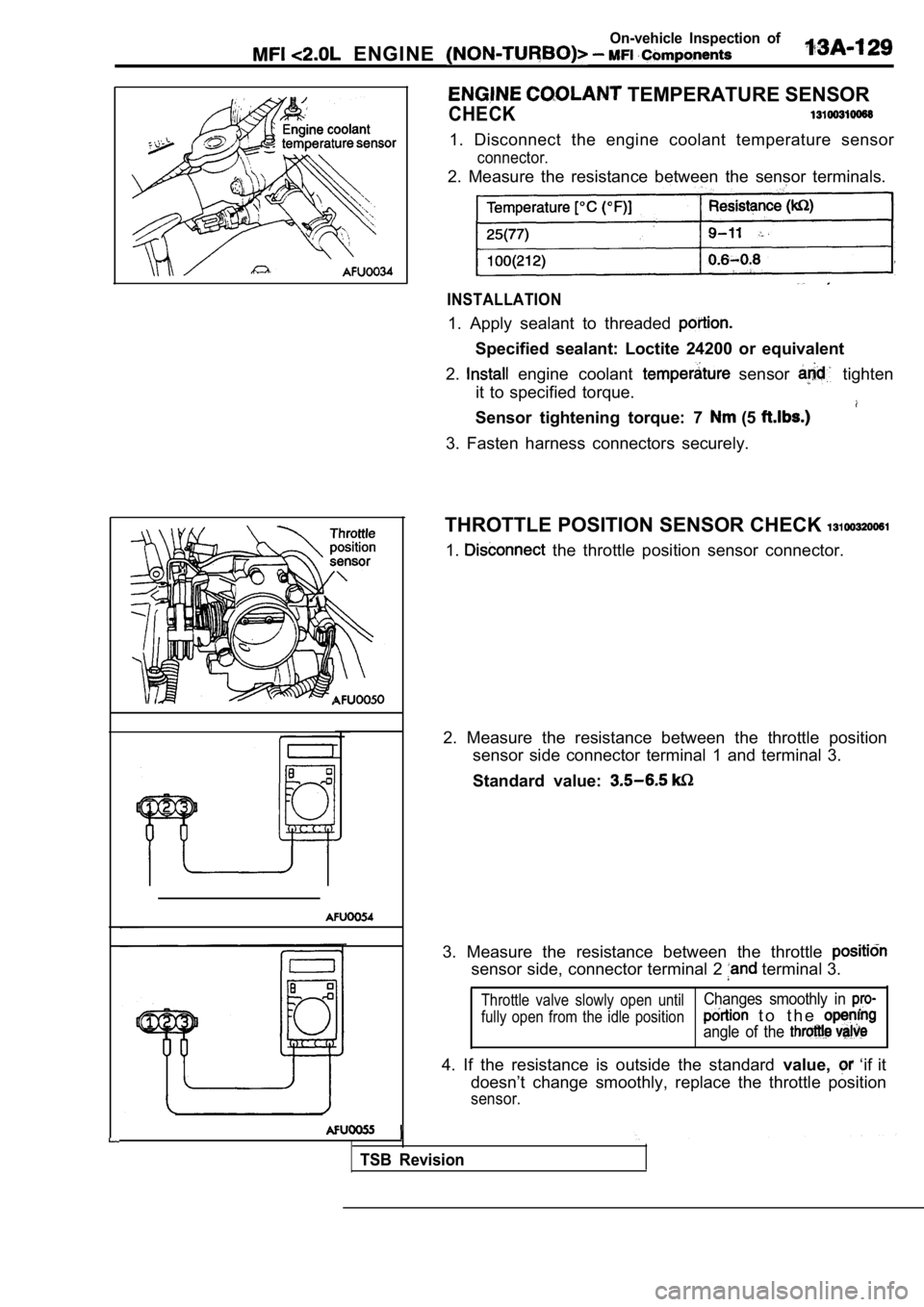
TEMPERATURE SENSOR
CHECK
1. Disconnect the engine coolant temperature sensor
connector.
2. Measure the resistance between the sensor terminals.
INSTALLATION
1. Apply sealant to threaded
Specified sealant: Loctite 24200 or equivalent
2.
engine coolant sensor tighten
it to specified torque.
Sensor tightening torque: 7 (5
3. Fasten harness connectors securely.
THROTTLE POSITION SENSOR CHECK
1. the throttle position sensor connector.
2. Measure the resistance between the throttle posi tion
sensor side connector terminal 1 and terminal 3.
Standard value:
3. Measure the resistance between the throttle
sensor side, connector terminal 2 terminal 3.
Throttle valve slowly open until
fully open from the idle positionChanges smoothly in
t o t h e
angle of the
4. If the resistance is outside the standard value, ŌĆśif it
doesnŌĆÖt change smoothly, replace the throttle posit ion
sensor.
TSB Revision
Page 510 of 2103
On-vehicle of
ENGINE ( N O N - T U R B O ) >
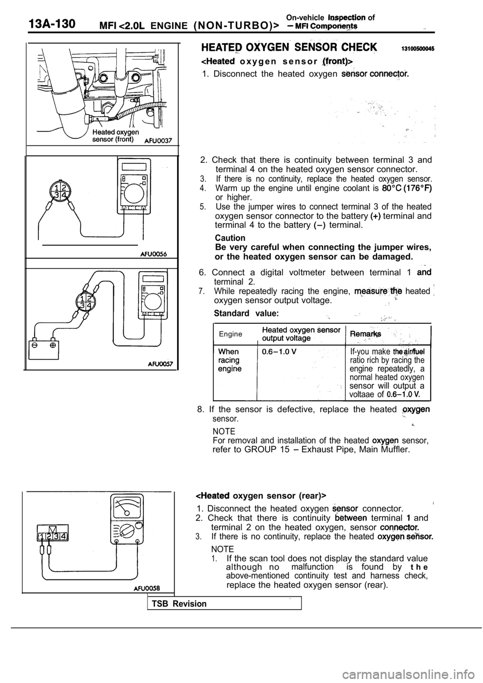
o x y g e n s e n s o r
1. Disconnect the heated oxygen
2. Check that there is continuity between terminal 3 and
terminal 4 on the heated oxygen sensor connector.
3.If there is no continuity, replace the heated oxyge n sensor.
4.Warm up the engine until engine coolant is
or higher.
5.Use the jumper wires to connect terminal 3 of the h eated
oxygen sensor connector to the battery terminal and
terminal 4 to the battery
terminal.
Caution
Be very careful when connecting the jumper wires,
or the heated oxygen sensor can be damaged.
6. Connect a digital voltmeter between terminal 1
terminal 2.
7.While repeatedly racing the engine, heated
oxygen sensor output voltage.
Standard value:
Engine
TSB Revision
If-you make
ratio rich by racing the
engine repeatedly, a
normal heated oxygen
sensor will output a
voltaae of
8. If the sensor is defective, replace the heated
sensor.
NOTE
For removal and installation of the heated sensor,
refer to GROUP 15 Exhaust Pipe, Main Muffler.
oxygen sensor (rear)>
1. Disconnect the heated oxygen
connector.
2. Check that there is continuity terminal and
terminal 2 on the heated oxygen, sensor
3.If there is no continuity, replace the heated
NOTE
1.If the scan tool does not display the standard valu e
although no
malfunctionis found by t h e
above-mentioned continuity test and harness check,
replace the heated oxygen sensor (rear).
Trending: fuel tank capacity, battery, differential, transmission fluid, brake pads replacement, catalytic converter, oil change


