MITSUBISHI SPYDER 1990 Service Repair Manual
SPYDER 1990
MITSUBISHI
MITSUBISHI
https://www.carmanualsonline.info/img/19/57345/w960_57345-0.png
MITSUBISHI SPYDER 1990 Service Repair Manual
Trending: stop start, steering wheel adjustment, open hood, clock, reset, turn signal, OBD port
Page 921 of 2103
MANUAL TRANSAXLE OVERHAUL
Transaxle
IDLER GEAR SHAFT BOLT
INSTALLATION
(1)Center the shaft with a Phillips screwdriver [shaft diameter
8 mm in.)] or the like.
(2) Tighten the reverse idler gear shaft bolt to th e specified
torque.
LOCK NUTS FOR INPUT SHAFT
INTERMEDIATE GEAR INSTALLATION,
(1) Install the special tool onto the input shaft.
(2) Screw a bolt [IO mm in.)] into the hole around clutch
housing and attach a handle to the
(3)Shift the transaxle in reverse using control lever and
(4) the lock nut to the specified torque, using
the bolt attached in the above step as a spinner ha ndle
stopper.
(5) Stake the lock nut.
PIN FOR SHIFT FORK
INSTALLATION
TSB Revision
Page 922 of 2103
MANUAL TRANSAXLE OVERHAUL
Transaxle .
22210033
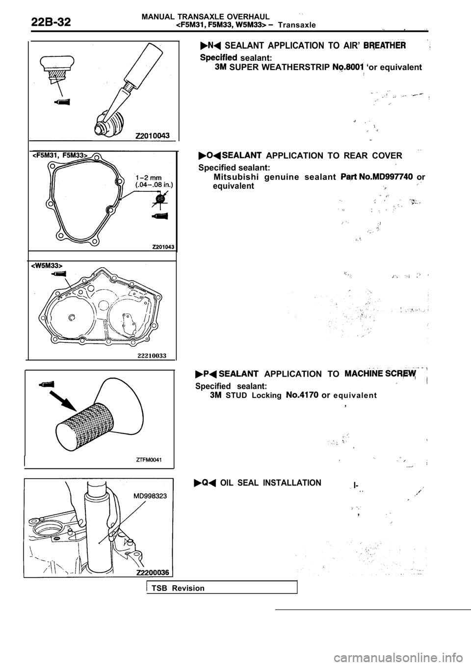
SEALANT APPLICATION TO AIR’
sealant:
SUPER WEATHERSTRIP ‘or equivalent
APPLICATION TO REAR COVER
Specified sealant:
Mitsubishi genuine sealant or
equivalent
APPLICATION TO
Specified sealant:
STUD Locking or e q u i v a l e n t
,
OIL SEAL INSTALLATION I-. .
,
TSB Revision
Page 923 of 2103
MANUAL OVERHAUL
Transaxle
Oil seal
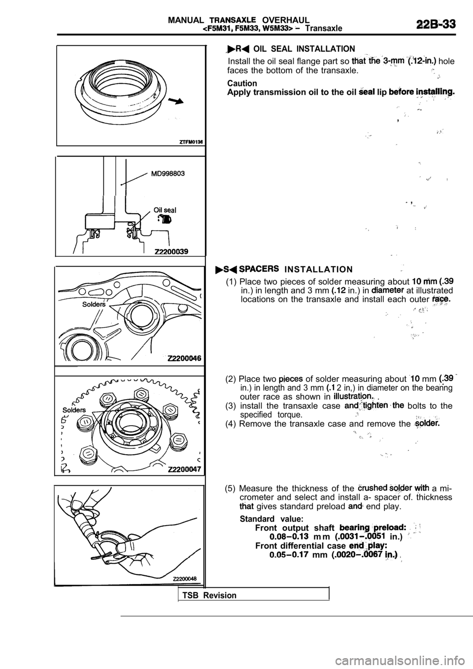
OIL SEAL INSTALLATION
Install the oil seal flange part so hole
faces the bottom of the transaxle.
Caution
Apply transmission oil to the oil lip
,
,
,
I N S T A L L A T I O N
(1) Place two pieces of solder measuring about
in.) in length and 3 mm in.) in at illustrated
locations on the transaxle and install each outer
(2) Place two of solder measuring about mm
in.) in length and 3 mm 2 in,) in diameter on the beanng
outer race as shown in .
(3) install the transaxle case
bolts to the
specified torque.
(4) Remove the transaxle case and remove the
(5) Measure the thickness of the a mi-
crometer and select and install a- spacer of. thick ness
gives standard preload end play.
Standard value:
Front output shaft
m m in.)
Front differential case
mm
TSB Revision
Page 924 of 2103
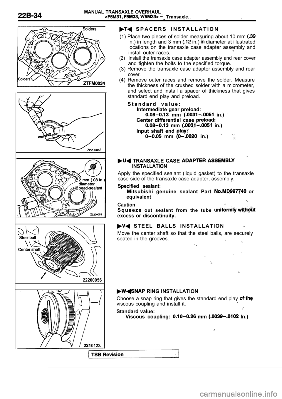
MANUAL TRANSAXLE OVERHAUL
Transaxle.,
22200056
0123
S P A C E R S I N S T A L L A T I O N
(1) Place two pieces of solder measuring about 10 m m
in.) in length and 3 mm in.) diameter at illustrated
locations on the transaxle case adapter assembly an d
install outer races.
(2)Install the transaxle case adapter assembly and rea r cover
and tighten the bolts to the specified torque.
(3) Remove the transaxle case adapter assembly and rear
cover.
(4) Remove outer races and remove the solder. Measu re
the thickness of the crushed solder with a micromet er,
and select and install a spacer of thickness that g ives
standard end play and preload.
S t a n d a r d v a l u e : Intermediate gear preload:
mm in.)
Center differential case
mm in.)
Input shaft end
mm in.)
TRANSAXLE CASE
INSTALLATION
Apply the specified sealant (liquid gasket) to the transaxle
case side of the transaxle case adapter, assembly.
Specified sealant:
Mitsubishi genuine sealant Part or
equivalent
Caution
S q u e e z e o u t s e a l a n t f r o m t h e t u b e
excess or discontinuity.
S T E E L B A L L S I N S T A L L A T I O N--
Move the center shaft so that the steel balls, are securely
seated in the grooves.
RING INSTALLATION
Choose a snap ring that gives the standard end play
viscous coupling and install it..
Standard value:
Viscous coupling: mm In.)
Page 925 of 2103
MANUAL TRANSAXLE OVERHAUL
Transaxle
0
00
0
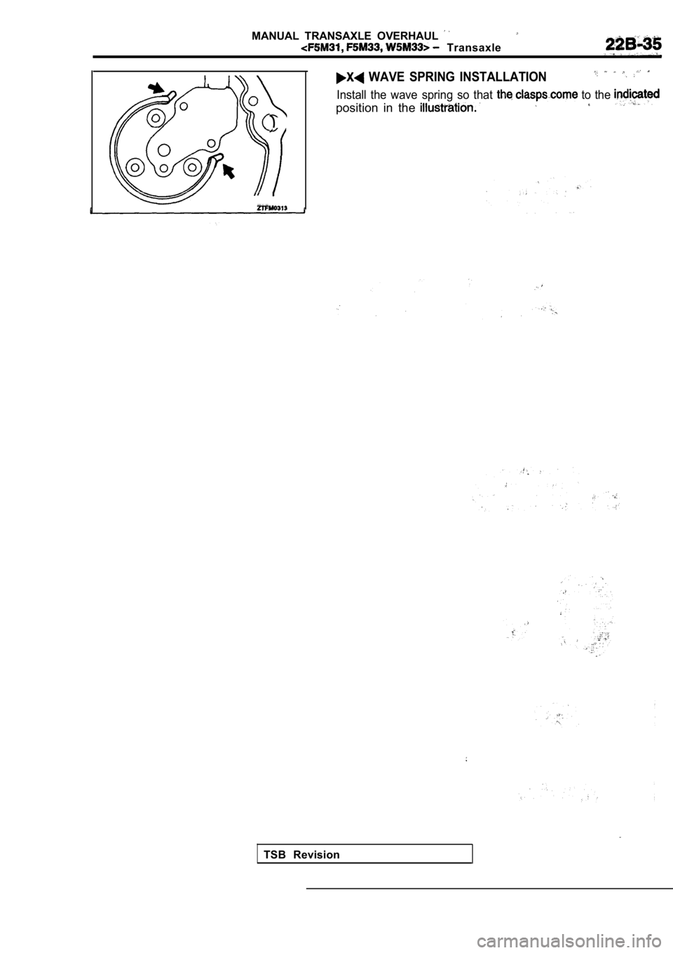
WAVE SPRING INSTALLATION
Install the wave spring so that to the
position in the
TSB Revision
Page 926 of 2103
MANUAL TRANSAXLE OVERHAUL
Synchronizer
SYNCHRONIZER
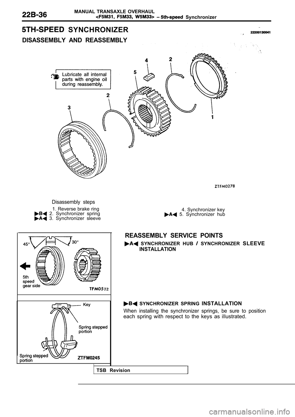
DISASSEMBLY AND REASSEMBLY
Disassembly steps
1. Reverse brake ring 2. Synchronizer spring 3. Synchronizer sleeve
72
4. Synchronizer key 5. Synchronizer hub
REASSEMBLY SERVICE POINTS
SYNCHRONIZER HUB SYNCHRONIZER SLEEVE
INSTALLATION
SYNCHRONIZER SPRING INSTALLATION
When installing the synchronizer springs, be sure t o position
each spring with respect to the keys as illustrated.
TSB Revision
Page 927 of 2103
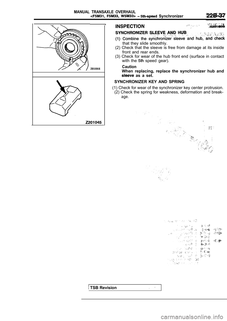
MANUAL TRANSAXLE OVERHAUL
Synchronizer
201044
that they slide smoothly.
(2) Check that the sleeve is free from damage at it s inside
front and rear ends.
(3) Check for wear of the hub front end (surface in contact
with the
speed gear).
Caution
When replacing, replace the synchronizer hub and
as a set.
SYNCHRONIZER KEY AND SPRING
(1) Check for wear of the synchronizer key center p rotrusion.
(2) Check the spring for weakness, deformation and break-
age.
TSB Revision
Page 928 of 2103
MANUAL TRANSAXLE OVERHAUL
Input Shaft
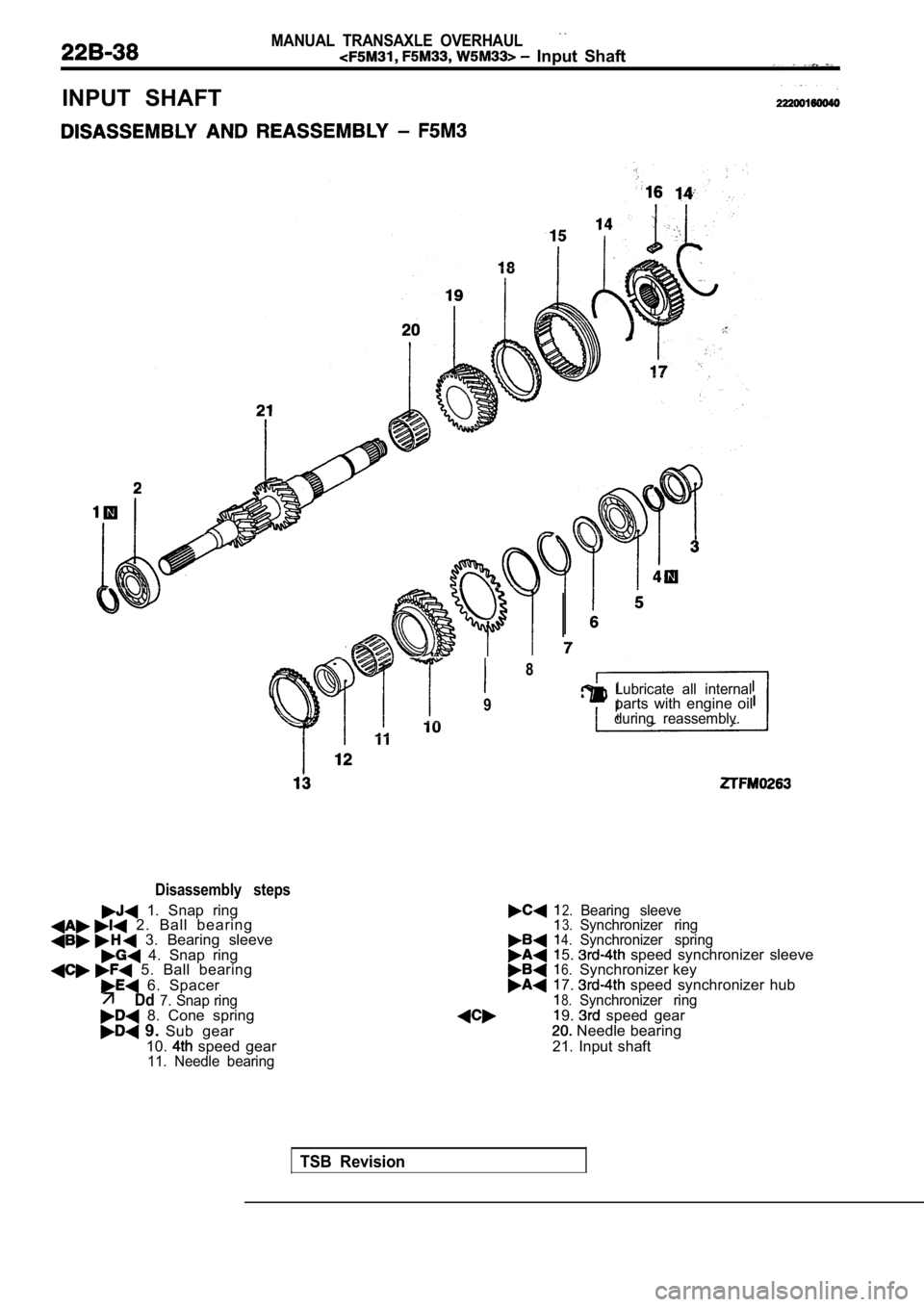
INPUT SHAFT
Disassembly steps
1. Snap ring 2. Ball bearing 3. Bearing sleeve 4. Snap ring 5. Ball bearing
6. Spacer
Page 929 of 2103
MANUAL TRANSAXLE OVERHAUL
Input Shaft
4
q 5
6
11
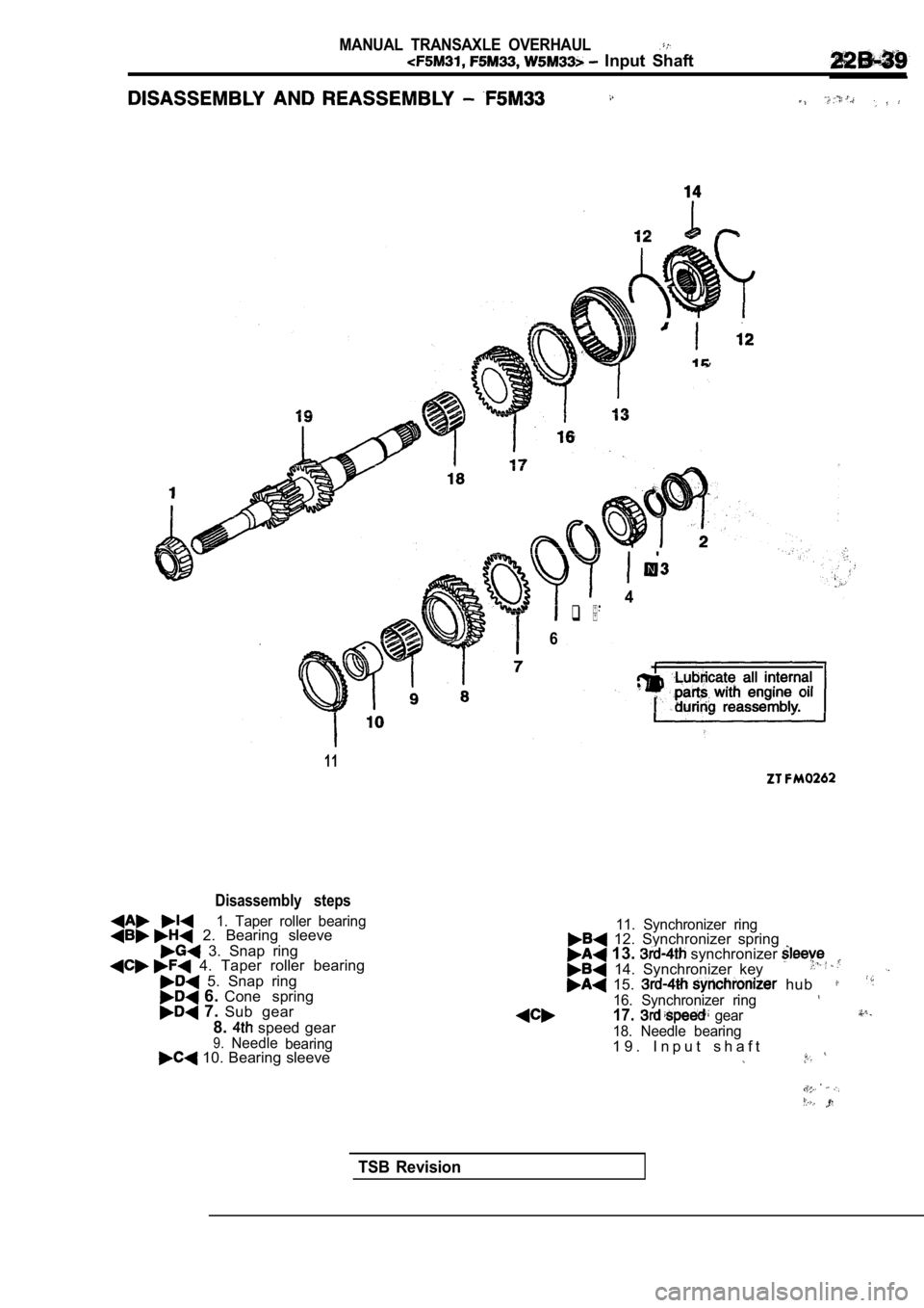
Disassembly steps
1. Taper roller bearing 2. Bearing sleeve
3. Snap ring 4. Taper roller bearing
5. Snap ring 6. Cone spring 7. Sub gear
8.
speed gear9.Needle bearing 10. Bearing sleeve
11. Synchronizer ring 12. Synchronizer spring 13. synchronizer 14. Synchronizer key 15. hub
16. Synchronizer ring17. gear
18. Needle bearing1 9 . I n p u t s h a f t
TSB Revision
Page 930 of 2103
MANUAL TRANSAXLE OVERHAUL. Input Shaft
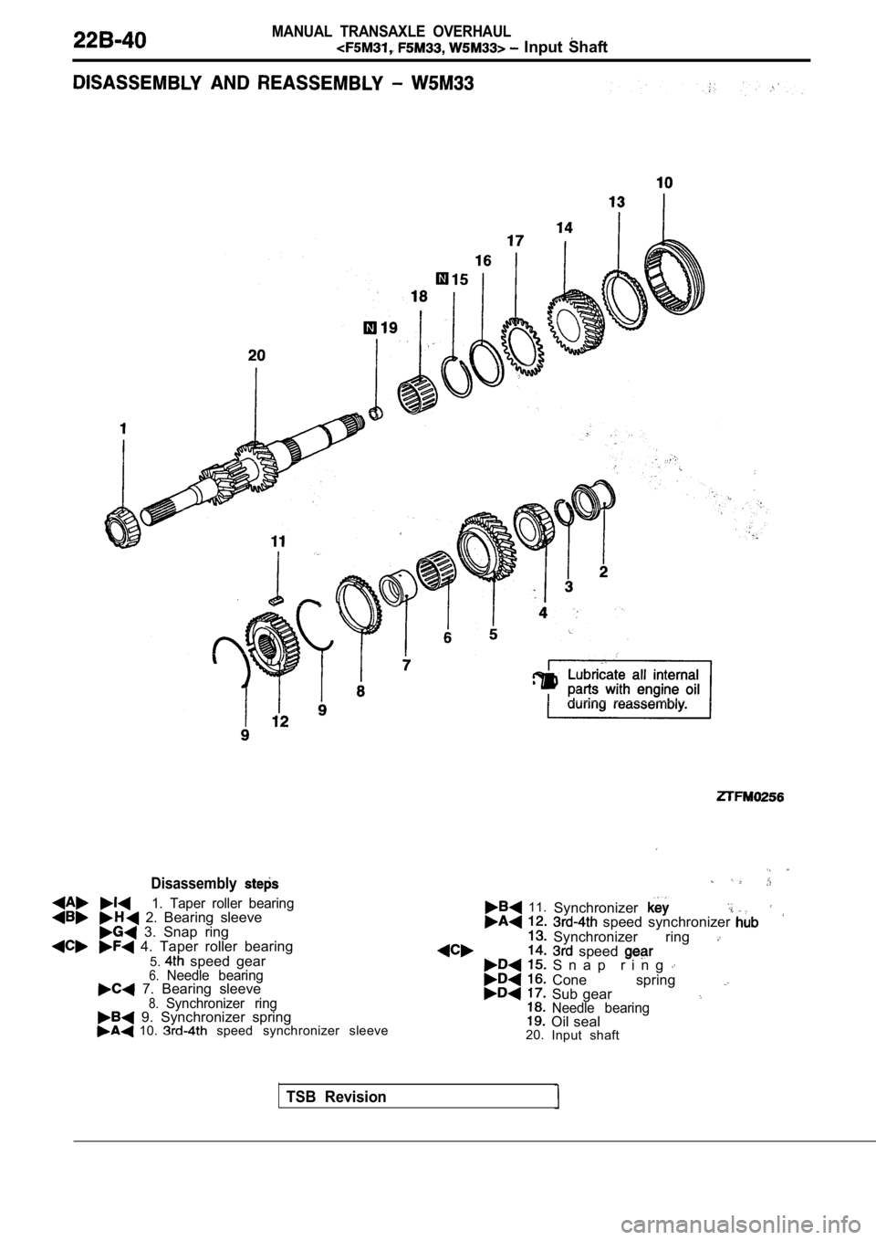
Disassembly
1. Taper roller bearing 2. Bearing sleeve 3. Snap ring 4. Taper roller bearing5.
speed gear6.Needle bearing 7. Bearing sleeve8.Synchronizer ring 9. Synchronizer spring 10. speed synchronizer sleeve
11.Synchronizer speed synchronizer
Synchronizer ring speed S n a p r i n g
Cone spring Sub gearNeedle bearingOil sealInput shaft
20.
TSB Revision
Trending: fuel type, radiator, trunk, steering, heater, ECU, check engine
![MITSUBISHI SPYDER 1990 Service Repair Manual MANUAL TRANSAXLE OVERHAUL
Transaxle
IDLER GEAR SHAFT BOLT
INSTALLATION
(1)Center the shaft with a Phillips screwdriver [shaft diameter
8 mm in.)] or the like.
(2) Tighten the re MITSUBISHI SPYDER 1990 Service Repair Manual MANUAL TRANSAXLE OVERHAUL
Transaxle
IDLER GEAR SHAFT BOLT
INSTALLATION
(1)Center the shaft with a Phillips screwdriver [shaft diameter
8 mm in.)] or the like.
(2) Tighten the re](/img/19/57345/w960_57345-920.png)
