MITSUBISHI SPYDER 1990 Service Repair Manual
Manufacturer: MITSUBISHI, Model Year: 1990, Model line: SPYDER, Model: MITSUBISHI SPYDER 1990Pages: 2103, PDF Size: 68.98 MB
Page 881 of 2103
MANUAL TRANSAXLE (NON-TURBO)> General
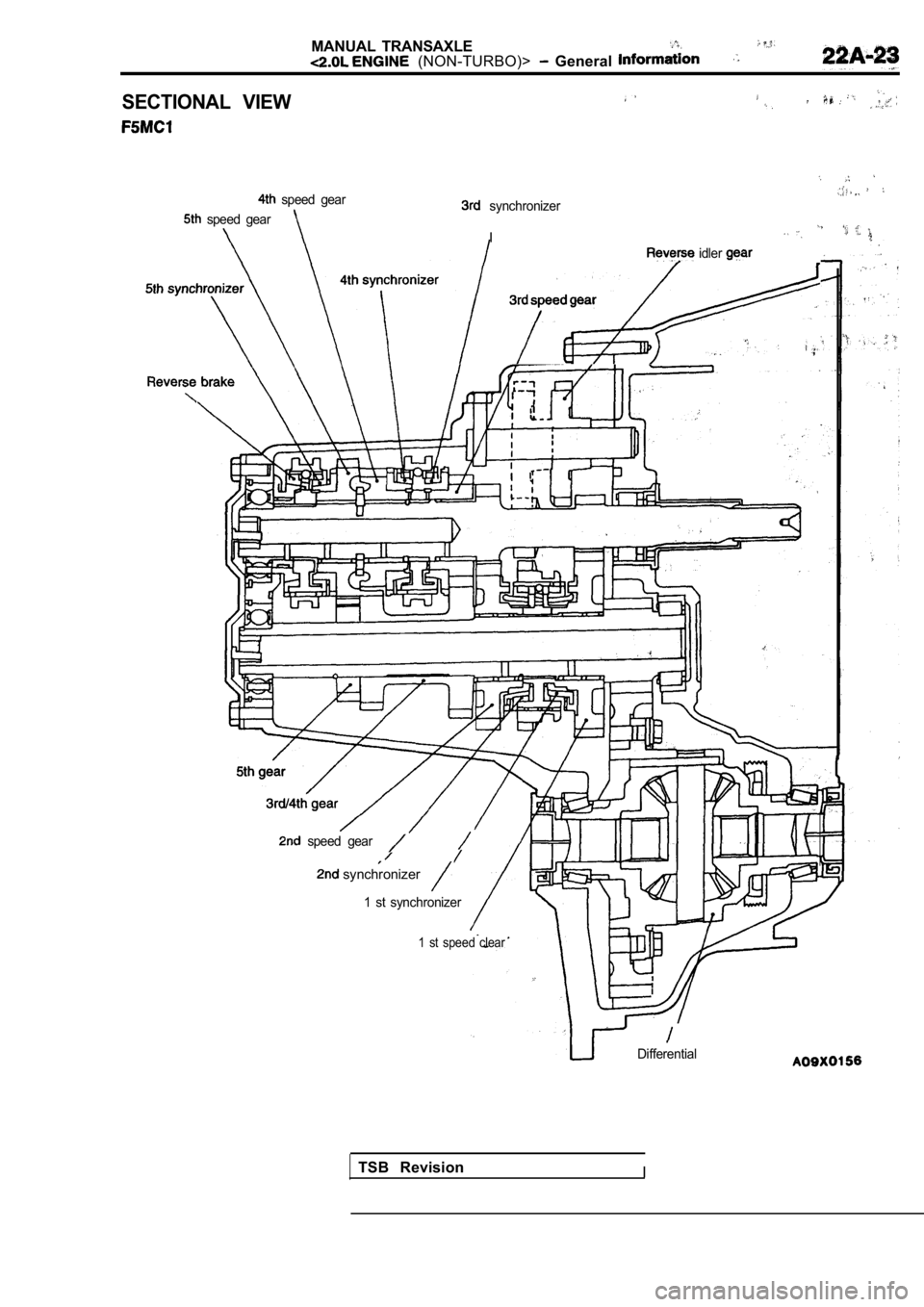
SECTIONAL VIEW
synchronizer
I
speed gear
speed gear
idler
,
speed gear
synchronizer
1 st synchronizer
1 st speed clear
Differential
TSB RevisionI
Page 882 of 2103
MANUAL
ENGINE (NON-TURBO)>
Service Specifications/Lubricants/
Special Tools/Troubleshooting/On-vehicle Service
SERVICE SPECIFICATIONS22100020010
ItemsStandard value
Installation dimension of front roll stopper bracke t 43 3 (1.69
LUBRICANTS22110020025
ItemsSpecified lubricantQuantity (qts.)
Transaxle oil TEXACO MTX FLUID FM
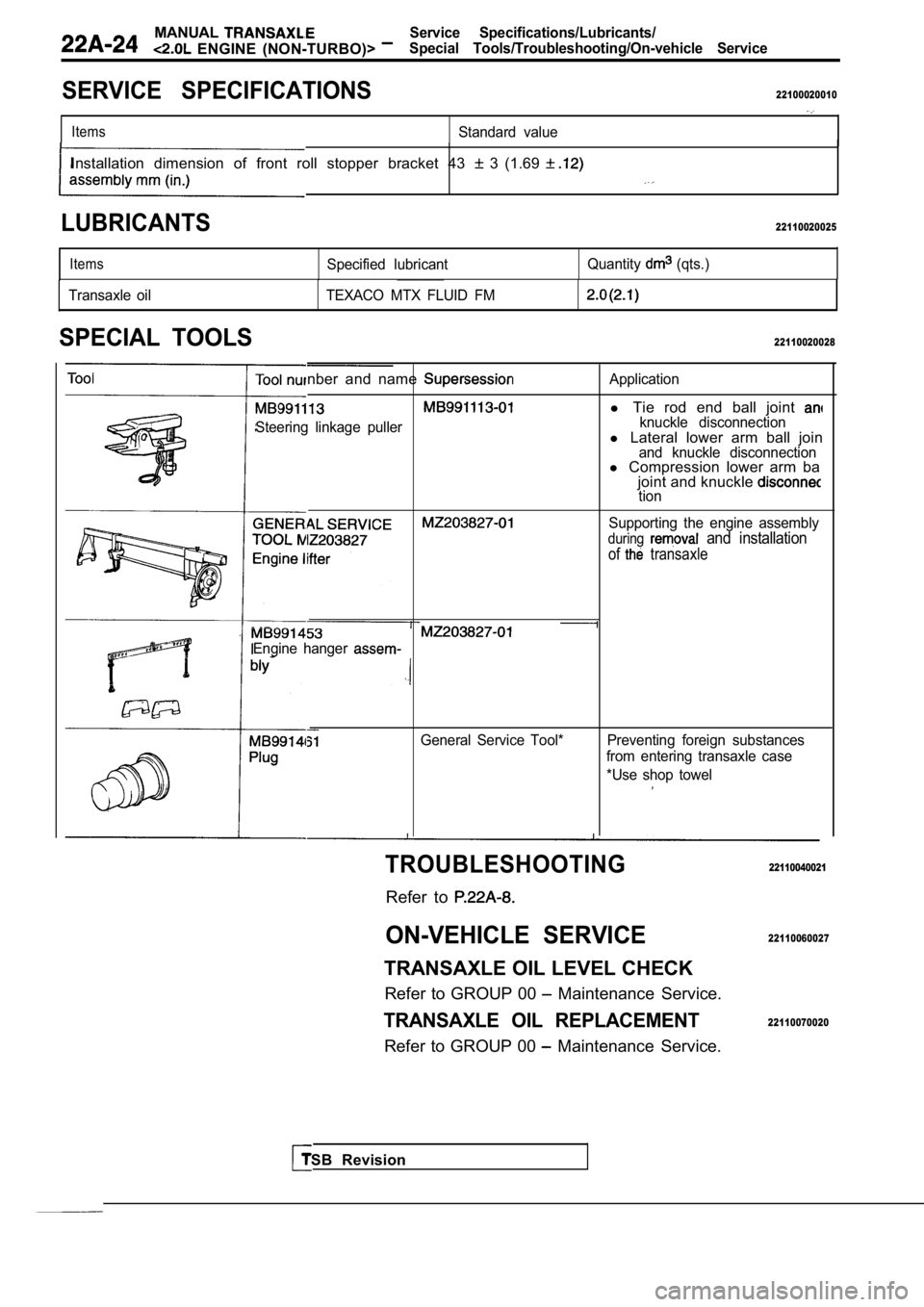
SPECIAL TOOLS22110020028
nber and name
Steering linkage puller
Application
l Tie rod end ball joint knuckle disconnectionl Lateral lower arm ball joinand knuckle disconnectionl Compression lower arm ba
joint and knuckle
tion
Supporting the engine assembly
during and installation
of transaxle
Engine hanger
General Service Tool* Preventing foreign substances from entering transaxle case
*Use shop towel
TSB Revision
TROUBLESHOOTING
Refer to
ON-VEHICLE SERVICE
TRANSAXLE OIL LEVEL CHECK
Refer to GROUP 00
Maintenance Service.
TRANSAXLE OIL REPLACEMENT
Refer to GROUP 00 Maintenance Service.
22110040021
22110060027
22110070020
Page 883 of 2103
MANUAL TRANSAXLE ENGINE (NON-TURBO)> Transaxle
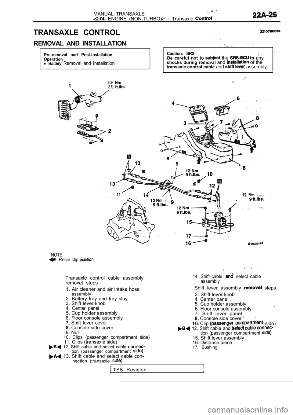
TRANSAXLE CONTROL
REMOVAL AND INSTALLATION
Pre-removal and Post-installationOperationl Removal and Installation
3.9 Nm2.9
,I
Caution: SRS ,
Be careful not to the any
shocks during removal and of the
transaxle control cable and assembly.
12
l 11,
NOTE Resin clip
. .
Transaxle control cable assembly
removal steps
1. Air cleaner and air intake hose assembly
2. Battery tray and tray stay
3. Shift lever knob
4. Center panel5. Cup holder assembly
6. Floor console assembly
7. Shift lever cover
8. Console side cover
9. Nut
10. Clips (passenger compartment side)11. Clips (transaxle side)
14. Shift cable. select cable
assembly
Shift lever assembly steps
3. Shift lever knob
4. Center panel
5. Cup holder assembly
6. Floor console assembly ,
7. Shift lever panel
8. Console side cover’”
Clip side) 12. Shift cable and
12. Shift cable and select cable tion (passenger compartment
13. Shift cable and select cable con-
nection (transaxle
tion (passenger compartment
15. Shift lever assembly
16. Distance piece
TSB Revision 17. Bushing
Page 884 of 2103
MANUAL TRANSAXLE ENGINE (NON-TURBO)> Transaxle Control
Select cable
Shift lever
Neutral position1
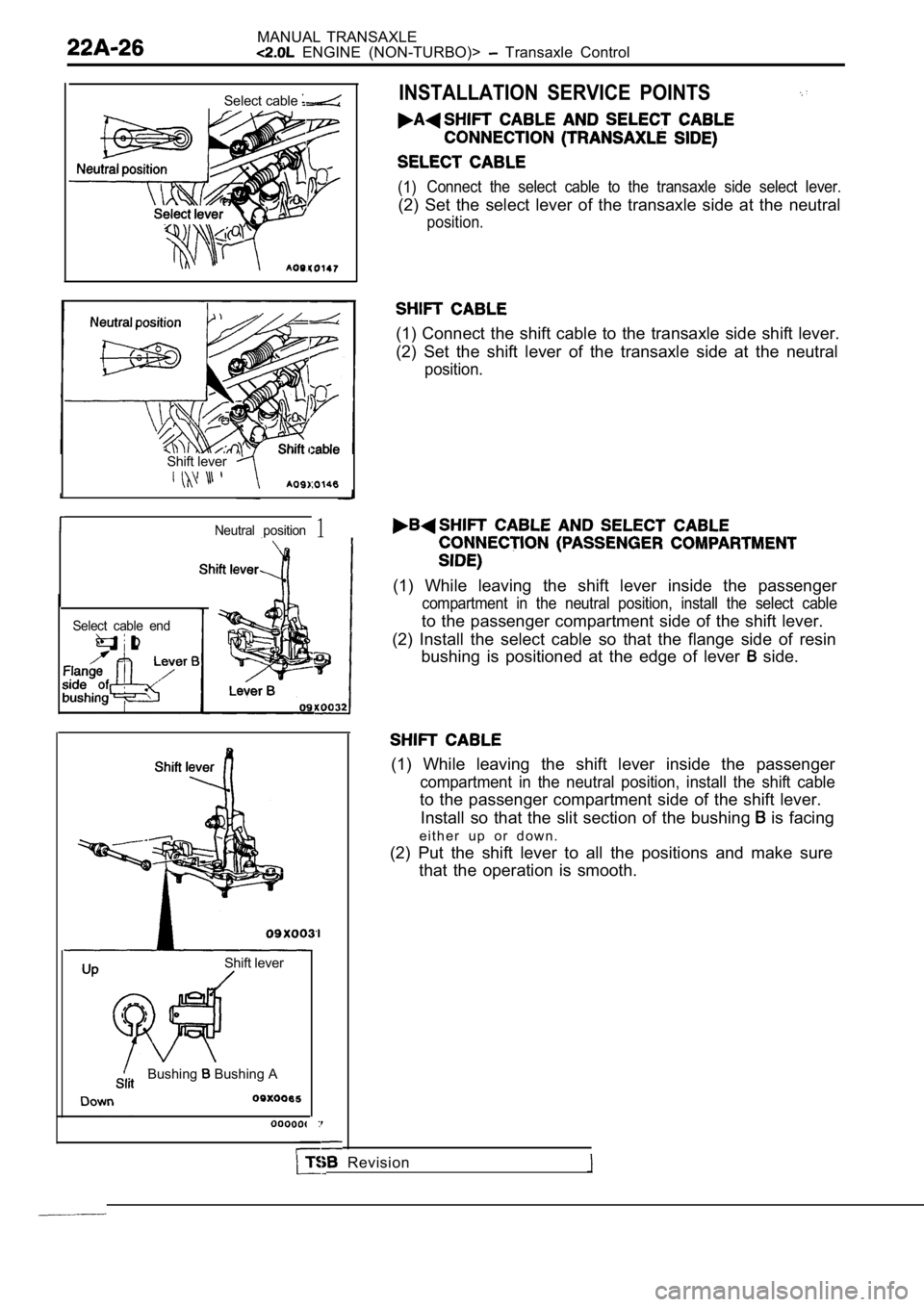
INSTALLATION SERVICE POINTS
(1) Connect the select cable to the transaxle side sele
ct lever.
(2) Set the select lever of the transaxle side at the neutral
position.
(1) Connect the shift cable to the transaxle side s hift lever.
(2) Set the shift lever of the transaxle side at th e neutral
position.
(1) While leaving the shift lever inside the passen ger
compartment in the neutral position, install the select cable
to the passenger compartment side of the shift leve r.
(2) Install the select cable so that the flange sid e of resin
bushing is positioned at the edge of lever
side.
Select cable end
(1) While leaving the shift lever inside the passen ger
compartment in the neutral position, install the shift cable
to the passenger compartment side of the shift leve r.
Install so that the slit section of the bushing
is facing
e i t h e r u p o r d o w n .
(2) Put the shift lever to all the positions and ma ke sure
that the operation is smooth.
Shift lever
Bushing
Bushing A
Revision
Page 885 of 2103
MANUAL TRANSAXLE .
ENGINE Transaxle
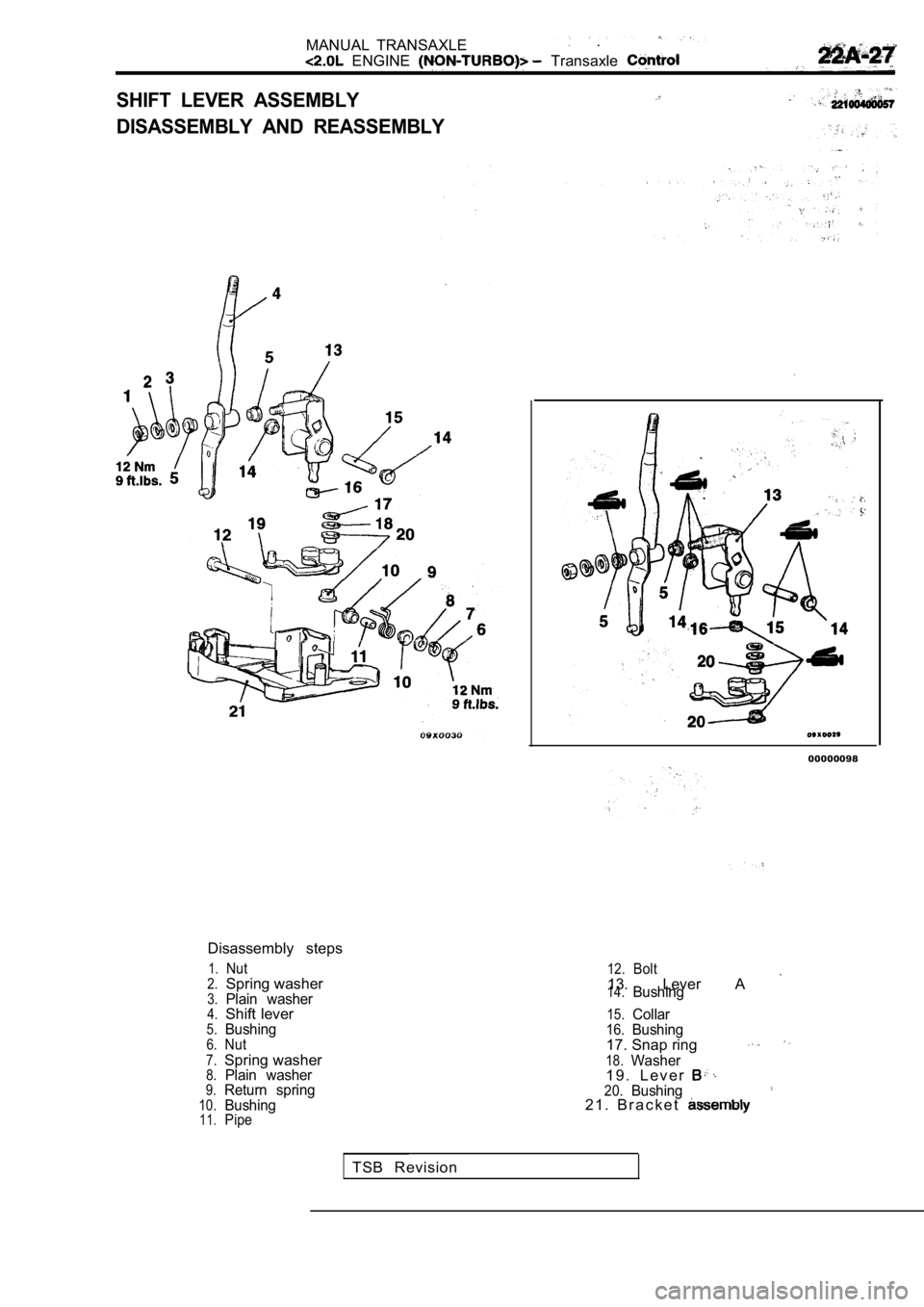
SHIFT LEVER ASSEMBLY
DISASSEMBLY AND REASSEMBLY
Disassembly steps
1.Nut2.Spring washer3.Plain washer4.Shift lever5.Bushing6.Nut
7.Spring washer8.Plain washer9.Return spring10.Bushing11.Pipe
00000098
12.Bolt13. Lever A 14.Bushing
15.Collar16.Bushing17. Snap ring
18.Washer1 9 . L e v e r 20.Bushing2 1 . B r a c k e t
TSB Revision
Page 886 of 2103
MANUAL TRANSAXLE
ENGINE (NON-TURBO)> Transaxle Control
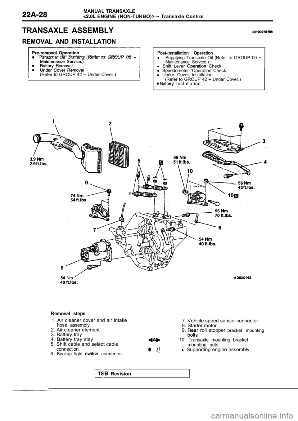
TRANSAXLE ASSEMBLY
REMOVAL AND INSTALLATION
l Transaxle Oil Draining (Refer to GROUP 00
(Refer to GROUP 42 Under Cover.)
Post-installation Operationl
Supplying Transaxle Oil (Refer to GROUP 00 Maintenance Service.)l Shift Lever Check
l Speedometer ‘Operation Check
l Under Cover Installation
(Refer to GROUP 42
Under Cover.) I n s t a l l a t i o n
8
54Nm
Removal steps
1. Air cleaner cover and air intakehose assembly2. Air cleaner element
3. Battery tray
4. Battery tray stay
5. Shift cable and select cable
connection6. Backup light connectorl b
7. Vehicle speed sensor connector
8. Starter motor
9.
roll stopper bracket mounting
10. Transaxle mounting bracket
mounting nuts
l Supporting engine assembly
Revision
Page 887 of 2103
MANUAL TRANSAXLE
ENGINE (NON-TURBO)> Transaxle
2418
75Nm5 5
59-71 NmI
13
16
Nm
65
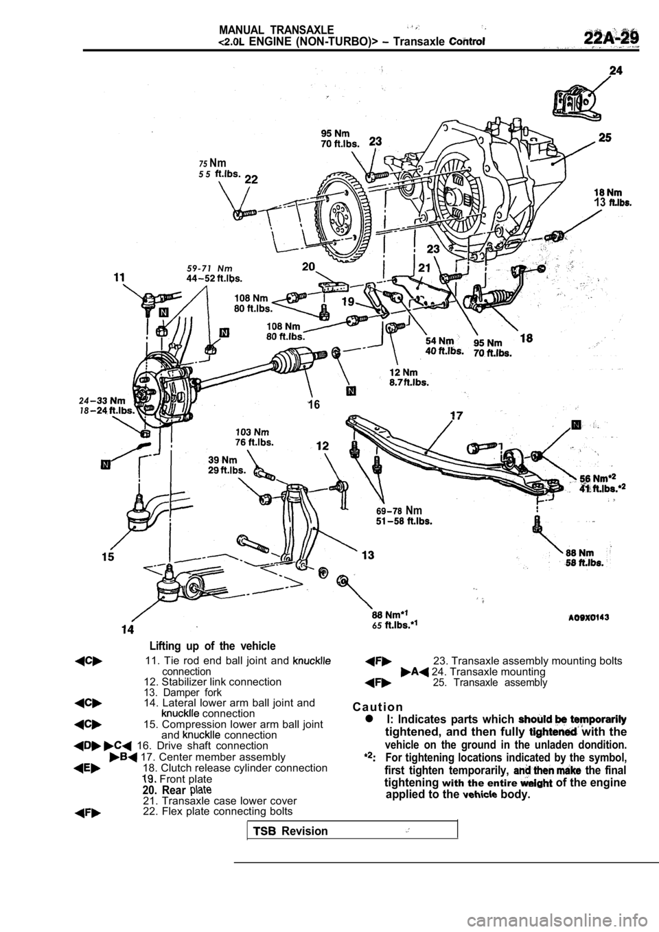
Lifting up of the vehicle
11. Tie rod end ball joint and connection12. Stabilizer link connection13. Damper fork14. Lateral lower arm ball joint and connection15. Compression lower arm ball joint
and connection 16. Drive shaft connection
17. Center member assembly18. Clutch release cylinder connection
Front plate
20. Rear 21. Transaxle case lower cover22. Flex plate connecting bolts
Revision
23. Transaxle assembly mounting bolts 24. Transaxle mounting25. Transaxle assembly
C a u t i o n
l l: Indicates parts which
tightened, and then fully with the
vehicle on the ground in the unladen dondition.
For tightening locations indicated by the symbol,
first tighten temporarily, the final
tighteningwith the entire of the engine
applied to the
body.
Page 888 of 2103
MANUAL TRANSAXLE
(NON-TURBO)> Transaxle Control
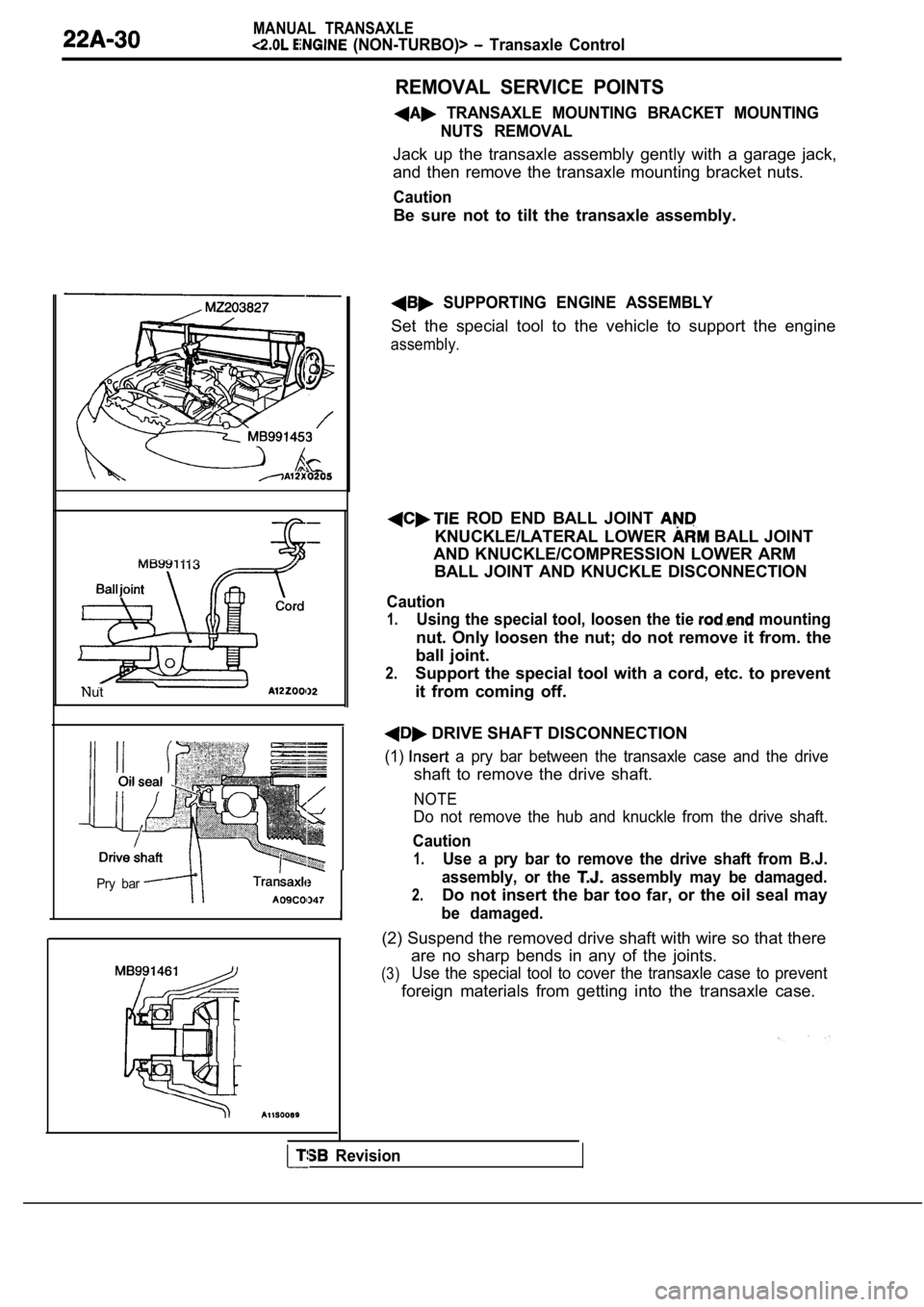
REMOVAL SERVICE POINTS
TRANSAXLE MOUNTING BRACKET MOUNTINGNUTS REMOVAL
Jack up the transaxle assembly gently with a garage jack,
and then remove the transaxle mounting bracket nuts .
Caution
Be sure not to tilt the transaxle assembly.
Nut
Pry bar
I
SUPPORTING ENGINE ASSEMBLY
Set the special tool to the vehicle to support the engine
assembly.
ROD END BALL JOINT
KNUCKLE/LATERAL LOWER BALL JOINT
AND KNUCKLE/COMPRESSION LOWER ARM BALL JOINT AND KNUCKLE DISCONNECTION
Caution
1.Using the special tool, loosen the tie mounting
nut. Only loosen the nut; do not remove it from. th e
ball joint.
2.Support the special tool with a cord, etc. to preve nt
it from coming off.
DRIVE SHAFT DISCONNECTION
(1) a pry bar between the transaxle case and the drive
shaft to remove the drive shaft.
NOTE
Do not remove the hub and knuckle from the drive sh aft.
Caution
1.Use a pry bar to remove the drive shaft from B.J.
2.
assembly, or the assembly may be damaged.
Do not insert the bar too far, or the oil seal may
be damaged.
(2) Suspend the removed drive shaft with wire so that there
(3)
are no sharp bends in any of the joints.
Use the special tool to cover the transaxle case to prevent
foreign materials from getting into the transaxle c ase.
Revision
Page 889 of 2103
MANUAL TRANSAXLE
ENGINE (NON-TURBO)>
TransaxlemountTransaxle side l
stopper.Arrow
Transaxle
mountbracket
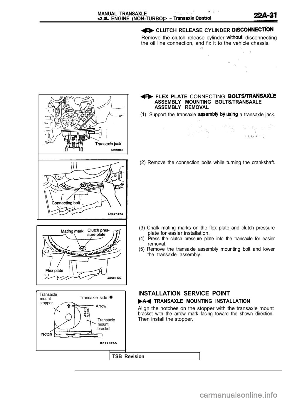
CLUTCH RELEASE CYLINDER
Remove the clutch release cylinder disconnecting
the oil line connection, and fix it to the vehicle chassis.
,
FLEX PLATE CONNECTING
ASSEMBLY MOUNTING BOLTS/TRANSAXLE
ASSEMBLY REMOVAL
(1)Support the transaxle a transaxle jack.
(2) Remove the connection bolts while turning the c rankshaft.
(3) Chalk mating marks on the flex plate and clutch pressure
plate for easier installation.
(4)Press the clutch pressure plate into the transaxle for easier
removal.
(5) Remove the transaxle assembly mounting bolt and lower
the transaxle assembly.
INSTALLATION SERVICE POINT
TRANSAXLE MOUNTING INSTALLATION
Align the notches on the stopper with the transaxle mount
bracket with the arrow mark facing toward the shown direction.
Then install the stopper.
TSB Revision
Page 890 of 2103
MANUAL. TRANSAXLE
ENGINE (NON-TURBO)> Transaxle Control
Frontstopper
bracket
member
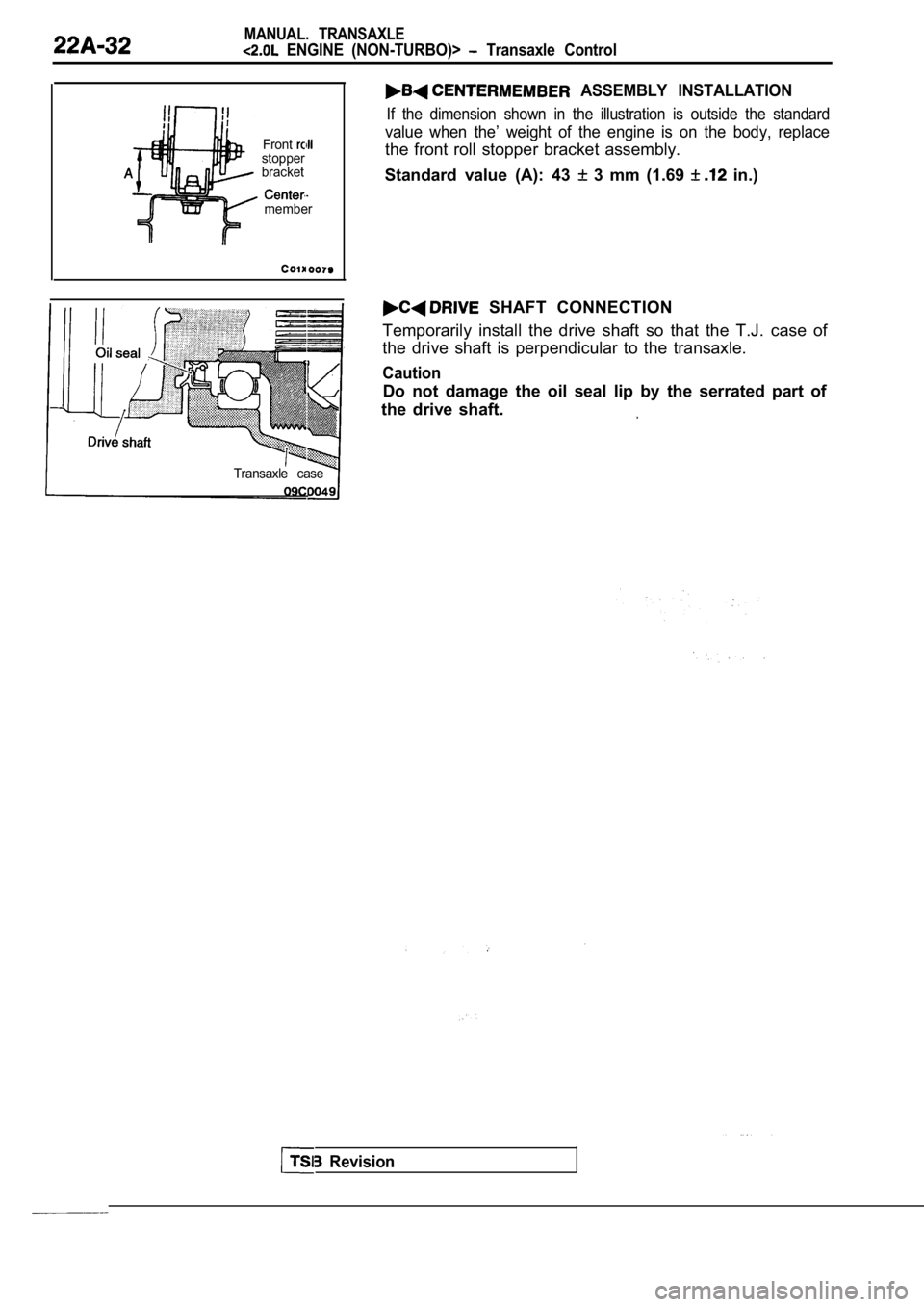
ASSEMBLY INSTALLATION
If the dimension shown in the illustration is outside the standard
value when the’ weight of the engine is on the body , replace
the front roll stopper bracket assembly.
Standard value (A): 43
3 mm (1.69 in.)
SHAFT CONNECTION
Temporarily install the drive shaft so that the T.J . case of
the drive shaft is perpendicular to the transaxle.
Caution
Do not damage the oil seal lip by the serrated part of
the drive shaft.
Transaxle case
Revision