NISSAN ALMERA N15 1995 Service Manual
Manufacturer: NISSAN, Model Year: 1995, Model line: ALMERA N15, Model: NISSAN ALMERA N15 1995Pages: 1701, PDF Size: 82.27 MB
Page 1551 of 1701
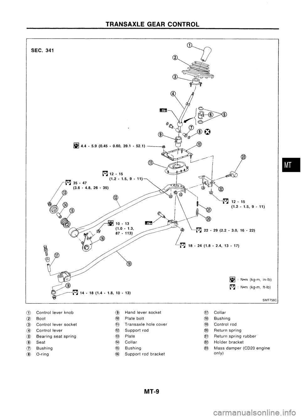
TRANSAXlEGEAR
CONTROL
•
~ .Nom (k
g-m, in-Ib)
~ :Nom (kg-m, ft-Ib)
12
~
4.4.5.9 (0.45
•060
.
,39.1. 52.1)
m
.
..--~~
~~O 't~~~
t"J t"J
12•15
(jj)~~~~l '
3
35 •47 (1.2•15
._le'
(3 6 .,9 •11)
~~
-
.
..--~
/" rIiJ
10.13 ~
I\~~ ~ ;~;
'~.5, 9•11)
, {y"'''
(1.0•
1.3, "",/'
>
"@
'\ _Y 87•113)
I
16
iI5J
t
t"J
22•29 (2.2 .
L,
3.0.16•22)
-~ 18.24(1.8 •2
.4, 13•17)
f?:!-
:g.~
~
14. 18(1
W
.4.18 1
.,
O.13)
SEC.
341
Control leverknb
Boot
0
Control leversocke
Control lever t
Bearing seats.
Seat pring
Bushing
O-ring Hand
Iever socket
Plate bolt
Transaxle hI
S
0
e cover
upport rod
Plate
Collar
Bushing
Support rodbracket
@
@
@)
@
@
@
@
Collar
Bushing
Control rod
Return spring
Return s.
pring rubb
Hold er
er bracket
Mass dame
only) pr(CD20 engine
MT-9
Page 1552 of 1701
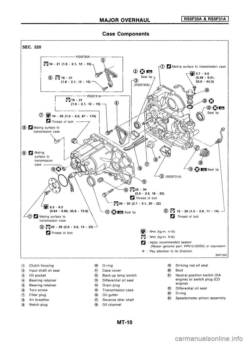
SEC.320 MAJOR
OVERHAUL
Case Components
I
RS5F30A
&
RS5F31 A
I
.. -- RS5F31A---
~16 -21
(1.6 -2.1, 12. 15)
@ ~Mating
surface to
transmiSSion
case ----
@
~20 -29 (2.0 -3.0, 14-22)-
~ Thread ofbolt
(1)
Clutch housing
@)
O-ring
@
Input shaftoilseal
@
Case cover
@
Oilpocket
@
Back-up lampswitch
@
Bearing retainer
@
Differential oilseal
@
Bearing retainer
@
Drain plug
@
Torx screw
@l
Transmission case
(J)
Filler plug
@
Oilgutter
@
Airbreather
@
Reverse idlershaft
@
Welch plug
@
Oilchannel
MT-10
@
~
15-20 (1.5 -2.0, 11-14)
~ Thread ofbolt
Ij] :
Nom (kg-m, in-Ib)
tr'J :
Nom (kg-m, ft-Ib)
~ :Apply recommended sealant
(Nissan genuine part:KP610-00250) orequivalent.
*: :
Pay attention toits direction.
SMT755C
@
Striking rodoilseal
@J
Boot
@
Neutral position switch(GA
engine) orswitch plug(CD
engine)
@
Differential oilseal
@
O-ring
@
Speedometer pinionassembly
Page 1553 of 1701
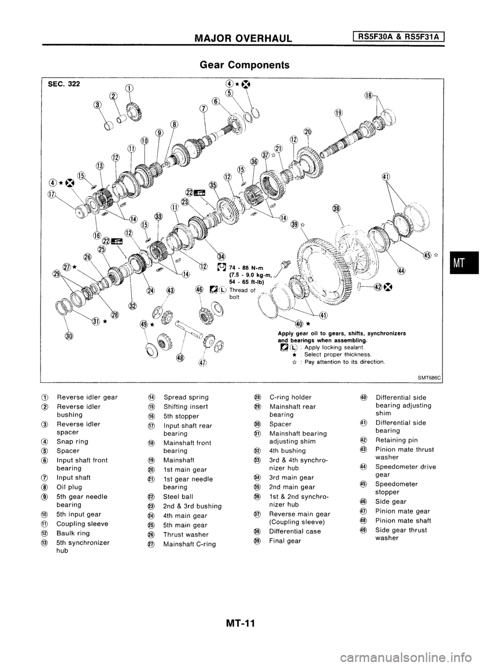
MAJOROVERHAUL
I
RS5F30A
&
RS5F31 A
I
SEC. 322
G)
Reverse
idlergear
@
Spread spring
@
Reverse idler
@
Shifting insert
bushing
@
5thstopper
@
Reverse idler
@
Input shaft rear
spacer bearing
@
Snap ring
@
Mainshaft front
@
Spacer bearing
@
Input shaftfront
@l
Mainshaft
bearing
@J
1st
main gear
(]) Input shaft
@
1stgear needle
@
Oilplug bearing
@
5th
gear needle
@
Steel ball
bearing
@
2nd
&
3rd bushing
@
5thinput gear
@
4thmain gear
@
Coupling sleeve
@
5thmain gear
@
Baulk ring
@
Thrust washer
@
5thsynchronizer
@
Mainshaft C-ring
hub
45
t:r
Apply gearoiltogears, shifts.synchronizers
and bearings whenassembling.
~ (iJ :
Apply locking sealant
* .
Select proper thickness.
11 :
Pay attention toits direction.
SMT686C
@
C-ring holder
@)
Differential side
@
Mainshaft rear bearing
adjusting
bearing shim
@
Spacer
@
Differential side
@
Mainshaft bearing bearing
adjusting shim
@
Retaining pin
@
4thbushing
@
Pinion matethrust
@
3rd
&
4th synchro- washer
nizer hub
@
Speedometer drive
@
3rdmain gear gear
@
2ndmain gear
@
Speedometer
@
1st
&
2nd synchro- stopper
nizer hub
@
Side gear
@
Reverse maingear
@
Pinion mategear
(Coupling sleeve)
@
Pinion mateshaft
@
Differential case
@
Side gearthrust
@
Final gear washer
MT-11
•
Page 1554 of 1701
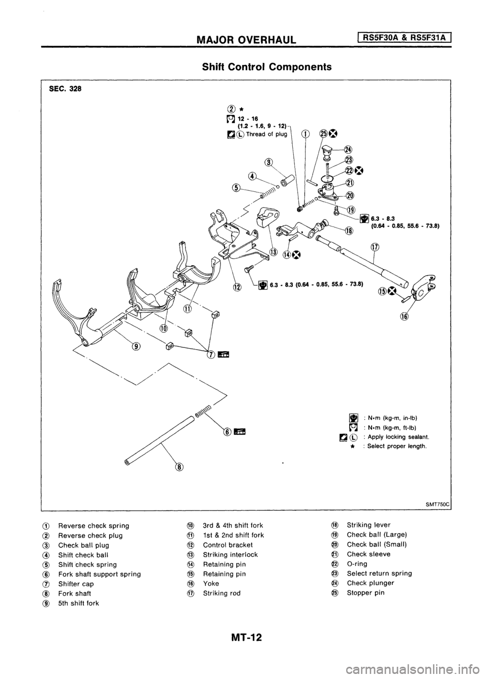
SEC.328 MAJOR
OVERHAUL
Shift Control Components
I
RS5F30A
&
RS5F31A
I
@*
[OJ
12.16
(1.2 •1.6, 9•
12)
~ Ch>
Thread ofplug
~ \~ 6.3•U (0.64 •0.6'. 55.6•13.61
~ :N.m (kg-m. in-Ib)
[OJ :
N.m (kg-m. ft-Ib)
~ Ch> :
Apply locking sealant.
* :Select proper length.
SMT750C
G)
Reverse checkspring
@
Reverse checkplug
@
Check ballplug
@
Shift check ball
@
Shiftcheck spring
@
Fork shaft support spring
(J)
Shifter cap
@
Fork shaft
@
5thshift fork
@
3rd
&
4th shift fork
@
1st
&
2nd shift fork
@
Control bracket
@
Striking interlock
@ Retaining pin
@)
Retaining pin
@)
Yoke
@
Striking rod
MT-12
@
Striking lever
@
Check ball(Large)
@J
Check ball(Small)
@
Check sleeve
@
G-ring
@
Select returnspring
@
Check plunger
@
Stopper pin
Page 1555 of 1701
DISASSEMBLV
I
RSSF30A
&
RSSF31 A
I
5th shift -
fork
Suitable
tool
SMT571
SMT082A SMT577
SMT579
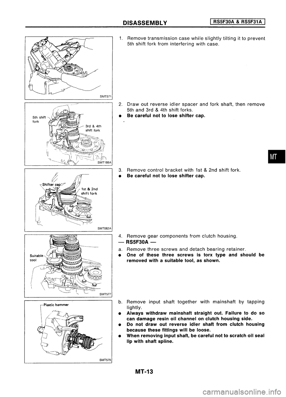
1.
Remove transmission casewhile slightly tiltingitto prevent
5th shift forkfrom interfering withcase.
2. Draw outreverse idlerspacer andfork shaft, thenremove
5th and 3rd
&
4th shift forks.
• Becareful nottolose shifter cap.
3. Remove controlbracket with1st
&
2nd shift fork.
• Becareful nottolose shifter cap.
4. Remove gearcomponents fromclutch housing.
- RS5F30A-
a. Remove threescrews anddetach bearing retainer.
• One ofthese threescrews istorx type andshould be
removed withasuitable tool,asshown.
b. Remove inputshafttogether withmainshaft bytapping
lightly.
• Always withdraw mainshaft straightout.Failure todo so
can damage resinoilchannel onclutch housing side.
• Do not draw outreverse idlershaft fromclutch housing
because thesefittings willbeloose.
• When removing inputshaft, becareful nottoscratch oilseal
lip with shaft spline.
MT-13
•
Page 1556 of 1701
DISASSEMBLY
I
RS5F30A
&
RS5F31 A
I
SMT580
SMT720
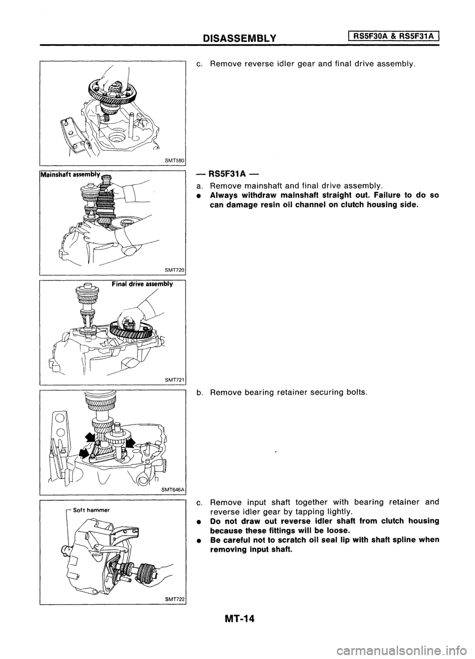
c.
Remove reverseidlergear andfinal drive assembly.
- RS5F31A-
a. Remove mainshaft andfinal drive assembly.
• Always withdraw mainshaft straightout.Failure todo so
can damage resinoilchannel onclutch housing side.
SMT721
SMT646A
Soft hammer
SMT722
b.
Remove bearingretainer securing bolts.
c. Remove inputshaft together withbearing retainer and
reverse idlergear bytapping lightly.
• Do not draw outreverse idlershaft fromclutch housing
because thesefittings willbeloose.
• Becareful nottoscratch oilseal lipwith shaft spline when
removing inputshaft.
MT-14
Page 1557 of 1701
DISASSEMBLY RS5F30A
&
RS5F31 A
SMT648AA
KV32101000
SMT599AA
SMT583
/ Reverse checkplug
~ "Reverse checkspring
S/
V
Check ball(Large)
"--_Check ball(Small)
SMT584
SMT585
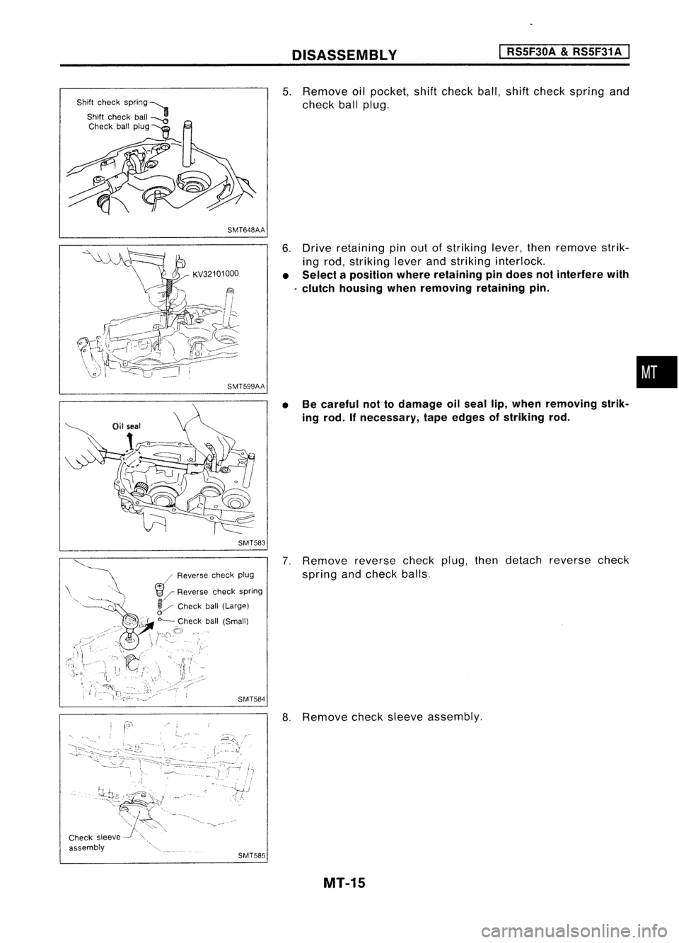
5.
Remove oilpocket, shiftcheck ball,shift check spring and
check ballplug.
6. Drive retaining pinout ofstriking lever,thenremove strik-
ing rod, striking leverandstriking interlock.
• Select aposition whereretaining pindoes notinterfere with
. clutch housing whenremoving retainingpin.
• Becareful nottodamage oilseal lip,when removing strik-
ing rod. Ifnecessary, tapeedges ofstriking rod.
7. Remove reversecheckplug,thendetach reverse check
spring andcheck balls,
8. Remove checksleeve assembly.
MT-15
•
Page 1558 of 1701
REPAIRFORCOMPONENT PARTS
I
RS5F30A
&
RS5F31 A
I
~EndPlaY
Gear
Needlebearing
SMT734A
5th synchronizer hub
Input
Shaft andGears
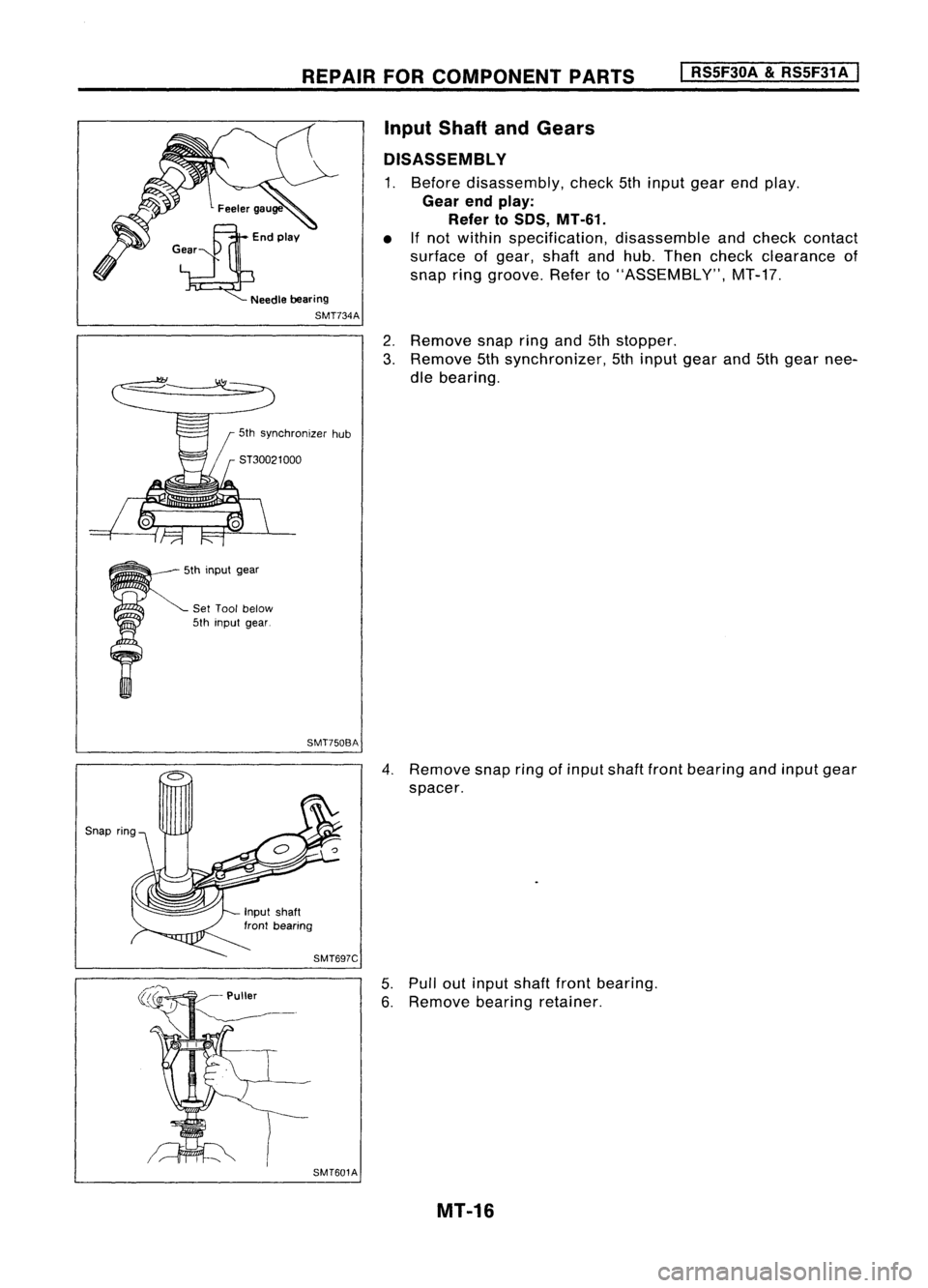
DISASSEMBLY
1. Before disassembly, check5thinput gearendplay.
Gear endplay:
Refer toSOS, MT-61.
• Ifnot within specification, disassembleandcheck contact
surface ofgear, shaftandhub. Then check clearance of
snap ringgroove. Referto"ASSEMBLY", MT-17.
2. Remove snapringand5thstopper.
3. Remove 5thsynchronizer, 5thinput gearand5thgear nee-
dle bearing.
5th input gear
Set Tool below
5th input gear.
SMT750BA
SMT601A
4.
Remove snapringofinput shaftfrontbearing andinput gear
spacer.
5. Pull outinput shaftfrontbearing.
6. Remove bearingretainer.
MT-16
Page 1559 of 1701
Shiftinginsert
t
Baulkringto
gear clearance
REPAIR
FORCOMPONENT PARTS
I
RS5F30A
&
RS5F31A
I
Input Shaft andGears (Cont'd)
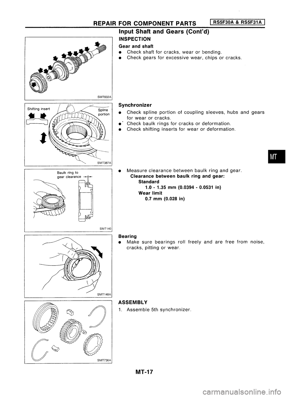
INSPECTION
Gear andshaft
• Check shaftforcracks, wearorbending.
• Check gearsforexcessive wear,chipsorcracks.
SMT602A Synchronizer
• Check splineportion ofcoupling sleeves,hubsandgears
for wear orcracks.
• Check baulkringsforcracks ordeformation.
• Check shifting insertsforwear ordeformation.
SMT387A
•Measure clearance betweenbaulkringandgear.
Clearance betweenbaulkringandgear:
Standard 1.0 -1.35 mm(0.0394 -0.0531 in)
Wear limit
0.7 mm (0.028 in)
SMT140
•
Bearing
• Make surebearings rollfreely andarefree from noise,
cracks, pittingorwear.
SMT148A ASSEMBLY
1. Assemble 5thsynchronizer.
MT-17
Page 1560 of 1701
SMT7618
5T37750000
REPAIR
FORCOMPONENT PARTS
I
RS5F30A
&
RS5F31A
I
Input Shaft andGears (Cont'd)
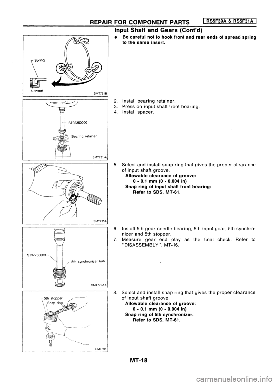
• Becareful nottohook frontandrear ends ofspread spring
to the same insert.
2. Install bearing retainer.
3. Press oninput shaftfrontbearing.
4. Install spacer.
~" O~0Bearing retainer
~~ SMT731-A
5.Select andinstall snapringthatgives theproper clearance
of input shaftgroove.
Allowable clearanceofgroove:
o -
0.1 mm (0-0.004 in)
Snap ringofinput shaftfrontbearing:
Refer toSOS, MT-61.
6. Install 5thgear needle bearing, 5thinput gear, 5thsynchro-
nizer and5thstopper.
7. Measure gearendplayas thefinal check. Referto
"DISASSEMBLY", MT-16.
5th synchronizer hub
SMT779AA
8.Select andinstall snapringthatgives theproper clearance
of input shaftgroove.
Allowable clearanceofgroove:
0-0.1 mm(0-0.004 in)
Snap ringof5th synchronizer:
Refer toSOS, MT-61.
SMT591 MT-18