NISSAN ALMERA N15 1995 Service Manual
Manufacturer: NISSAN, Model Year: 1995, Model line: ALMERA N15, Model: NISSAN ALMERA N15 1995Pages: 1701, PDF Size: 82.27 MB
Page 1561 of 1701
REPAIRFORCOMPONENT PARTS
I
RS5F30A &RS5F31 A
I
Mainshaft andGears
DISASSEMBL Y
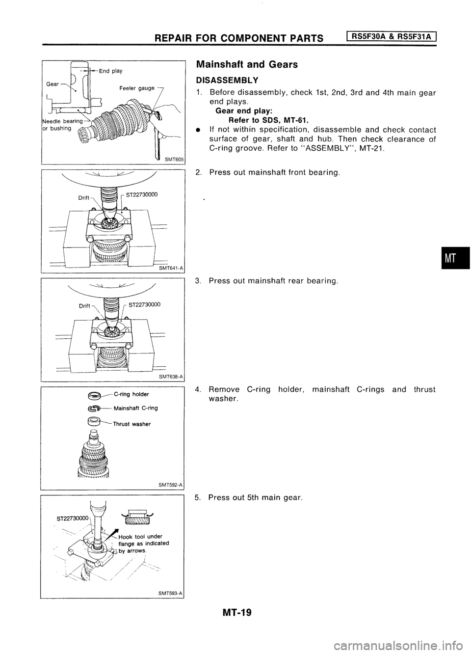
1. Before disassembly, check1st,2nd, 3rdand 4thmain gear
end plays.
Gear endplay:
Refer to50S, MT-61.
• Ifnot within specification, disassembleandcheck contact
surface ofgear, shaftandhub. Then check clearance of
C-ring groove. Referto"ASSEMBLY", MT-21.
2. Press outmainshaft frontbearing.
ST22730000
SMT641-A
3.Press outmainshaft rearbearing.
SMT638-A
•
~ C-ringholder
~~ Mainshaft C-ring
8---
Thrustwasher
SMT592-A
5T,22730, OOO~~""~/
i~;~<~:(
-----~"
"~"
-'::-.
,---'/Hooktoolunder
-', """.•".~, >~\ .
J.
flange asindicated
'. '.~ byarrows.
"-~,
",'
.'
//
" /!~'(';Y
I -\--...
Y:<"~_.
~~w"-,~
--...' ....~"'I "
SMT593-A
4.
Remove C-ringholder, mainshaft C-ringsandthrust
washer.
5. Press out5th main gear.
MT-19
Page 1562 of 1701
SMT687C
Steel
ball
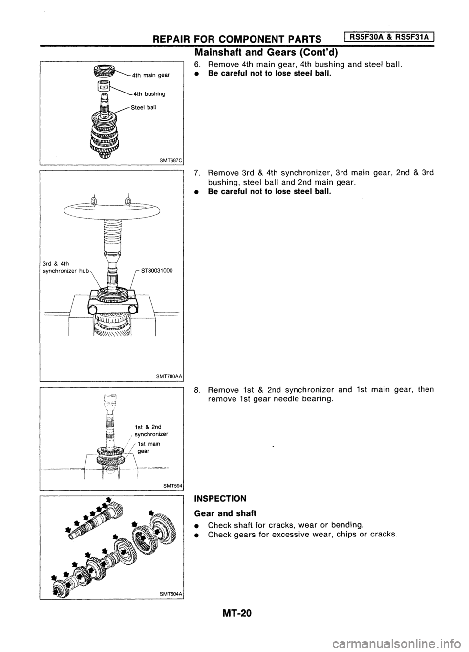
7.Remove 3rd
&
4th synchronizer, 3rdmain gear, 2nd
&
3rd
bushing, steelballand2nd main gear.
• Becareful nottolose steel ball.
REPAIR
FORCOMPONENT PARTS
I
RS5F30A
&
RS5F31A
I
Mainshaft andGears (Conl'd)
6. Remove 4thmain gear, 4thbushing andsteel ball.
• Becareful nottolose steel ball.
r
ST30031 000
3rd
&
4th
synchronizer hub
SMT780AA
8.Remove 1st
&
2nd synchronizer and1stmain gear, then
remove 1stgear needle bearing.
1st &2nd
, synchronizer
/ /1st main
.~/\ gear
t-r=-~~'c
SMT594
INSPECTION
Gear andshaft
• Check shaftforcracks, wearorbending.
• Check gearsforexcessive wear,chipsorcracks.
MT-20
Page 1563 of 1701
Shiftinginsert
t
Baulkringto
gear clearance
REPAIR
FORCOMPONENT PARTS
I
RS5F30A
&
RS5F31A
I
Mainshaft andGears (Cont'd)
Synchronizer
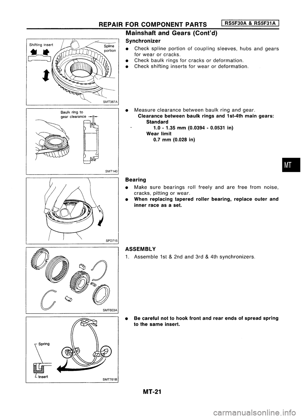
• Check spline portion ofcoupling sleeves,hubsandgears
for wear orcracks.
• Check baulkringsforcracks ordeformation.
• Check shifting insertsforwear ordeformation.
• Measure clearance betweenbaulkringandgear.
Clearance betweenbaulkringsand1st-4th maingears:
Standard 1.0 -1.35 mm(0.0394 -0.0531 in)
Wear limit
0.7 mm (0.028 in)
SMT140
•
SMT761B Bearing
• Make surebearings rollfreely andarefree from noise,
cracks, pittingorwear.
• When replacing taperedrollerbearing, replaceouterand
inner raceasaset.
ASSEMBLY
1. Assemble 1st
&
2nd and 3rd
&
4th synchronizers.
• Becareful nottohook frontandrear ends ofspread spring
to the same insert.
MT-21
Page 1564 of 1701
ST22452000
ST37750000 -
3rd
&
4th
synchronizer hub
REPAIR
FORCOMPONENT PARTS
I
RS5F30A &RS5F31A
I
Mainshaft andGears (Cont'd)
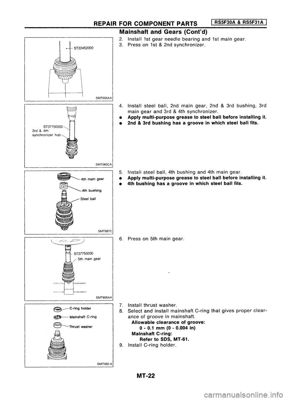
2. Install 1stgear needle bearing and1stmain gear.
3. Press on1st
&
2nd synchronizer.
SMT605AA
4.Install steelball,2ndmain gear, 2nd
&
3rd bushing, 3rd
main gearand3rd
&
4th synchronizer.
• Apply multi-purpose greasetosteel ballbefore installing it.
• 2nd
&
3rd bushing hasagroove inwhich steelballfits.
SMT085CA
5.Install steelball,4thbushing and4thmain gear.
• Apply multi-purpose greasetosteel ballbefore installing it.
• 4th bushing hasagroove inwhich steelballfits.
Steel ball
SMT687C
6.Press on5th main gear.
/ 5th main gear
SMT606AA
~ C-ringholder
~~ Mainshaft C-ring
@---Thrust washer
SMT592-A
7.
Install thrustwasher.
8. Select andinstall mainshaft C-ringthatgives proper clear-
ance ofgroove inmainshaft.
Allowable clearanceofgroove:
0-0.1 mm(O.0.004 in)
Mainshaft C-ring:
Refer to50S, MT-61.
9. Install C-ring holder.
MT-22
Page 1565 of 1701
ST22360002
REPAIR
FORCOMPONENT PARTS
I
RSSF30A
&
RSSF31A
I
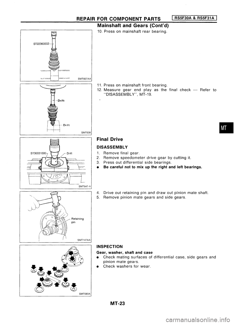
Mainshaft andGears (Cont'd)
10. Press onmainshaft rearbearing.
SMT607AA
11.Press onmainshaft frontbearing.
12. Measure gearendplayas thefinal check -Refer to
"DISASSEM BL
y",
MT-19.
SMT639 FinalDrive
DISASSEMBL Y
1. Remove finalgear.
2. Remove speedometer drivegearbycutting it.
3. Press outdifferential sidebearings.
• Becareful nottomix upthe right andleftbearings.
•
[ .
SMT647-A
4.Drive outretaining pinand draw outpinion mateshaft.
5. Remove pinionmategears andside gears.
Retaining
pin
SMT147AA INSPECTION
Gear, washer, shaftandcase
• Check mating surfaces ofdifferential case,sidegears and
pinion mategears.
• Check washers forwear.
SMT083A MT-23
Page 1566 of 1701
KV38105900
REPAIR
FORCOMPONENT PARTS
I
RS5F30A
&
RS5F31A
I
Final Drive (Conl'd)
Bearing
• Make surebearings rollfreely andarefree from noise,
cracks, pittingorwear.
• When replacing taperedrollerbearing, replaceouterand
inner raceasaset.
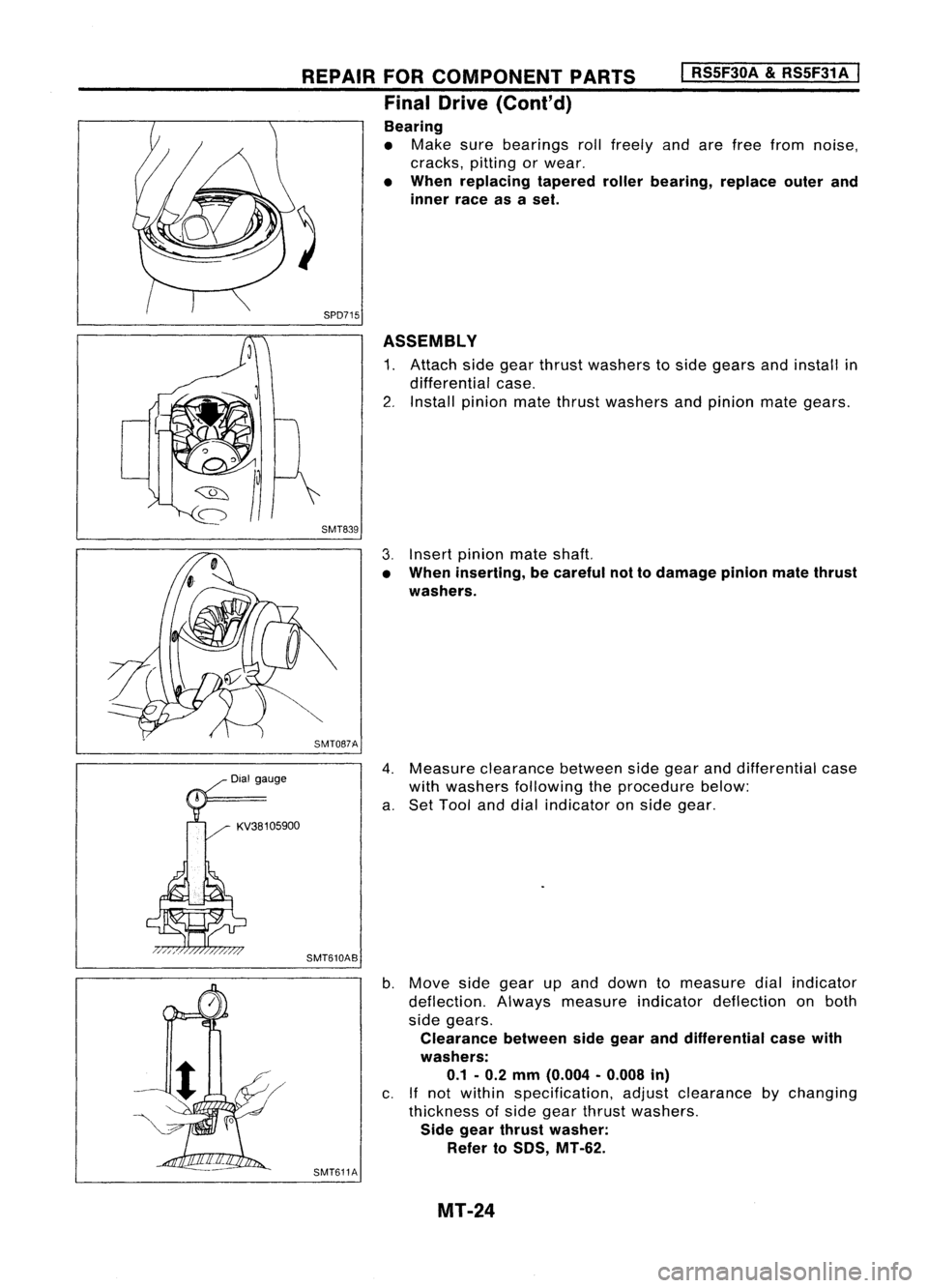
SPD715 ASSEMBLY
1. Attach sidegear thrust washers toside gears andinstall in
differential case.
2. Install pinion matethrust washers andpinion mategears.
SMT839
3.Insert pinion mateshaft.
• When inserting, becareful nottodamage pinionmatethrust
washers.
SMT087A
4.Measure clearance betweensidegear anddifferential case
with washers following theprocedure below:
a. Set Tool anddial indicator onside gear.
SMT610AB
b.Move sidegear upand down tomeasure dialindicator
deflection. Alwaysmeasure indicatordeflection onboth
side gears.
Clearance betweensidegear anddifferential casewith
washers: 0.1 -0.2 mm (0.004 -0.008 in)
c. Ifnot within specification, adjustclearance bychanging
thickness ofside gear thrust washers.
Side gear thrust washer:
Refer to50S, MT-62.
SMT611A
MT-24
Page 1567 of 1701
1/
REPAIR
FORCOMPONENT PARTS
I
RS5F30A
&
RS5F31A
I
Final Drive (Cont'd)
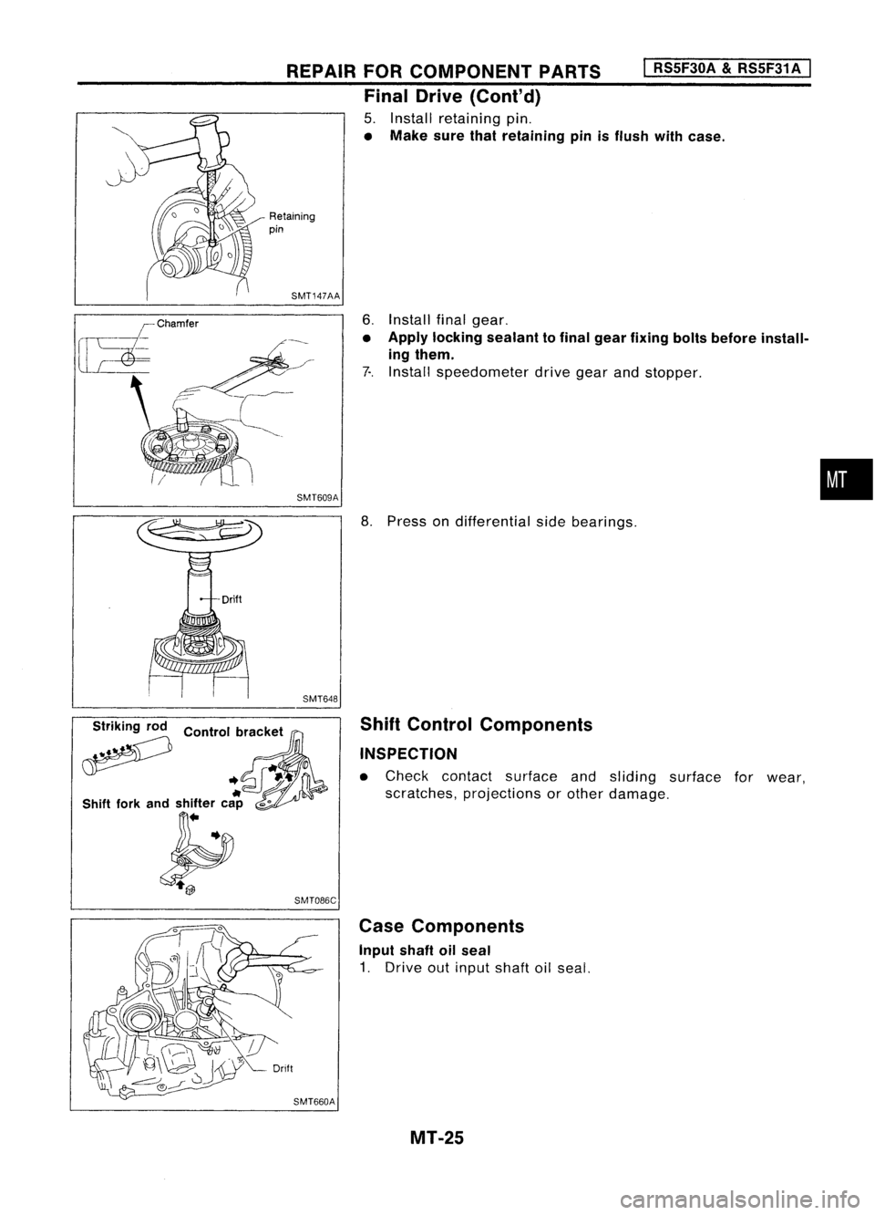
5. Install retaining pin.
• Make surethatretaining pinisflush withcase.
Retaining
pin
SMT147AA
6.Install finalgear.
• Apply locking sealant tofinal gear fixing boltsbefore install-
ing them.
7-. Install speedometer drivegearandstopper .
SMT609A
•
;?
Control
b~'Ck:t ,
.. ~-t'
If
0
Shift forkandshifter cap
",0
~ SMT086C
8.
Press ondifferential sidebearings.
Shift Control Components
INSPECTION
• Check contact surface andsliding surface forwear,
scratches, projections orother damage.
Case Components
Input shaftoilseal
1. Drive outinput shaftoilseal.
MT-25
Page 1568 of 1701
REPAIRFORCOMPONENT PARTS
Case Components (Cont'd)
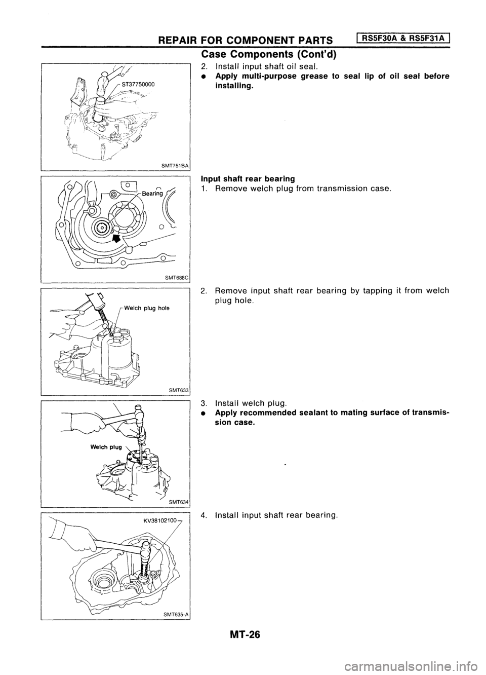
2. Install inputshaft oilseal.
• Apply multi-purpose greaseto
installing.
SMT751BA
I
RSSF30A
&
RSSF31A
I
seal lipofoil seal before
Input shaftrearbearing
1. Remove welchplugfrom transmission case.
SMT688C
2.Remove inputshaft rearbearing bytapping itfrom welch
plug hole.
r
Welch plughole
SMT633
3.Install welchplug.
• Apply recommended sealanttomating surface oftransmis-
sion case.
4. Install inputshaft rearbearing.
MT-26
Page 1569 of 1701
Toward
oil pocket
REPAIR
FORCOMPONENT PARTS
I
RS5F30A
&
RS5F31A
I
Case Components (Cont'd)
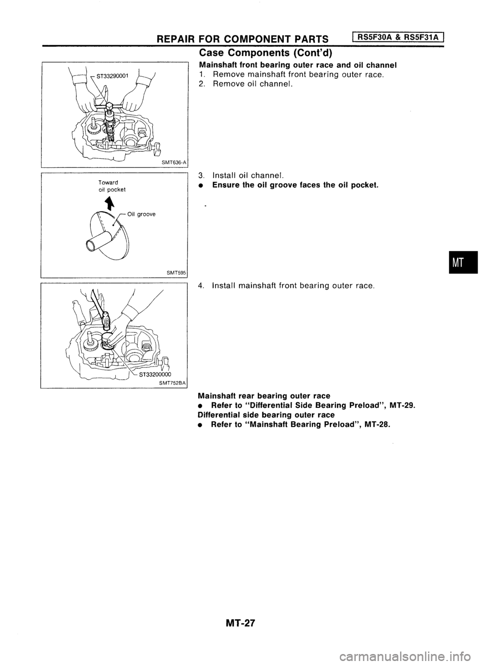
Mainshaft frontbearing outerraceandoilchannel
1. Remove mainshaft frontbearing outerrace.
2. Remove oilchannel.
SMT636-A
3.Install oilchannel.
• Ensure theoilgroove facestheoilpocket.
SMT595
•
4. Install mainshaft frontbearing outerrace.
Mainshaft rearbearing outerrace
• Refer to"Differential SideBearing Preload", MT-29.
Differential sidebearing outerrace
• Refer to"Mainshaft BearingPreload", MT-28.
MT-27
Page 1570 of 1701
ADJUSTMENT
I
RS5F30A
&
RS5F31 A
I
SMT646-A
I"
KV38106000
SMT454-ADifferential
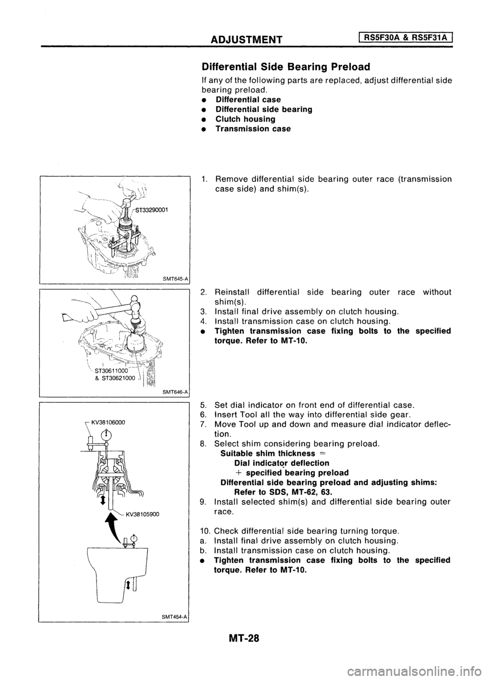
SideBearing Preload
If any ofthe following partsarereplaced, adjustdifferential side
bearing preload.
• Differential case
• Differential sidebearing
• Clutch housing
• Transmission case
1. Remove differential sidebearing outerrace(transmission
case side) andshim(s).
2. Reinstall differential sidebearing outerracewithout
shim(s).
3. Install finaldrive assembly onclutch housing.
4. Install transmission caseonclutch housing.
• Tighten transmission casefixing boltstothe specified
torque. RefertoMT-10.
5. Set dial indicator onfront endofdifferential case.
6. Insert Toolallthe way intodifferential sidegear.
7. Move Toolupand down andmeasure dialindicator deflec-
tion.
8. Select shimconsidering bearingpreload.
Suitable shimthickness =
Dial
indicat~r
deflection
+ specified bearingpreload
Differential sidebearing preload andadjusting shims:
Refer to50S, MT-62, 63.
9. Install selected shim(s)anddifferential sidebearing outer
race.
10. Check differential sidebearing turningtorque.
a. Install finaldrive assembly onclutch housing.
b. Install transmission caseonclutch housing.
• Tighten transmission casefixing boltstothe specified
torque. RefertoMT-10.
MT-28