NISSAN ALMERA N15 1995 Service Manual
Manufacturer: NISSAN, Model Year: 1995, Model line: ALMERA N15, Model: NISSAN ALMERA N15 1995Pages: 1701, PDF Size: 82.27 MB
Page 1541 of 1701
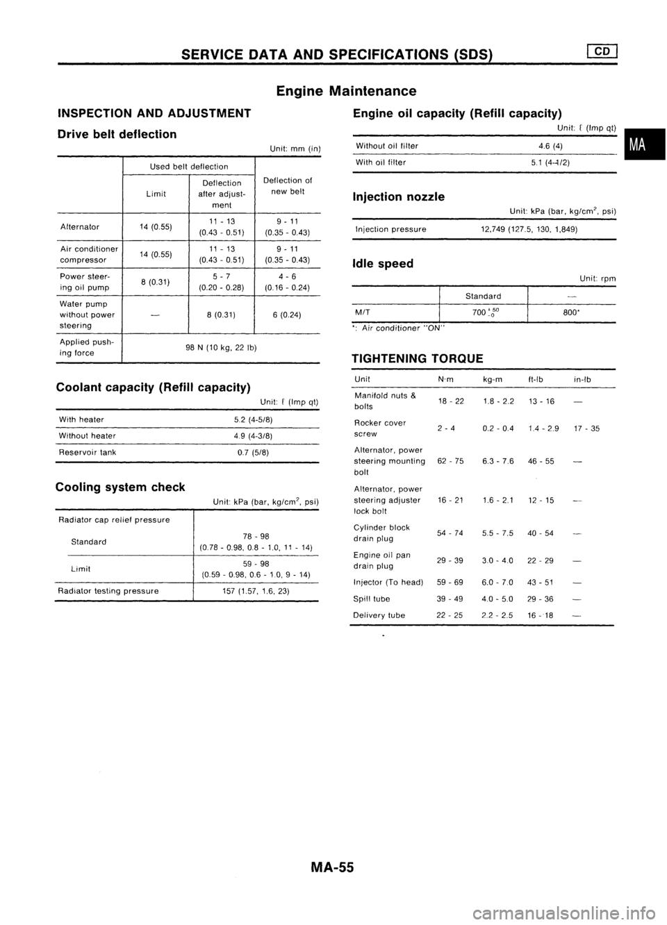
SERVICEDATAANDSPECIFICATIONS (50S)
Used beltdeflection
Deflection Deflection
of
Limit afteradjust- new
belt
ment
Alternator 14(055) 11
-13 9-11
(0.43 -0.51)
(0.35-0.43)
Air conditioner
14(0.55) 11
-13
9-11
compressor (0.43
-0.51)
(0.35-0.43)
Power steer-
8(0.31) 5
-7
4-6
ing oilpump (0.20-0.28)
(0.16-0.24)
Water pump
without power
-
8
(0.31) 6(0.24)
steering
Applied push-
98N(10 kg, 22Ib)
ing force
Coolant capacity (Refillcapacity)
INSPECTION
ANDADJUSTMENT
Drive beltdeflection
Unit:kPa(bar, kg/cm', psi)
12,749 (127.5, 130,1,849)
Without
oilfilter
With oilfilter
Injection pressure
Injection
nozzle
Idle speed
Unit:rpm
Standard
M/T
700
'go
800'
': Air conditioner "ON"
TIGHTENING TORQUE
Unit N'mkg-m
ft-Ib in-Ib
Manifold nuts
&
18-22
1.8-2.2
bolts 13
-16
Rocker cover
2-4
0.2-0.4 1.4-2.9 17-35
screw
Alternator, power
steering mounting 62-75
6.3-76 46
-55
bolt
Alternator, power
steering adjuster 16
-21
1.6-2.1
12-15
lock bolt
Cylinder block
54-74
5.5-7.5 40
-54
drain plug
Engine oilpan
29-39 3.0-4.0 22-29
drain plug
Injector (Tohead)
59-69 6.0-7.0 43-51
Spill tube 39-49
4.0-5.0 29-36
Delivery tube 22-25 2.2-2.5
16-18
Engine
Maintenance
Engine oilcapacity (Refillcapacity)
Unit:[(Imp qt)•
46 (4)
51 (4--1/2)
Unit:
mm(in)
Unit:
f
(Imp qt)
5.2 (4-5/8)
49 (4-3/8)
0.7 (5/8)
Unit: kPa(bar, kg/cm', psi)
78 -98
(0.78 -0.98, 08-1.0, 11-14)
59 -98
(0.59 -0.98, 06-10, 9-14)
157 (1.57, 1.6,23)
Standard
Limit
With
heater
Without heater
Reservoir tank
Radiator caprelief pressure
Radiator testingpressure
Cooling
systemcheck
MA-55
Page 1542 of 1701
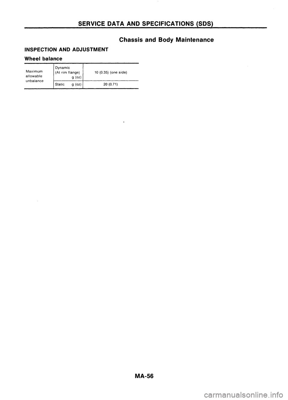
SERVICEDATAANDSPECIFICATIONS (50S)
Chassis andBody Maintenance
INSPECTION ANDADJUSTMENT
Wheel balance
Maximum
allowable unbalance Dynamic
(At
rim flange)
g(oz)
Static g(oz)
10
(0.35) (oneside)
20 (0.71)
MA-56
Page 1543 of 1701
MANUALTRANSAXLE
SECTION
MT
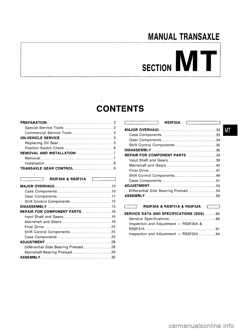
CONTENTS
PREPARATION 2
Special Service Tools 2
Commercial ServiceTools 4
ON-VEHICLE SERVICE
5
Replacing OilSeal 5
Position SwitchCheck 6
REMOVAL ANDINSTAllATION 7
Removal ,7
Installation '8
TRANSAXlE GEARCONTROL 9
RS5F30A
&
RS5F31 A
MAJOR OVERHAUL 10
Case Components 10
Gear Components ,11
Shift Control Components , 12
DiSASSEMBly ,13
REPAIR FORCOMPONENT PARTS 16
Input Shaft andGears 16
Mainshaft andGears 19
Final Drive ,,23
Shift Control Components 25
Case Components ,25
ADJUSTMENT ,,.. , 28
Differential SideBearing Preload 28
Mainshaft BearingPreload ,29
ASSEMBly ,30 RS5F32A
MAJOR OVERHAUl ,,,
33
Case Components , 33
Gear Components 34
Shift Control Components 35
DiSASSEMBly ",.,., , ,36
REPAIR FORCOMPONENT PARTS 39
Input Shaft andGears 39
Mainshaft andGears 42
Final Drive .47
Shift Control Components 49
Case Components ' 51
ADJUSTMENT ,, ", 54
Differential SideBearing Preload ,54
ASSEMBLY ',
56
'----_-JI RS5F30A
&
RS5F31A
&
RS5F32A
SERVICE DATAANDSPECIFICATIONS (SDS)60
General Specifications 60
Inspection andAdjustment -RS5F30A &
RS5F31 A ' 61
Inspection andAdjustment -RS5F32A 64
•
Page 1544 of 1701
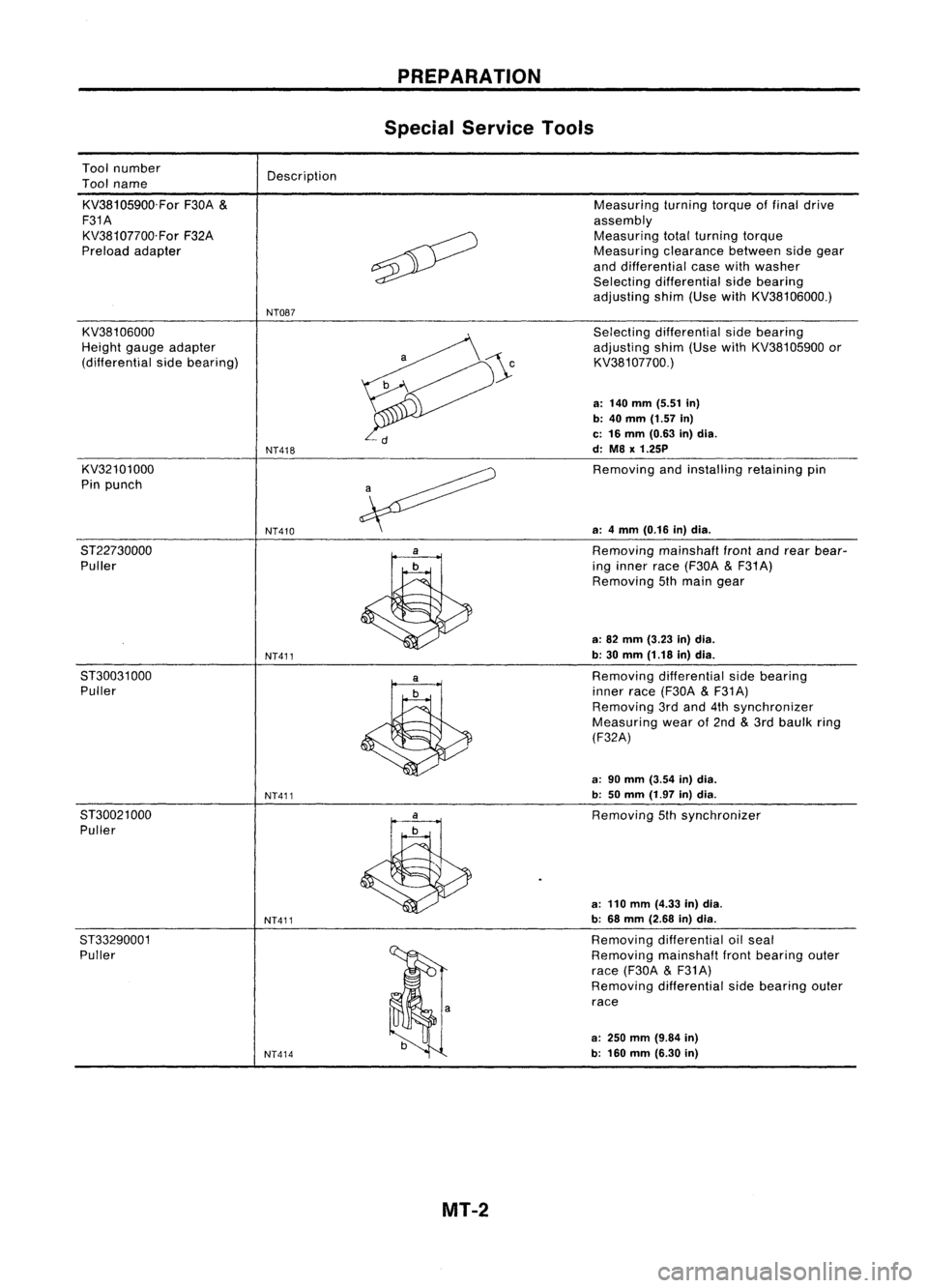
Toolnumber
Tool name
KV38105900.For F30A
&
F31A KV38107700.For F32A
Preload adapter Description
NT087 PREPARATION
Special Service Tools
Measuring turningtorqueoffinal drive
assembly Measuring totalturning torque
Measuring clearancebetweensidegear
and differential casewithwasher
Selecting differential sidebearing
adjusting shim(UsewithKV38106000.)
KV38106000
Height gaugeadapter
(differential sidebearing)
KV32101000
Pin punch
8T22730000 Puller
8T30031 000
Puller
8T30021 000
Puller
ST33290001 Puller
NT418
NT410
NT411
NT411
NT411
NT414
Selecting
differential sidebearing
adjusting shim(UsewithKV38105900 or
KV381 07700.)
a: 140 mm (5.51 in)
b: 40
mm
(1.57
in)
c: 16 mm (0.63 in)dia.
d: M8
x
1.25P
Removing andinstalling retainingpin
a: 4mm (0.16 in)dia.
Removing mainshafl
front
andrear bear-
ing inner race(F30A
&
F31 A)
Removing 5thmain gear
a: 82 mm (3.23 in)dia.
b: 30 mm (1.18 in)dia.
Removing differential sidebearing
inner race(F30A
&
F31A)
Removing 3rdand 4thsynchronizer
Measuring wearof2nd
&
3rd baulk ring
(F32A)
a: 90 mm (3.54 in)dia.
b: 50mm (1.97 in)dia.
Removing 5thsynchronizer
a: 110 mm (4.33 in)dia.
b: 68 mm (2.68 in)dia.
Removing differential oilseal
Removing mainshaflfrontbearing outer
race (F30A
&
F31A)
Removing differential sidebearing outer
race
a:
250
mm
(9.84
in)
b: 160 mm (6.30 in)
MT-2
Page 1545 of 1701
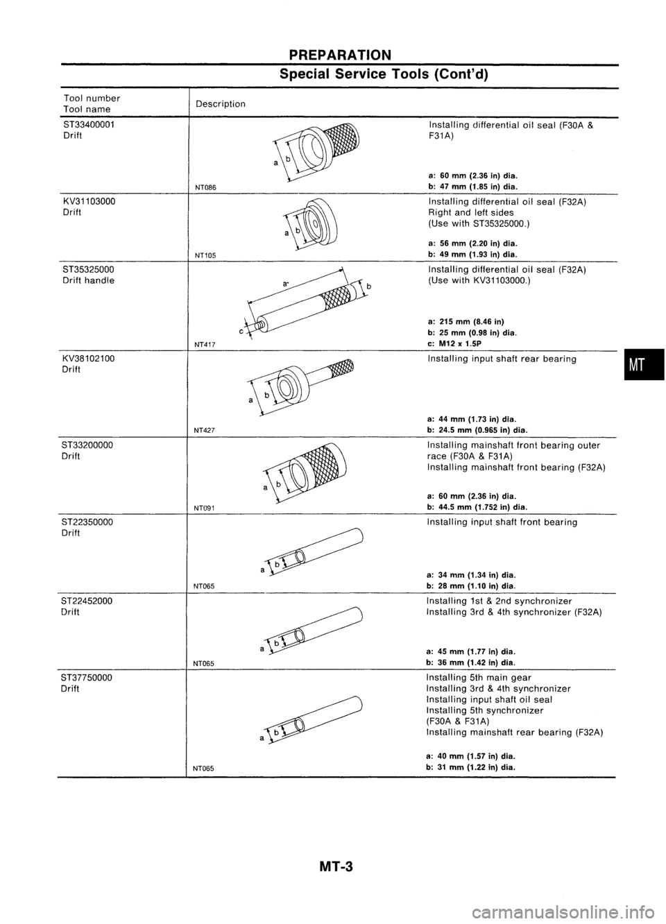
PREPARATION
Special Service Tools(Coni'd)
a-
Tool
number
Tool name
ST33400001 Drift
KV31103000
Drift
ST35325000 Drift handle
KV38102100
Drift Description
NT086
NT105
c
NT417
Installing
differential oilseal (F30A
&
F31A)
a: 60 mm (2.36 in)dia.
b: 47 mm (1.85 in)dia.
Installing differential oilseal (F32A)
Right andleftsides
(Use withST35325000.)
a: 56 mm (2.20 in)dia.
b: 49 mm (1.93 in)dia.
Installing differential oilseal (F32A)
(Use withKV31103000.)
a: 215 mm (8.46 in)
b: 25 mm (0.98 in)dia.
c: M12 x1.5P
Installing inputshaft rearbearing
•
a: 44 mm (1.73 in)dia.
NT427
b:24.5 mm(0.965 in)dia.
ST33200000 Installingmainshaft frontbearing outer
Drift race(F30A
&
F31A)
Installing mainshaft frontbearing (F32A)
a: 60 mm (2.36 in)dia.
NT091
b:
44.5 mm(1.752 in)dia.
ST22350000 Installinginputshaft frontbearing
Drift
a
a:34 mm (1.34 in)dia.
NT065
b:28 mm (1.10 in)dia.
ST22452000 Installing1st
&
2nd synchronizer
Drift Installing3rd
&
4th synchronizer (F32A)
a
a:45 mm (1.77 in)dia.
NT065
b:
36 mm (1.42 in)dia.
ST37750000 Installing5thmain gear
Drift Installing
3rd
&
4th synchronizer
Installing inputshaft oilseal
Installing 5thsynchronizer
(F30A
&
F31A)
a
Install
ingmainshaft rearbearing (F32A)
a: 40 mm (1.57 in)dia.
NT065
b:
31 mm (1.22 in)dia.
MT-3
Page 1546 of 1701
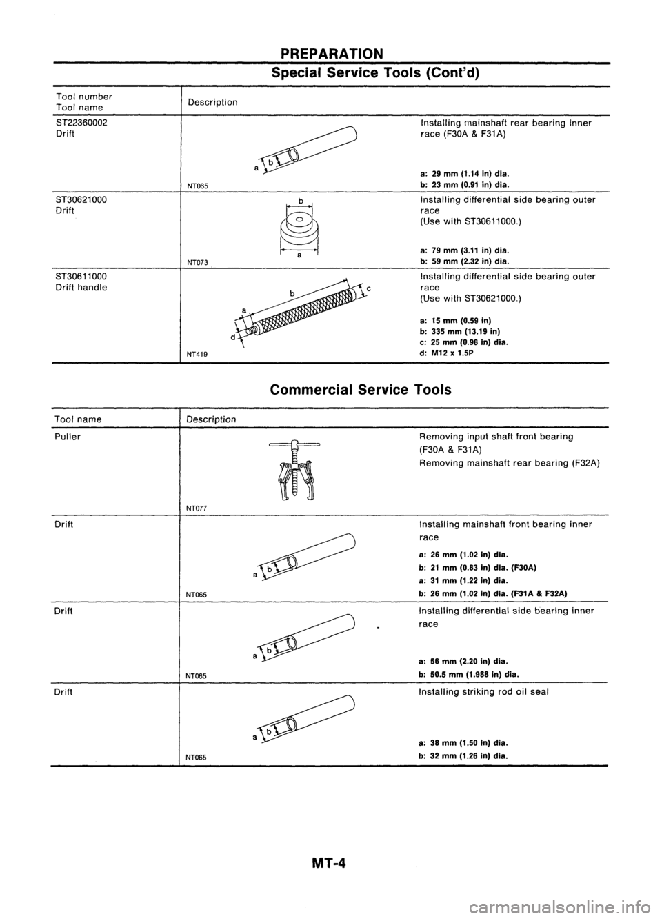
PREPARATION
Special Service Tools(Coni'd)
Tool number
Tool name
ST22360002 Drift
ST30621000 Drift
ST30611000 Drift handle Description
NT065
NT073
NT419 a
~a
Installing
rnainshaft rearbearing inner
race (F30A
&
F31A)
a:
29
mm
(1.14
in)dia.
b: 23 mm (0.91 in)dia.
Installing differential sidebearing outer
race
(Use withST30611000.)
a: 79 mm (3.11 in)dia.
b: 59mm (2.32 in)dia.
Installing differential sidebearing outer
race
(Use withST30621000.)
a: 15mm (0.59 in)
b: 335 mm (13.19 in)
c: 25 mm (0.98 In)dia.
d: M12 x1.5P
Commercial ServiceTools
Tool name
Description
Puller
m:
o
0
NT077
Drift
Drift
Drift
NT065
NT065
NT065 a
Removing
inputshaft frontbearing
(F30A
&
F31A)
Removing mainshaftrearbearing (F32A)
Installing mainshaft frontbearing inner
race
a: 26mm (1.02 in)dia.
b: 21mm (0.83 in)dia. (F30A)
a: 31mm (1.22 in)dia.
b: 26 mm (1.02 in)dia. (F31A
&
F32A)
Installing differential sidebearing inner
race
a: 56mm (2.20 In)dia.
b: 50.5 mm(1.988 in)dia.
Installing strikingrodoilseal
a: 38 mm (1.50 In)dia.
b: 32 mm (1.26 in)dla.
MT-4
Page 1547 of 1701
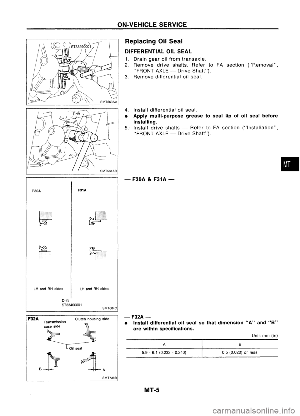
ON-VEHICLESERVICE
Replacing OilSeal
DIFFERENTIAL OILSEAL
1. Drain gearoilfrom transaxle.
2. Remove driveshafts. RefertoFA section ("Removal",
"FRONT AXLE-Drive Shaft").
3. Remove differential oilseal.
4. Install differential oilseal.
• Apply multi-purpose greasetoseal lipofoil seal before
installing.
5.- Install driveshafts -Refer toFA section ("Installation",
"FRONT AXLE-Drive Shaft").
- F30A
&
F31A-
•
F30A F31A
LH and RHsides LHand RHsides
Drift
ST33400001
SMT684C
.P
-F32A
-
• Install differential oilseal sothat dimension "A"and"B"
are within specifications.
F32A
Transmission
case side Clutch
housing side
Oil seal
SMT7388
A
5.9 -6.1 (0.232 -0.240)
MT-5
Unit:
mm(in)
B
0.5 (0.020)
or
less
Page 1548 of 1701
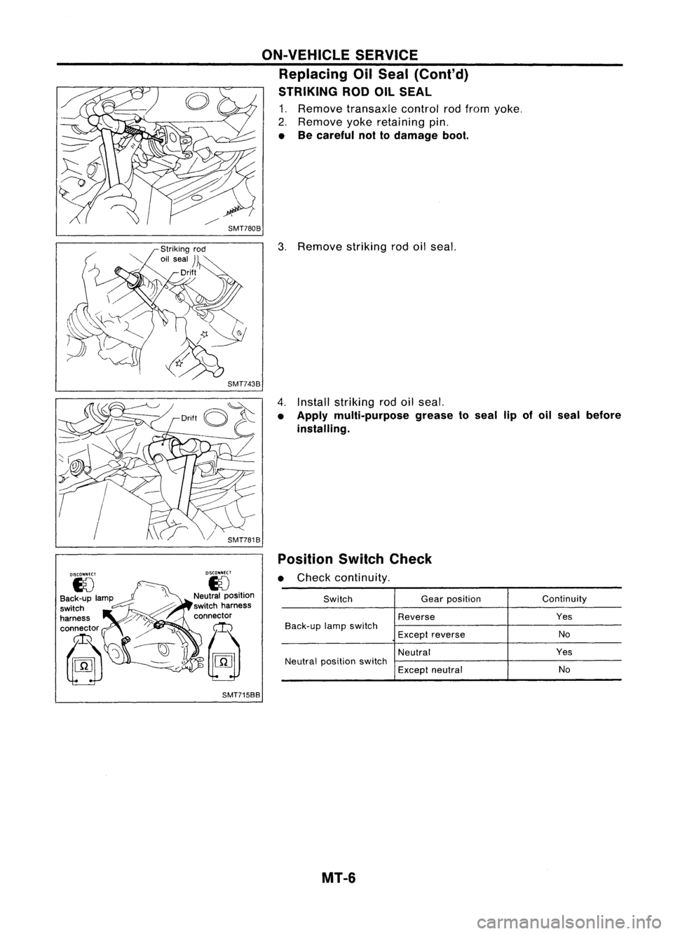
SwitchGearposition Continuity
Reverse Yes
Back-up lampswitch
No
Except reverse
Neutral Yes
Neutral position switch
Exceptneutral No
3.
Remove strikingrodoilseal.
Position SwitchCheck
• Check continuity.
4.
Install striking rodoilseal.
• Apply multi-purpose greasetoseal lipofoil seal before
installing.
ON-VEHICLE
SERVICE
Replacing OilSeal (Cont'd)
STRIKING RODOILSEAL
1. Remove transaxle controlrodfrom yoke.
2. Remove yokeretaining pin.
• Becareful nottodamage boot.
DISCONNECT
eJ
Neutral position
switch harness
connector
~ SMT715BB
MT-6
Page 1549 of 1701
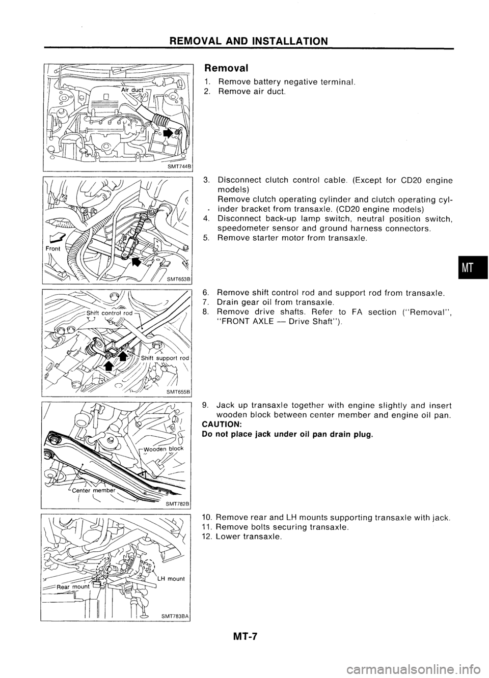
REMOVALANDINSTALLATION
Removal
1. Remove batterynegative terminal.
2. Remove airduct.
3. Disconnect clutchcontrol cable.(Except forCD20 engine
models)
Remove clutchoperating cylinderandclutch operating cyl-
inder bracket fromtransaxle. (CD20engine models)
4. Disconnect back-uplampswitch, neutralposition switch,
speedometer sensorandground harness connectors.
5. Remove startermotorfromtransaxle.
6. Remove shiftcontrol rodand support rodfrom transaxle.
7. Drain gearoilfrom transaxle.
8. Remove driveshafts. RefertoFA section ("Removal",
"FRONT AXLE-Drive Shaft").
9. Jack uptransaxle togetherwithengine slightly andinsert
wooden blockbetween centermember andengine oilpan.
CAUTION:
Do not place jackunder oilpan drain plug.
10. Remove rearandLHmounts supporting transaxlewithjack.
11. Remove boltssecuring transaxle.
12. Lower transaxle.
MT-7
•
Page 1550 of 1701
@
M/T
toengine
CD
REMOVAL
ANDINSTAllATION
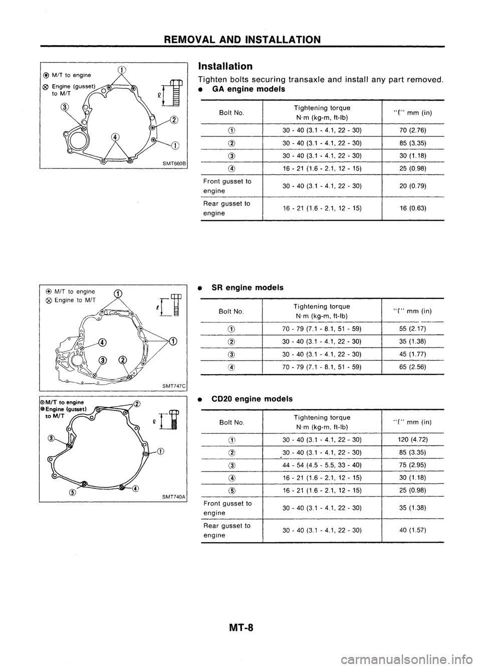
Installation
Tighten boltssecuring transaxle andinstall anypart removed.
• GA engine models
Bolt No. Tightening
torque
"C"mm (in)
N'm (kg-m, ft-Ib)
G) 30-40 (3.1 -4.1,22 -30) 70
(2.76)
@ 30-40 (3.1 -4.1,22 -30) 85(3.35)
@
30-40 (3.1 -4.1, 22-30) 30(1.18)
@ 16-21 (1.6 -2.1,12 -15) 25(0.98)
Front gusset to
30-40 (3.1 -4.1,22 -30) 20(0.79)
engine
Rear gusset to
16-21 (1.6 -2.1,12 -15) 16
(0.63)
engine
@
M/T
toengine ~
Q9
Engine toM/T
leV
~o". Q~.\
17
SMT747C
CD
SMT740A •
SRengine models
Bolt No. Tightening
torque
"C"mm (in)
N'm (kg-m, ft-Ib)
--
G)
70-79 (7.1 -8.1,51 -59) 55
(2.17)
@
30-40 (3.1 -4.1,22 -30) 35
(1.38)
@
30-40 (3.1 -4.1,22 -30) 45
(1.77)
@ 70-79 (7.1 -8.1,51 -59) 65
(2.56)
• CD20 engine models
Boll No. Tightening
torque
"C"mm (in)
N'm (kg-m, ft-Ib)
G)
30
-40 (3.1 -4.1, 22-30) 120
(4.72)
@
30-40 (3.1 -4.1,22 -30) 85
(3.35)
@
44
-54 (4.5 -5.5, 33-40) 75
(2.95)
@
16-21 (1.6 -2.1,12 -15) 30
(1.18)
@
16-21 (1.6 -2.1,12 -15) 25
(0.98)
Front gusset to
30-40 (3.1 -4.1, 22-30) 35
(1.38)
engine
Rear gusset to
30-40 (3.1 -4.1, 22-30) 40
(1.57)
engine
MT-8