NISSAN ALMERA N15 1995 Service Manual
Manufacturer: NISSAN, Model Year: 1995, Model line: ALMERA N15, Model: NISSAN ALMERA N15 1995Pages: 1701, PDF Size: 82.27 MB
Page 1571 of 1701
~casecover"U--0-ring
~spacer
Mainshaft rearbearing ~ Mainshaft
outer race ~
0
bearing
- \ adjusting
shim
I ~--
SMT613AA
SMT599 ADJUSTMENT
I
RS5F30A
&
RS5F31A
I
Differential SideBearing Preload(Cont'd)
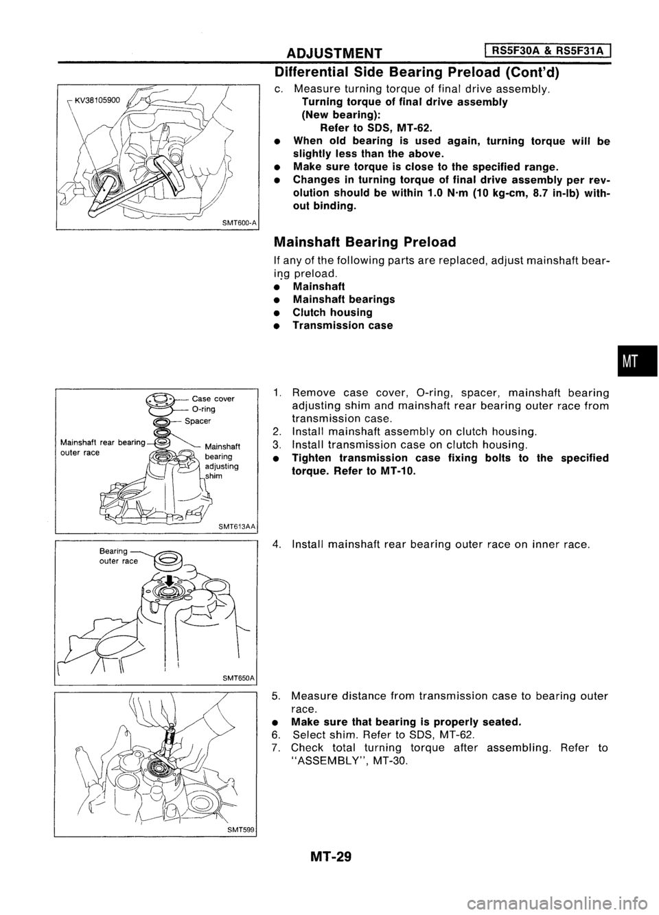
c. Measure turningtorqueoffinal drive assembly.
Turning torqueoffinal drive assembly
(New bearing):
Refer toSOS, MT-62.
• When oldbearing isused again, turning torquewillbe
slightly lessthan theabove.
• Make suretorque isclose tothe specified range.
• Changes inturning torqueoffinal drive assembly perrev-
olution shouldbewithin 1.0N'm (10kg-em, 8.7in-Ib) with-
out binding.
Mainshaft BearingPreload
If any ofthe following partsarereplaced, adjustmainshaft bear-
il}g preload.
• Mainshaft
• Mainshaft bearings
• Clutch housing
• Transmission case
1. Remove casecover, O-ring, spacer, mainshaft bearing
adjusting shimandmainshaft rearbearing outerracefrom
transmission case.
2. Install mainshaft assemblyonclutch housing.
3. Install transmission caseonclutch housing.
• Tighten transmission casefixing boltstothe specified
torque. RefertoMT-10.
4. Install mainshaft rearbearing outerraceoninner race.
5. Measure distancefromtransmission casetobearing outer
race.
• Make surethatbearing isproperly seated.
6. Select shim.RefertoSDS, MT-62.
7. Check totalturning torqueafterassembling. Referto
"ASSEMBLY", MT-30.
MT-29
•
Page 1572 of 1701
ASSEMBLY
I
RS5F30A &RS5F31 A
I
SMT648AA
1.
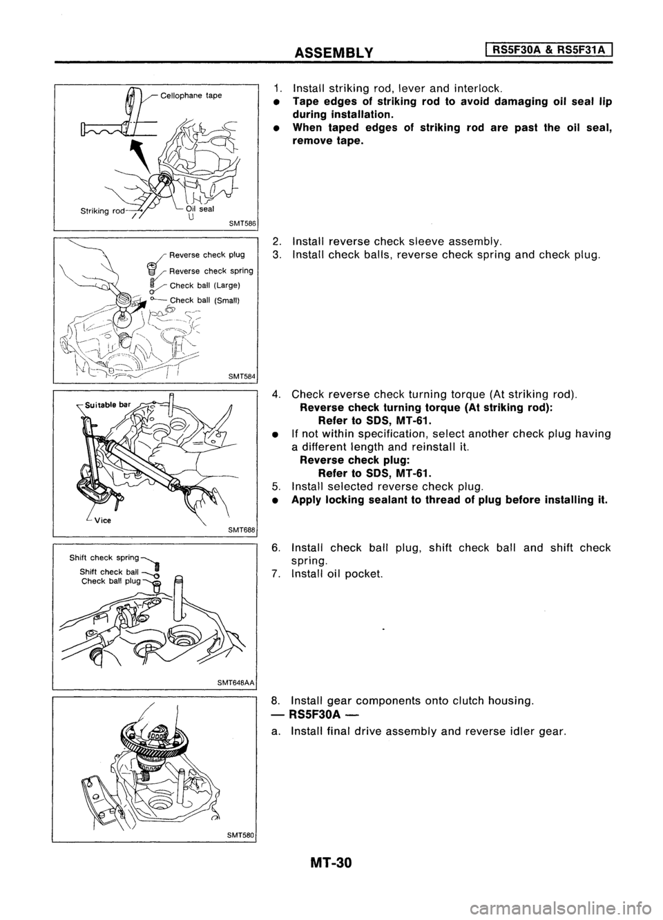
Install striking rod,lever andinterlock.
• Tape edges ofstriking rodtoavoid damaging oilseal lip
during installation.
• When taped edges ofstriking rodare past theoilseal,
remove tape.
2. Install reverse checksleeve assembly.
3. Install check balls,reverse checkspring andcheck plug.
4. Check reverse checkturning torque(Atstriking rod).
Reverse checkturning torque(Atstriking rod):
Refer toSOS, MT-61.
• Ifnot within specification, selectanother checkplughaving
a different lengthandreinstall it.
Reverse checkplug:
Refer toSOS, MT-61.
5. Install selected reversecheckplug.
• Apply locking sealanttothread ofplug before installing it.
6. Install check ballplug, shiftcheck balland shift check
spring.
7. Install oilpocket.
SMT580
8.
Install gearcomponents ontoclutch housing.
- RS5F30A-
a. Install finaldrive assembly andreverse idlergear.
MT-30
Page 1573 of 1701
ASSEMBLY
I
RS5F30A
&
RS5F31 A
I
Suitable
tool
SMT737A
SMT664
~ "--Soft hammer
SMT614A
Final driveassembly
/{(/
SMT721
b.
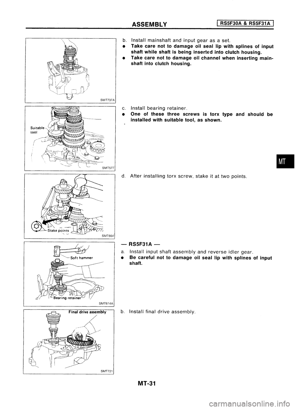
Install mainshaft andinput gearasaset.
• Take carenottodamage oilseal lipwith splines ofinput
shaft while shaftisbeing inserted intoclutch housing.
• Take carenottodamage oilchannel wheninserting main-
shaft intoclutch housing.
c. Install bearing retainer.
• One ofthese threescrews istorx type andshould be
installed withsuitable tool,asshown.
d. After installing torxscrew, stakeitat two points.
- RS5F31A-
a. Install inputshaft assembly andreverse idlergear.
• Becareful nottodamage oilseal lipwith splines ofinput
shaft.
b. Install finaldrive assembly.
MT-31
•
Page 1574 of 1701
ASSEMBLYI
RSSF30A
&
RSSF31 A
I
SMT720
c.
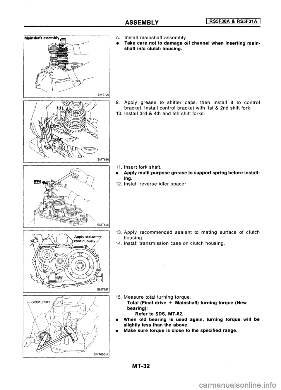
Install mainshaft assembly.
• Take carenottodamage oilchannel wheninserting main-
shaft intoclutch housing.
9. Apply grease toshifter caps,theninstall itto control
bracket. Installcontrol bracket with1st
&
2nd shift fork.
10. Install 3rd
&
4th and 5thshift forks.
11. Insert forkshaft.
• Apply multi-purpose greasetosupport springbefore install-
ing.
12. Install reverse idlerspacer.
13. Apply recommended sealanttomating surface ofclutch
housing.
14. Install transmission caseonclutch housing.
15. Measure totalturning torque.
Total (Final drive+Mainshaft) turningtorque(New
bearing): Refer toSOS, MT-62.
• When oldbearing isused again, turning torquewillbe
slightly lessthan theabove.
• Make suretorque isclose tothe specified range.
MT-32
Page 1575 of 1701
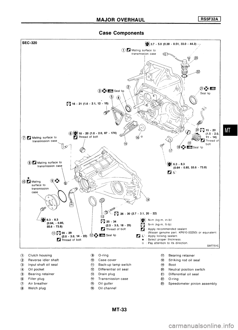
MAJOROVERHAUL
I
RS5F32A
I
Case Components
•
\
\L~
6.3.8.3
(0.64 -0.85, 55.6-73.8)
~.L'
J
(15,'
~
3.7•5.0 (0.38 •0.51, 33.0-44.3)
CD ~
Mating surface to
transmission case~
I
;1
~3J
1J2»~
o//~
d~~~
!-~~
i~=1D.
(]?
CID.:.
m
Seal lip \
\
.
~)~
//\
1~
~'
(fl)
to.J
20-29 \
- (2.0-3.0, 14-22)
~ Thread ofbolt
@
~
Mating surface to
SEC.320
@~
10.20 (1.0-2.0, 87-174)
W ~
Mating surface to ~Thread ofbolt
"""mi"ioo '""
\1:.0
1 ~ /',
. WO,,~., .,.~
~~~> '\
t,,~~~~
o
I:::t:\ ~___-- __~
j)\~
~i)~/
(ro\~\~)
. ------ ~~,/ ~Q~
I
f""\
~~~ ..~ Q{
t~A
26-30 (2.7 -3.1, 20-22)
!13i
~ 25_34 ~N.m(kg-m, In-Ib\
(2.5 -3.5, 18-25)
A
N.m(kg-m, ft-Ib)
~ Thread ofbolt ~.Apply recommended sealant
(Nissan genuine part:KP610-00250) orequivalent
12)~.
m
Seal lip ~
,.1..',
Apply locking sealant
* :
Select proper thickness.
-tI .
Pay attention toits direction,
*
@~Mating
SMT751C
G)
Clutch housing
@
Reverse idlershaft
@
Input shaftoilseal
@
Oilpocket
@
Bearing retainer
@
Filler plug
(J)
Airbreather
@
Welch plug
(9)
O-ring
@
Case cover
CfD
Back-up lampswitch
@
Differential oilseal
@
Drain plug
@
Transmission case
@
Oilgutter
@
Oilchannel
@
Bearing retainer
@l
Striking rodoilseal
QID
Boot
@
Neutral position switch
@
Differential oilseal
@
O-ring
@
Speedometer pinionassembly
MT-33
Page 1576 of 1701
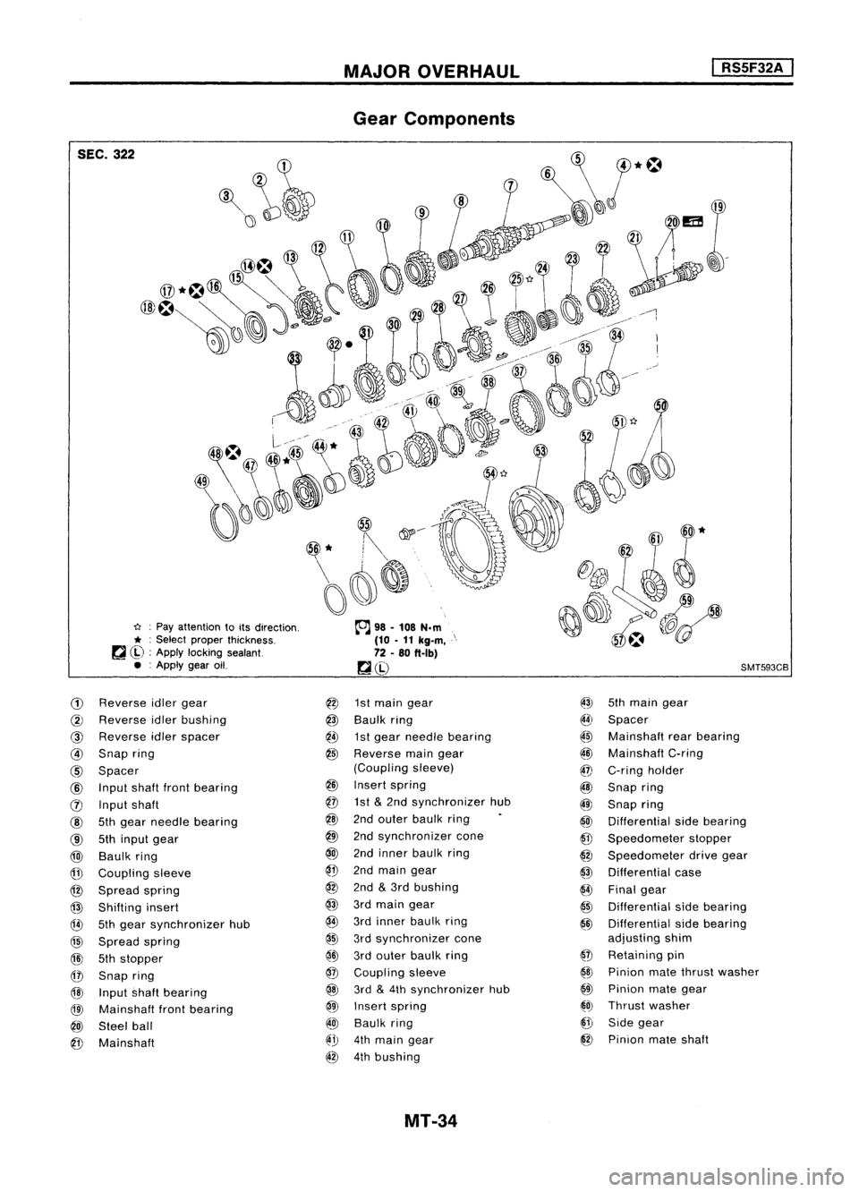
SEC.322
u:Pay attention toits direction.
* :
Select proper thickness.
~ ~) :Apply locking sealant.
• :Apply gearoil.
CD
Reverse idlergear
@
Reverse idlerbushing
@
Reverse idlerspacer
@
Snap ring
@
Spacer
@
Input shaftfrontbearing
(j) Input shaft
@
5thgear needle bearing
@
5thinput gear
@)
Baulk ring
@
Coupling sleeve
@
Spread spring
@
Shifting insert
@
5thgear synchronizer hub
@
Spread spring
@l
5thstopper
@
Snap ring
@
Input shaftbearing
@l
Mainshaft frontbearing
@)
Steel ball
@
Mainshaft
MAJOR
OVERHAUL
Gear Components
@
1stmain gear
@
Baulk ring
@
1stgear needle bearing
@
Reverse maingear
(Coupling sleeve)
@
Insert spring
@
1st
&
2nd synchronizer hub
@
2ndouter baulk ring
@
2ndsynchronizer cone
@
2ndinner baulk ring
@
2ndmain gear
@
2nd
&
3rd bushing
@
3rdmain gear
@
3rdinner baulk ring
@
3rdsynchronizer cone
@ID
3rdouter baulk ring
@
Coupling sleeve
@
3rd
&
4th synchronizer hub
@
Insert spring
@
Baulk ring
@".!J
4thmain gear
@
4thbushing
MT-34
I
RS5F32A
I
SMT593CB
@
5thmain gear
I[~
Spacer
~~ Mainshaft rearbearing
~ID
Mainshaft C-ring
@
C-ring holder
@
Snap ring
@
Snap ring
@
Differential sidebearing
@
Speedometer stopper
@
Speedometer drivegear
@
Differential case
{4)
Final gear
@
Differential sidebearing
@
Differential sidebearing
adjusting shim
@
Retaining pin
@
Pinion matethrust washer
@
Pinion mategear
~O)
Thrust washer
@
Side gear
@
Pinion mateshaft
Page 1577 of 1701
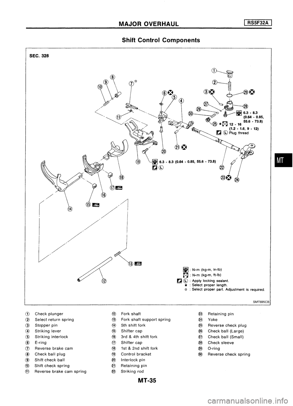
SEC.328 MAJOR
OVERHAUL
Shift Control Components
I
RSSF32A
I
/
r
~~
CV-~
~
CID~
6~~
~~
~ ~lil6.3-8.3
~ (0.64•0.85,
5 ~
55.6•73.8)
*~- ...12 -16
(1.2 -1.6, 9-12)
~ Cbl
Plug thread
/~
I
I
J
"@lEa!
lil:
N.m(kg-m, in-Ib)
~ :N.m (kg-m, ft-Ib)
~ Cbl :
Apply locking sealant.
* :
Select proper length.
~ :Select proper part.Adjustment isrequired.
SMT695CB
•
CD
Check plunger
@
Select returnspring
@
Stopper pin
@
Striking lever
@
Striking interlock
@
E-ring
(J)
Reverse brakecam
@
Check ballplug
@
Shift check ball
@)
Shift check spring
@
Reverse brakecamspring
@
Fork shaft
@
Fork shaft support spring
@
5thshift fork
@
Shifter cap
@
3rd
&
4th shift fork
@
Shifter cap
@
1st
&
2nd shift fork
@
Control bracket
@J
Interlock pin
@
Retaining pin
@
Striking rod
MT-35
@
Retaining pin
@
Yoke
@
Reverse checkplug
@
Check ball(Large)
@
Check ball(Small)
@
Check sleeve
@
O-ring
@
Reverse checkspring
Page 1578 of 1701
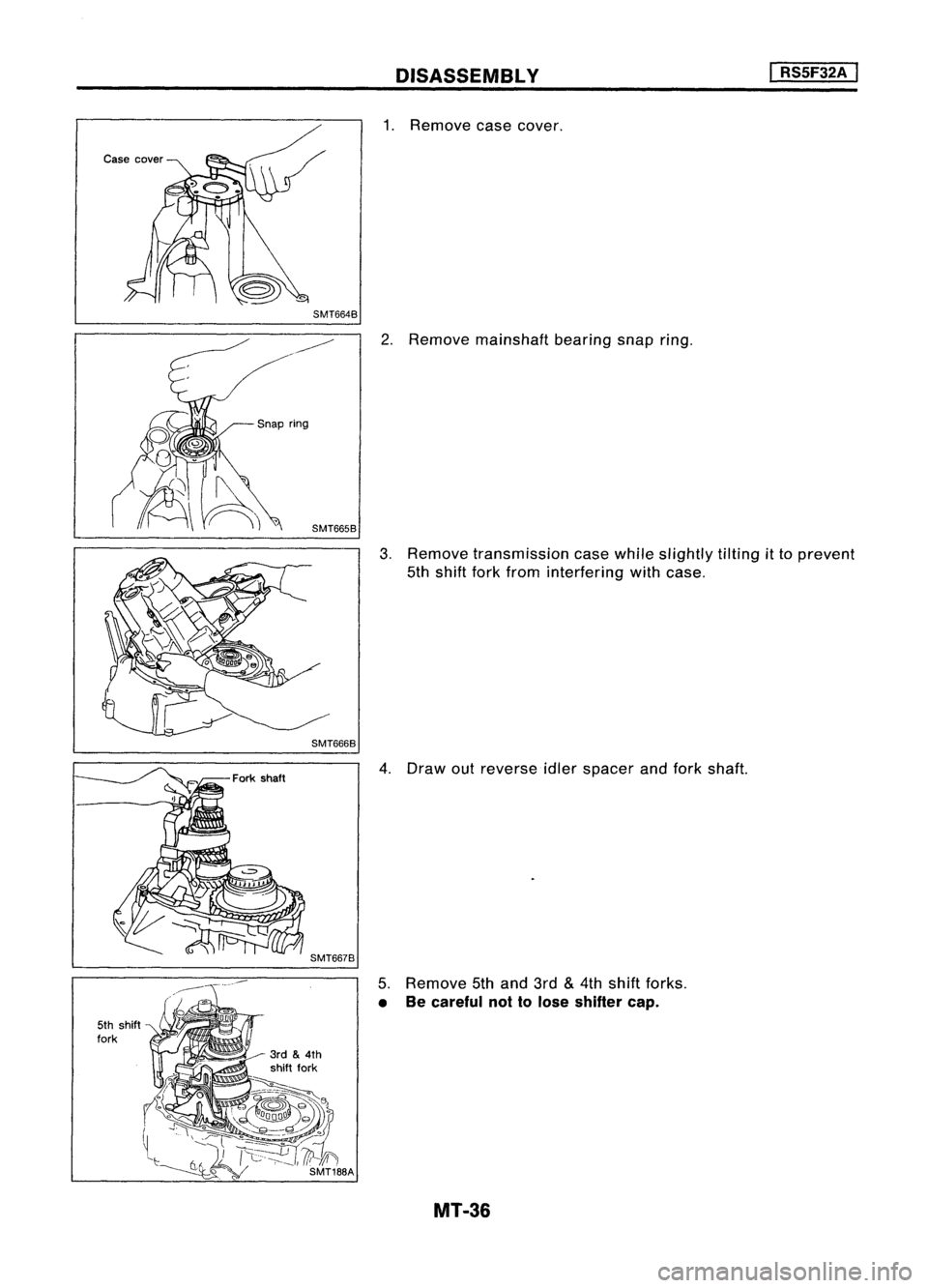
SMT6648DISASSEMBL
Y
1. Remove casecover.
I
RS5F32A
I
SMT6668
2.
Remove mainshaft bearingsnapring.
3. Remove transmission casewhile slightly tilting
it
to prevent
5th shift forkfrom interfering withcase.
5th shift
fork SMT6678
4.
Draw outreverse idlerspacer andfork shaft.
5. Remove 5thand 3rd
&
4th shift forks.
• Becareful nottolose shifter cap.
MT-36
Page 1579 of 1701
DISASSEMBlY
I
RS5F32A
I
SMT6708
SMT6718
SMT64BAA
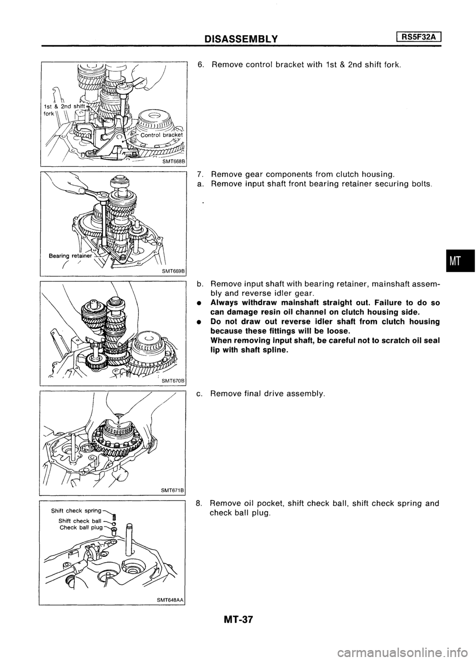
6.
Remove controlbracket with1st
&
2nd shift fork.
7. Remove gearcomponents fromclutch housing.
a. Remove inputshaftfrontbearing retainer securing bolts.
b. Remove inputshaftwithbearing retainer, mainshaft assem-
bly and reverse idlergear.
• Always withdraw mainshaft straightout.Failure todo so
can damage resinoilchannel onclutch housing side.
• Do not draw outreverse idlershaft fromclutch housing
because thesefittings willbeloose.
When removing inputshaft, becareful nottoscratch oilseal
lip with shaft spline.
c. Remove finaldrive assembly.
8. Remove oilpocket, shiftcheck ball,shiftcheck spring and
check ballplug.
MT-37
•
Page 1580 of 1701
DISASSEMBLV
I
RS5F32A
I
SMT599AA SMT583
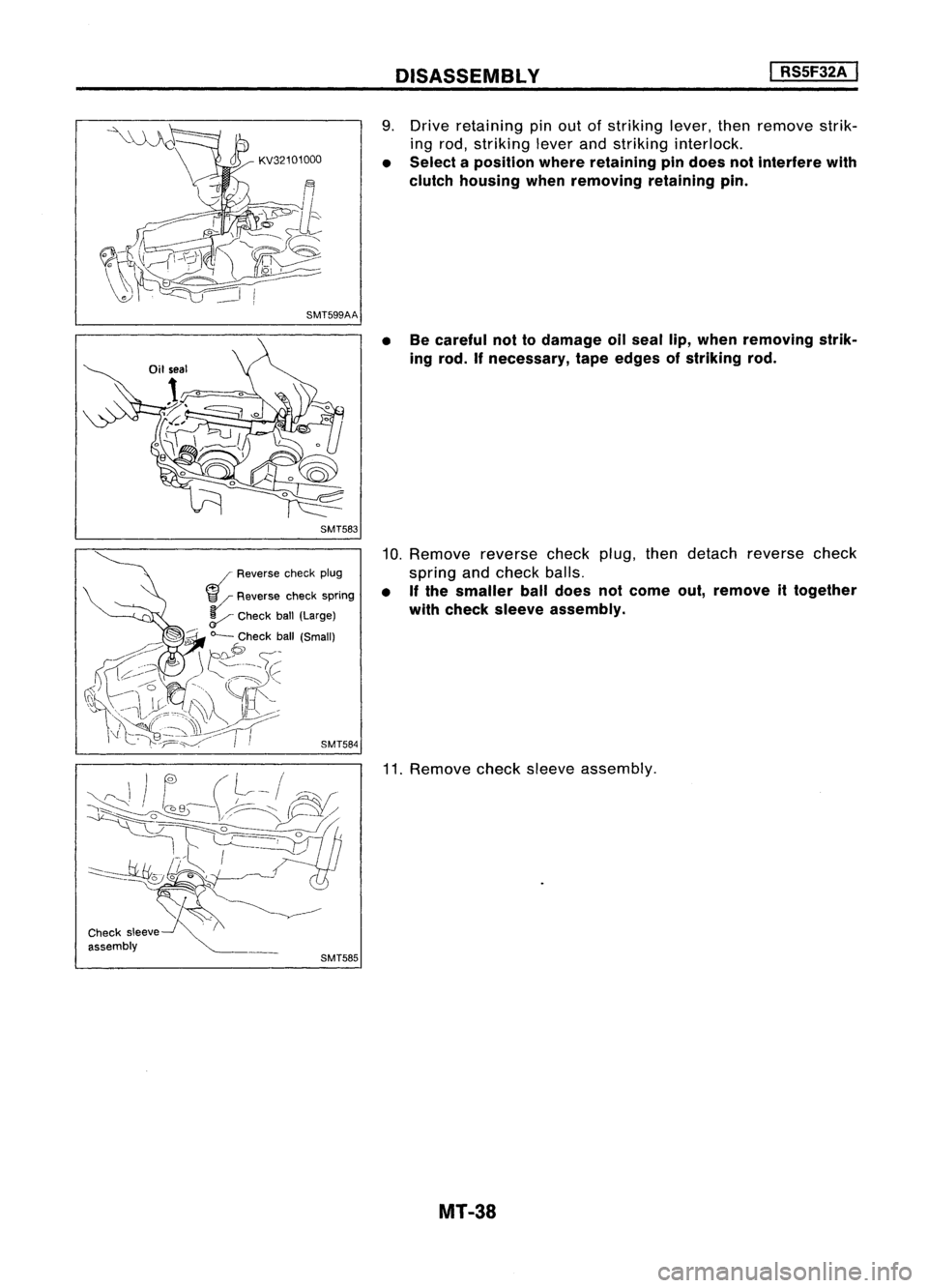
9.
Drive retaining pinout ofstriking lever,thenremove strik-
ing rod, striking leverandstriking interlock.
• Select aposition whereretaining pindoes notinterfere with
clutch housing whenremoving retainingpin.
• Becareful nottodamage oilseal lip,when removing strik-
ing rod. Ifnecessary, tapeedges ofstriking rod.
10. Remove reversecheckplug,thendetach reverse check
spring andcheck balls.
• Ifthe smaller balldoes notcome out,remove ittogether
with check sleeve assembly.
Check sleeve
assembly SMT585
11.
Remove checksleeve assembly.
MT-38