NISSAN ALMERA N15 1995 Service Manual
ALMERA N15 1995
NISSAN
NISSAN
https://www.carmanualsonline.info/img/5/57349/w960_57349-0.png
NISSAN ALMERA N15 1995 Service Manual
Trending: maintenance schedule, EC-301, brake light, Color, battery replacement, recommended oil, fog light bulb
Page 1591 of 1701
REPAIRFORCOMPONENT PARTS
I
RS5F32A
I
Final Drive (Cont'd)
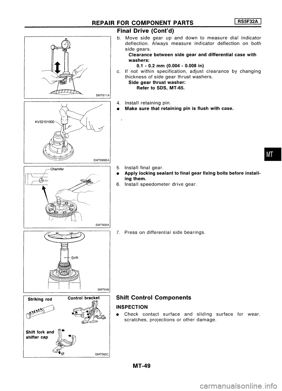
b. Move sidegear upand down tomeasure dialindicator
deflection. Alwaysmeasure indicatordeflection onboth
side gears.
Clearance betweensidegear anddifferential casewith
washers:
0.1 -0.2
mm
(0.004 -0.008
in)
c.
If
not within specification, adjustclearance bychanging
thickness ofside gear thrust washers.
Side gear thrust washer:
Refer toSOS, MT-65.
SMT611A
4.Install retaining pin.
• Make surethatretaining pinisflush withcase.
5. Install finalgear.
• Apply locking sealant tofinal gear fixing boltsbefore install-
ing them.
6. Install speedometer drivegear.
SMT609A
•
Striking rod
_.~0
~ SMT648
Control bracket
.~
7.
Press ondifferential sidebearings.
Shift Control Components
INSPECTION
• Check contact surface andsliding surface forwear,
scratches, projections orother damage.
Shift forkan};Jd"
shifter cap •
s:;
'l@
SMT093C
MT-49
Page 1592 of 1701
Strikinglever
Reverse brakeearn REPAIR
FORCOMPONENT PARTS
Shift Control Components (Cont'd)
SMT099C I
RS5F32A
I
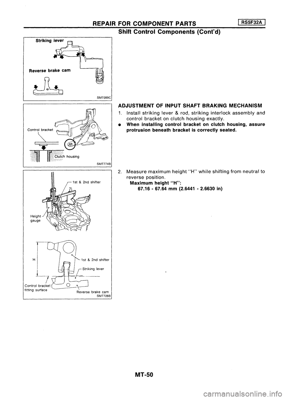
ADJUSTMENT OFINPUT SHAFT BRAKING MECHANISM
1. Install striking lever
&
rod, striking interlock assembly and
control bracket onclutch housing exactly.
• When installing controlbracket onclutch housing, assure
protrusion beneathbracketiscorrectly seated.
SMT774B
Height
gauge
2.
Measure maximum height"H"while shifting fromneutral to
reverse position.
Maximum height
"H":
67.16 -67.64
mm
(2.6441 .2.6630
in)
Control bracket
fitting surface 1
st
&
2nd shifter
~
Reverse brakecarn
SMT728B
MT-SO
Page 1593 of 1701
REPAIRFORCOMPONENT PARTS
I
RS5F32A
I
Shift Control Components (Cont'd)
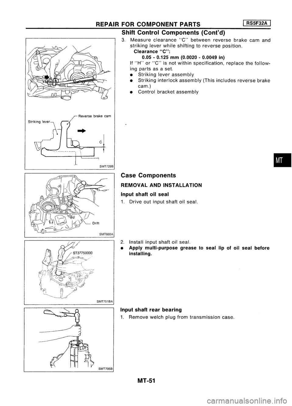
3. Measure clearance "C"between reversebrakecamand
striking leverwhile shifting toreverse position.
Clearance
"C":
0.05 -0.125 mm(0.0020 -0.0049 in)
If "H" or"C" isnot within specification, replacethefollow-
ing parts asaset.
• Striking leverassembly
• Striking interlock assembly (Thisincludes reversebrake
earn.)
• Control bracketassembly
Reverse brakeeam
c SMT729B CaseComponents
REMOVAL ANDINSTALLATION
Input shaftoilseal
1. Drive outinput shaftoilseal.
2. Install inputshaftoilseal.
• Apply multi-purpose greasetoseal lipofoil seal before
installing.
SMT751BA
•
Input shaftrearbearing
1. Remove welchplugfrom transmission case.
SMT705B MT-51
Page 1594 of 1701
ST33290001
REPAIR
FORCOMPONENT PARTS
I
RS5F32A
I
Case Components (Cont'd)
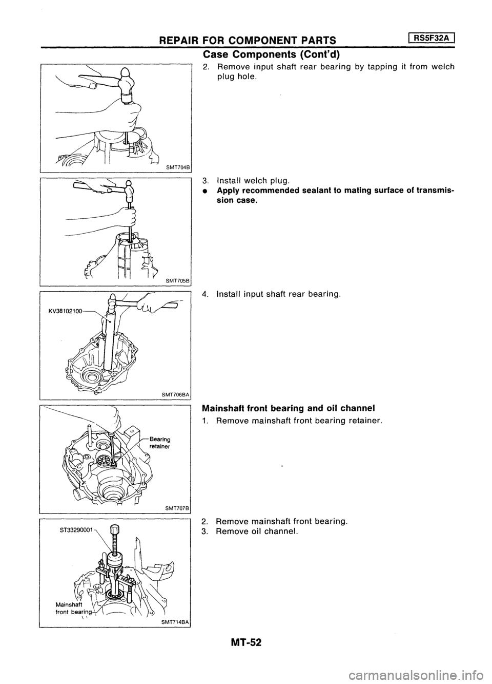
2. Remove inputshaft rearbearing bytapping itfrom welch
plug hole.
SMT704B
3.Install welchplug.
• Apply recommended sealanttomating surface oftransmis-
sion case.
SMT705B
4.Install inputshaft rearbearing.
SMT706BA Mainshaft frontbearing andoilchannel
1. Remove mainshaft frontbearing retainer.
SMT707B
2.Remove mainshaft frontbearing.
3. Remove oilchannel.
SMT714BA MT-52
Page 1595 of 1701
Toward
oil pocket
REPAIR
FORCOMPONENT PARTS
Case Components (Cont'd)
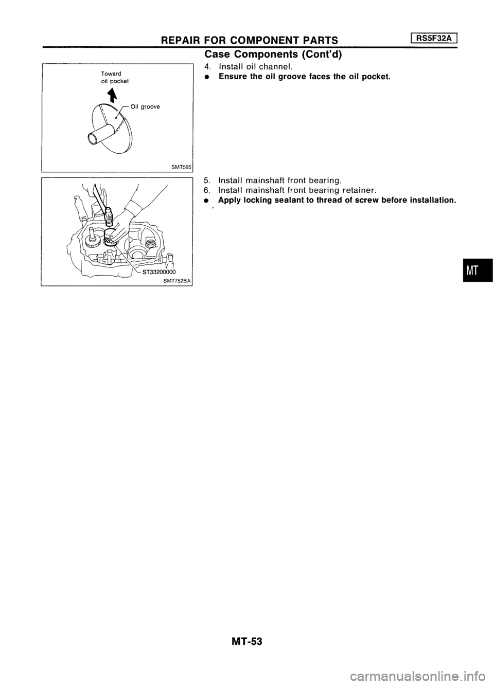
4. Install oilchannel.
• Ensure theoilgroove facestheoilpocket.
SMT595
I
RSSF32A
I
5. Install mainshaft frontbearing.
6. Install mainshaft frontbearing retainer.
• Apply locking sealant tothread ofscrew before installation .
MT-53
•
Page 1596 of 1701
ADJUSTMENT
I
RS5F32A
I
SMT646-A
SMT454-B Differential
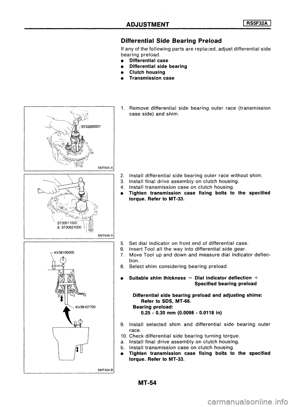
SideBearing Preload
If any ofthe following partsarereplaced, adjustdifferential side
bearing preload.
• Differential case
• Differential sidebearing
• Clutch housing
• Transmission case
1. Remove differential sidebearing outerrace(transmission
case side) andshim.
2. Install differential sidebearing outerracewithout shim.
3. Install finaldrive assembly onclutch housing.
4. Install transmission caseonclutch housing.
• Tighten transmission casefixing boltstothe specified
torque. RefertoMT -33.
5. Set dial indicator onfront endofdifferential case.
6. Insert Toolallthe way intodifferential sidegear.
7. Move Toolupand down andmeasure dialindicator deflec-
tion.
8. Select shimconsidering bearingpreload.
• Suitable shimthickness
=
Dial indicator deflection +
Specified bearingpreload
Differential sidebearing preload andadjusting shims:
Refer toSDS, MT-66.
Bearing preload:
0.25 -0.30 mm(0.0098 -0.0118 in)
9. Install selected shimanddifferential sidebearing outer
race.
10. Check differential sidebearing turningtorque.
a. Install finaldrive assembly onclutch housing.
b. Install transmission caseonclutch housing.
• Tighten transmission casefixing boltstothe specified
torque. RefertoMT-33.
MT-54
Page 1597 of 1701
ADJUSTMENT
I
RS5F32A
I
Differential SideBearing Preload(Cont'd)
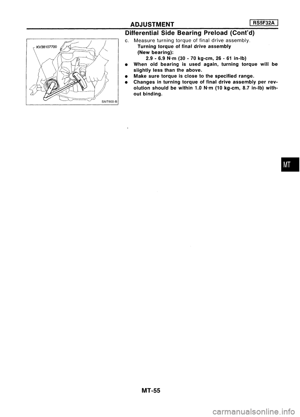
c. Measure turningtorqueoffinal drive assembly.
Turning torqueoffinal drive assembly
(New bearing):
2.9 -6.9 N'm (30-70 kg-em, 26-61 in-Ib)
• When oldbearing isused again, turning torquewillbe
slightly lessthan theabove.
• Make suretorque isclose tothe specified range.
• Changes inturning torqueoffinal drive assembly perrev-
olution shouldbewithin 1.0N'm (10kg-em, 8.7in-Ib) with-
out binding.
MT-55
•
Page 1598 of 1701
ASSEMBLY
I
RS5F32A ,
J
Reverse checkplug
~ Reverse checkspring
V
Check ball(Large)
"-- Check ball(Small)
b~6
,
~
l ~---- -'.
SMT584
SMT688
SMT648AA SMT671B
1.
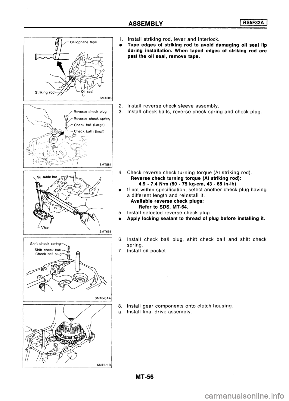
Install striking rod,lever andinterlock.
• Tape edges ofstriking rodtoavoid damaging oilseal lip
during installation. Whentaped edges ofstriking rodare
past theoilseal, remove tape.
2. Install reverse checksleeve assembly.
3. Install check balls,reverse checkspring andcheck plug.
4. Check reverse checkturning torque(Atstriking rod).
Reverse checkturning torque(Atstriking rod):
4.9 -7.4 N'm (50-75 kg-em, 43-65 in-Ib)
• If
not within specification, selectanother checkplughaving
a different lengthandreinstall it.
Available reversecheckplugs:
Refer to
50S,
MT-64.
5. Install selected reversecheckplug.
• Apply locking sealanttothread ofplug before installing it.
6. Install checkballplug, shiftcheck ballandshift check
spring.
7. Install oilpocket.
8. Install gearcomponents ontoclutch housing.
a. Install finaldrive assembly.
MT-56
Page 1599 of 1701
ASSEMBLY
I
RSSF32A
I
SMT666
SMT774B
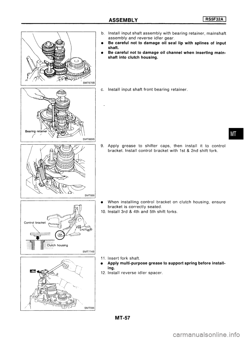
b.
Install inputshaft assembly withbearing retainer, mainshaft
assembly andreverse idlergear.
• Becareful nottodamage oilseal lipwith splines ofinput
shaft.
• Becareful nottodamage oilchannel wheninserting main-
shaft intoclutch housing.
c. Install inputshaftfrontbearing retainer.
9. Apply grease toshifter caps,theninstall itto control
bracket. Installcontrol bracket with1st
&
2nd shift fork.
• When installing controlbracket onclutch housing, ensure
bracket iscorrectly seated.
10. Install 3rd
&
4th and 5thshift forks.
•
SMT596
11.
Insert forkshaft.
• Apply multi-purpose greasetosupport springbefore install-
ing.
12. Install reverse idlerspacer.
MT-57
Page 1600 of 1701
ASSEMBLY
I
RS5F32A
I
SMT666B
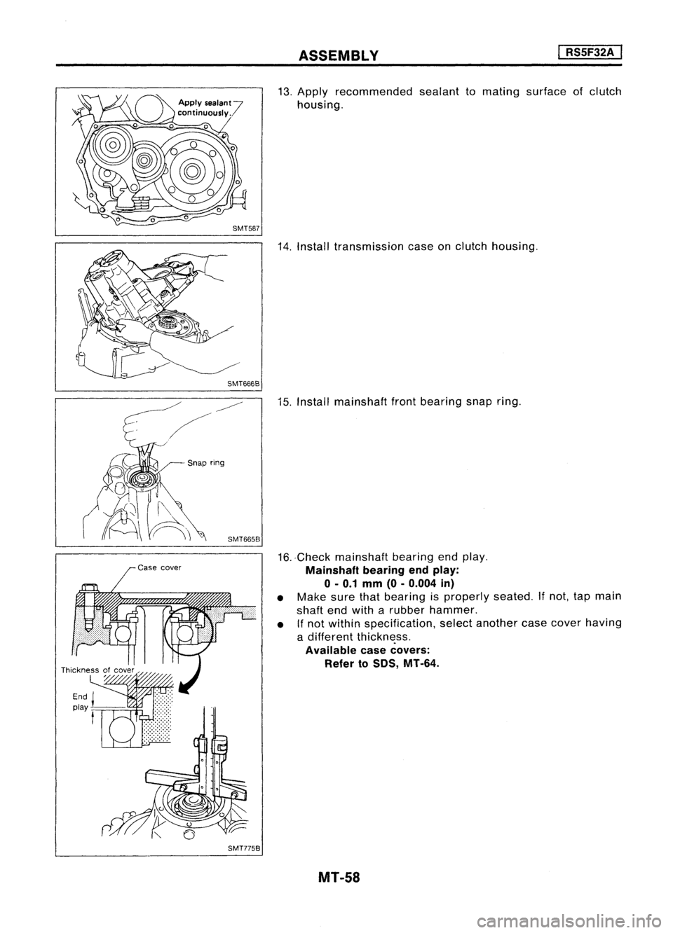
13.
Apply recommended sealanttomating surface ofclutch
housing.
14. Install transmission caseonclutch housing.
Snap ring
SMT665B
SMT775B
15.
Install mainshaft frontbearing snapring.
16. -Check mainshaft bearingendplay.
Mainshaft bearingendplay:
o -
0.1 mm (0-0.004 in)
• Make surethatbearing isproperly seated.
If
not, tapmain
shaft endwith arubber hammer.
• Ifnot within specification, selectanother casecover having
a different thickness.
Available casecovers:
Refer to50S, MT-64.
MT-58
Trending: USB, seats, oil dipstick, tire size, roof rack, Connector B111, instrument cluster
