engine NISSAN ALMERA N15 1995 Service Manual
[x] Cancel search | Manufacturer: NISSAN, Model Year: 1995, Model line: ALMERA N15, Model: NISSAN ALMERA N15 1995Pages: 1701, PDF Size: 82.27 MB
Page 1256 of 1701
![NISSAN ALMERA N15 1995 Service Manual MethodA
Method B 90+5degrees
-0
Engine Paint
mark
front
:0
118
~
(12,87)
Plasticzone
EO
78
0,
(8,58)
~
E
39
z
(4,29)
SEM074DATIMING
CHAIN
[]B]
Installation (Cont'd)
@
Method](/img/5/57349/w960_57349-1255.png "NISSAN ALMERA N15 1995 Service Manual MethodA
Method B 90+5degrees
-0
Engine Paint
mark
front
:0
118
~
(12,87)
Plasticzone
EO
78
0,
(8,58)
~
E
39
z
(4,29)
SEM074DATIMING
CHAIN
[]B]
Installation (Cont'd)
@
Method")
MethodA
Method B 90+5degrees
-0
Engine Paint
mark
front
:0
118
~
(12,87)
Plasticzone
EO
78
0,
(8,58)
~
E
39
z
(4,29)
SEM074DATIMING
CHAIN
[]B]
Installation (Cont'd)
@
Method A:Turn allbolts 90to95 degrees clockwise with
Tool orsuitable anglewrench.
Method B:
If
angle wrench isnot available, dothe follow-
ing. Mark theside ofall bolts withpaint marks
facing thefront ofthe engine. Thenturnthem 90
to 95 degrees clockwise.
CD
Turn allbolts 90to95 degrees clockwise. •
@
Ensure thatpaint mark oneach boltfaces therear ofthe
engine. (Method Bonly)
Do not turn anybolt 180to190 degrees clockwise allatonce.
Tightening torqueN'm(kg-m, ft-Ib)
@
39(4.0, 29)
@
78(8.0, 58)
@
0(0,0)
@
34-44 (3.5 -4.5, 25-33)
@
90-95 degrees (90degree preferred)
CD
90
-95 degrees (90degree preferred)
14. Install cylinder headoutside bolts.
15. Install thefollowing waterhoses.
• Water hoseforcylinder block.
• Water hosesforheater.
16. Install knocksensor harness connector.
EM-77
Page 1257 of 1701
SEM354D
f'J
liquid gasket
Apply
liquidgasket
to the hatched area.
o ~
LHcamshaft endbracket
SEM075DA
RH camShaft./'::~nd bracket
brackey
0
Edb kt
~ "nrace
(1)
~~~;~ ~.o
o.
00'{'
NO.1 to4
0
brackets LHcamshaft
NO.1 to4brackets bracket
SEM098DA TIMING
CHAIN
Installation (Cont'd)
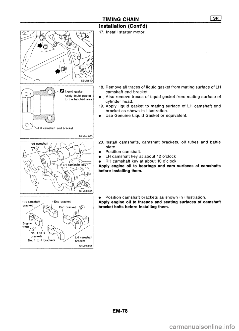
17. Install starter motor.
18. Remove alltraces ofliquid gasket frommating surface ofLH
camshaft endbracket.
•. Also remove tracesofliquid gasket frommating surface of
cylinder head.
19. Apply liquidgasket tomating surface ofLH camshaft end
bracket asshown inillustration.
• Use Genuine LiquidGasket orequivalent.
20. Install camshafts, camshaftbrackets,oiltubes andbaffle
plate.
• Position camshaft.
• LHcamshaft keyatabout 12o'clock
• RHcamshaft keyatabout 10o'clock
Apply engine oiltobearings andcam surfaces ofcamshafts
before installing them.
• Position camshaft bracketsasshown inillustration.
Apply engine oiltothreads andseating surfaces ofcamshaft
bracket boltsbefore installing them.
EM-78
Page 1258 of 1701

• Tightening procedure
STEP 1:
RH camshaft
Tighten bolts
@-
@l
inthat order then
tighten bolts
CD-
@
inthat order.
~: 2N'm (0.2kg-m, 1.4ft-Ib)")
•
TIMING
CHAIN
Installation (Cont'd)
• Tightening procedure
STEP 1:
RH camshaft
Tighten bolts
@-
@l
inthat order then
tighten bolts
CD-
@
inthat order.
~: 2N'm (0.2kg-m, 1.4ft-Ib)
LH camshaft
Tighten bolts
@-
@
inthat order then
tighten bolts
CD-
@l
inthat order.
~: 2N'm (0.2kg-m, 1.4ft-Ib)
STEP 2:
Tighten boltsinthe specified order.
~: 6N'm (0.6kg-m, 4.3ft-Ib)
STEP 3:
Tighten boltsinthe specified order.
Bolt type
@
CID CID ~
(f)
~: 9.8-11.8 N'm
(1.0 -1.2 kg-m, 7.2-8.7 ft-Ib)
Bolt type
@
~: 18-25 N'm
(1.8 -2.6 kg-m, 13-19 ft-Ib)
21. Install camshaft sprockets.
Line upmating marksontiming chainwithmating markson
camshaft sprockets.
SEM987CA
, "--_ ../ / I
SEM696DA
LH
camshaft
Tighten innumerical order.
~ Engine front
•Lock camshafts asshown infigure andtighten tospecified
torque.
~: 137-157 N'm
(14.0 -16.0 kg-m, 101-116 ft-Ib)
Apply engine oiltothreads andseating surfaces ofcamshaft
sprocket boltsbefore installing them.
SEM584D
22.Install timing chainguide.
EM-79
Page 1259 of 1701
![NISSAN ALMERA N15 1995 Service Manual SEM990C
SEM991C TIMING
CHAIN
[]K]
Installation (Cont'd)
23. Install distributor.
• Make surethatposition ofcamshaft isas shown infigure.
• Make surethatNo.1 piston isset at
TOe
andthat di](/img/5/57349/w960_57349-1258.png "NISSAN ALMERA N15 1995 Service Manual SEM990C
SEM991C TIMING
CHAIN
[]K]
Installation (Cont'd)
23. Install distributor.
• Make surethatposition ofcamshaft isas shown infigure.
• Make surethatNo.1 piston isset at
TOe
andthat di")
SEM990C
SEM991C TIMING
CHAIN
[]K]
Installation (Cont'd)
23. Install distributor.
• Make surethatposition ofcamshaft isas shown infigure.
• Make surethatNo.1 piston isset at
TOe
andthat distribu-
tor isset atNo.1 cylinder sparkposition.
24. Install chaintensioner.
Make surethecamshaft sprockets aretightened completely.
Press camstopper downand"press-in" sleeveuntilhook can
be engaged onpin. When tensioner isbolted inposition the
hook willrelease automatically. Makesurearrow "A"points
toward enginefront.
25. Install oilfilter bracket andpower steering oilpump bracket.
EM-80
Page 1260 of 1701

10
(0.39)
n'
Engine front
1+ .,..I
3 (0.12) ~LiqUid
gasket
SEM366D TIMING
CHAIN
Installation (Cont'd)
26. Install intakemanifold supports.
27. Remove allold liquid gasket fr")
Unit:mm(in)
10
(0.39)
n'
Engine front
1+ .,..I
3 (0.12) ~LiqUid
gasket
SEM366D TIMING
CHAIN
Installation (Cont'd)
26. Install intakemanifold supports.
27. Remove allold liquid gasket frommating surfaces ofrocker
cover gasket andcylinder head.
28. Apply acontinuous beadofliquid gasket tomating surfaces
of rocker covergasket andcylinder head.
• Use Genuine LiquidGasket orequivalent.
•
3
1
mm (0.12
In)r~
liquidgasket
tJ$j
SEM367D
@
8l"-L~~[c,.l~
Q
[0 O@O 0
CD
Oil separator
Tighten innumerical order.
SEM585D
29.
Install rocker coverandoilseparator.
(1) Tighten nuts
C!J-
@l -
@ -@ -
cID
inthat order to4N'm
(0.4 kg-m, 35in-Ib).
(2) Tighten nuts
d)
through @innumerical orderto8to 10
N'm (0.8to1.0 kg-m, 69to87 in-Ib).
30. Refit spark plugsandleads.
31. Install vacuum hoses,fuelhoses, wires,harness, connec-
tors andsoon.
32. Install power steering oilpump andalternator.
33. Install waterpumppulley anddrive belts.
34. Refit airduct tointake manifold.
35. Install radiator.
36. Refit hoses andrefill withcoolant. (RefertoMA section.)
37. Install engine sidecover andfront RHwheel.
38. Install engine undercovers.
EM-81
Page 1261 of 1701
.
4. Re")
OILSEAL REPLACEMENT
VALVE OILSEAL
1. Remove accelerator cable.
2. Remove rockercoverandoilseparator.
3. Remove camshafts andsprockets.
Refer to"Removal" in"TIMING CHAIN"(EM-69).
4. Remove sparkplugs.
5. Install airhose adapter intospark plugholeandapply air
pressure tohold valves inplace. Applyapressure of490
kPa (4.9bar, 5kg/cm
2,
71psi).
6. Remove rockerarm,rocker armguide andshim.
Air SEM077D
7.Remove valvespring withTool.
Piston concerned shouldbeset atTOe toprevent valvefrom
falling.
8. Remove valveoilseal.
9. Apply engine oiltonew valve oilseal andinstall itwith Tool.
FRONT OILSEAL
1. Remove thefollowing parts:
• Engine undercover
• Front RHwheel andengine sidecover
• Drive belts
• Crankshaft pulley
2. Remove frontoilseal.
Be careful nottoscratch frontcover.
SEM997C EM-82
Page 1262 of 1701

Engine
/'i
inside
Y
Oil seal lip
Engine
/'i
inside
Y
OIL
SEAL REPLACEMENT
• Install newoilseal inthe direction shown.
~ Engine
Youtside
SEM715A
3.Apply engine oiltonew oilseal andinstall itusing asuit-
able tool.
REAR OILSEAL
1. Remove transaxle. (RefertoMT orAT section.)
2. Remove flywheel ordrive plate.
3. Remove rearoilseal.
Be careful nottoscratch rearoilseal retainer.
SEM999C
•Install newoilseal inthe direction shown.
~ Engine
Youtside
•
4. Apply engine oiltonew oilseal andinstall itusing asuit-
able tool.
SEM001D EM-S3
Page 1264 of 1701
 ~
Refer to\"Installation\" in
\"rIMING CHAIN\".
~stside
~\9
\"'I")
SEC.111.130 CYLINDER
HEAD
~Refer to"Installation" In"riMING CHAIN".
Rocker covergasket ~
20
f) ~
Refer to"Installation" in
"rIMING CHAIN".
~stside
~\9
"'I
Ii ~
~f::l
If;
~ ~
!
l~
\alve oilseal ~
04 ~~
rn, :
Refer to"Installation" in"TIMING CHAIN".
~-J :
N.m (kg-m, ft-Ib)
~ :N.m (kg-m, in-Ib)
~ :Apply liquidgasket.
fJ :
Lubricate withnewengine oil.
SEM722ED
•
G)
Oilfiller cap
@
Camshaft sprocket
@
Rocker cover
@
Camshaft
@ Rocker
armguide
@)
Camshaft
bracket
@ Rocker
arm
@
Oiltube
@)
Shim
@
Water outlet
@
Hydraulic
lashadjuster
@
Cylinder head
(J)
Chain.
tensioner
@
Valve
EM-8S @
Valve spring seat
@
Valve spring
@
Valve spring retainer
@
Valve collet
@
Spark plug
@>
Cylinder headbolt
Page 1265 of 1701

Rocker~armguide-
Rocker arm
Shim
Hydraulic I
o,h .dJ""~
i
!\
'!
OK
~
@
SEM878CA
SEM202D CYLINDER
HEAD
CAUTION:
• Apply newengine oiltothe sliding surfaces wheninstalling
sliding parts.Sliding partsinclude rockerarms,camshafts,
oil seal, etc.
• Apply newengine oiltobolt thread andseat surfaces when
tightening thefollowing: Cylinderheadbolts, camshaft
sprocket boltsandcamshaft bracketbolts.
• Ifa hydraulic lashadjuster iskept onitsside, there isarisk
of air entering it.After removal, alwayssethydraulic lash
adjuster straightup,orkeep itsoaked innew engine oil.
• .Do not disassemble hydrauliclashadjusters.
• Attach tagstolash adjusters soasnot tomix them up.
Removal
• This removal procedure isthe same asfor timing chain.
Refer toEM-69.
Disassembly
1. Remove rockerarms,shims, rockerarmguides andhydrau-
lic lash adjusters fromcylinder head.
CAUTION: Keep partsinorder sothat they canbeinstalled intheir origi-
nal positions duringassembly.
2. Remove crankcase ventilation oilseparator.
3. Remove exhaustmanifold cover.
4. Remove exhaustmanifold.
5. Remove wateroutlet.
EM-86
Page 1267 of 1701

12. Remove valveoilseal with asuitable tool.
Inspection
CYLINDER HEADDISTORTION
. Head surface flatness:
Standard Less than0.03mm(0.0012 in)
Limit
0.1 m")
SEM925CCYLINDER
HEAD
Disassembly (Cont'd)
12. Remove valveoilseal with asuitable tool.
Inspection
CYLINDER HEADDISTORTION
. Head surface flatness:
Standard Less than0.03mm(0.0012 in)
Limit
0.1 mm (0.004 in)
If beyond thespecified limit,replace orresurface.
Resurfacing limit:
The resurfacing limitofcylinder headisdetermined bythe cyl-
inder block resurfacing inan engine.
Amount ofcylinder headresurfacing is
"A".
Amount ofcylinder blockresurfacing is
"B".
The maximum limitisas follows:
A
+
B
=
0.2 mm (0.008 in)
After resurfacing cylinderhead,check thatcamshaft rotates
freely byhand. Ifresistance isfelt, cylinder headmustbe
replaced.
Nominal cylinderheadheight:
136.9 -137.1 mm(5.390 -5.398 in)
CAMSHAFT VISUALCHECK
Check camshaft forscratches, seizureandwear.
CAMSHAFT RUNOUT
1. Measure camshaft runoutatthe center journal.
Runout (Totalindicator reading):
Standard Less than0.02mm(0.0008 in)
Limit
0.1 mm (0.004 in)
2. Ifitexceeds thelimit, replace camshaft.
EM-88