NISSAN ALMERA N15 1995 Manual PDF
ALMERA N15 1995
NISSAN
NISSAN
https://www.carmanualsonline.info/img/5/57349/w960_57349-0.png
NISSAN ALMERA N15 1995 Manual PDF
Trending: Tachome, technical specifications, gas type, coolant level, key battery, airbag, transmission
Page 71 of 1701
REPAIRFORCOMPONENT PARTS
Oil Pump (Cont'd)
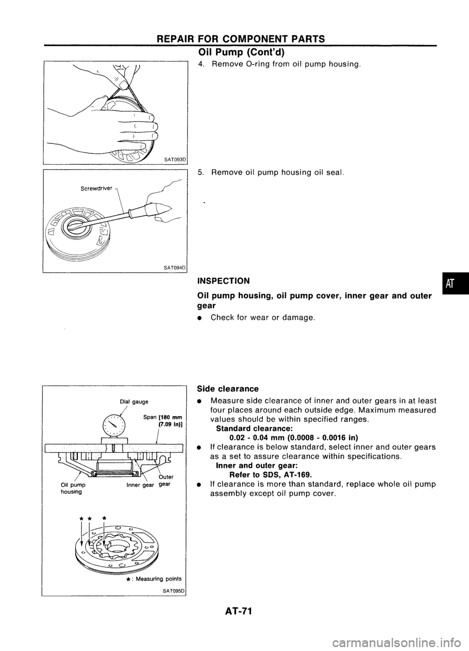
4. Remove O-ringfromoilpump housing.
(
(
~) SAT093D
5.Remove oilpump housing oilseal.
SAT094D INSPECTION
Oil pump housing, oilpump cover, innergearandouter
gear
• Check forwear ordamage.
•
Oil pump
housing Dial
gauge
/
Span(180
mm
(7.09
In)]
Inner gear Side
clearance
• Measure sideclearance ofinner andouter gears inat least
four places around eachoutside edge.Maximum measured
values should bewithin specified ranges.
Standard clearance:
0.02 -0.04
mm
(0.0008 -0.0016
in)
• Ifclearance isbelow standard, selectinnerandouter gears
as aset toassure clearance withinspecifications.
Inner andouter gear:
Refer toSOS, AT-169.
• Ifclearance ismore thanstandard, replacewholeoilpump
assembly exceptoilpump cover.
*:
Measuring points
SAT095D
AT-71
Page 72 of 1701
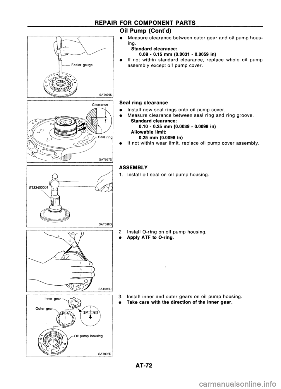
SAT0960Sealringclearance
• Install newseal rings ontooilpump cover.
• Measure clearance betweensealringandring groove.
Standard clearance:
0.10 -0.25 mm(0.0039 -0.0098 in)
Allowable limit:
0.25 mm(0.0098 in)
• Ifnot within wearlimit,replace oilpump coverassembly.
ASSEMBLY
1. Install oilseal onoil pump housing.
2. Install O-ring onoil pump housing.
• Apply ATFtoO-ring.
3. Install innerandouter gears onoil pump housing.
• Take carewiththedirection ofthe inner gear.
REPAIR
FORCOMPONENT PARTS
Oil Pump (Cont'd)
• Measure clearance betweenoutergearandoilpump hous-
ing.
Standard clearance:
0.08 -0.15 mm(0.0031 -0.0059 in)
• Ifnot within standard clearance, replacewholeoilpump
assembly exceptoilpump cover.
AT-72
Page 73 of 1701
REPAIRFORCOMPONENT PARTS
Oil Pump (Conl'd)
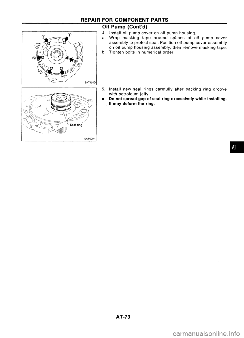
4. Install oilpump cover onoil pump housing.
a. Wrap masking tapearound splines ofoil pump cover
assembly toprotect seal.Position oilpump cover assembly
on oil pump housing assembly, thenremove masking tape.
b. Tighten boltsinnumerical order.
SAT101D
5.Install newseal rings carefully afterpacking ringgroove
with petroleum jelly.
• Donot spread gapofseal ringexcessively whileinstalling .
. It may deform thering.
SAT699H
AT-73
•
Page 74 of 1701
SEC.317
~ :N.m (kg-m, in-Ib)
'I :Model 34X68
'2 :Model 34X69, 34X70.
34X80, 34X81
Model
34X68
Model
34X69,
34X70.
34X80,
34X81 REPAIR
FORCOMPONENT PARTS
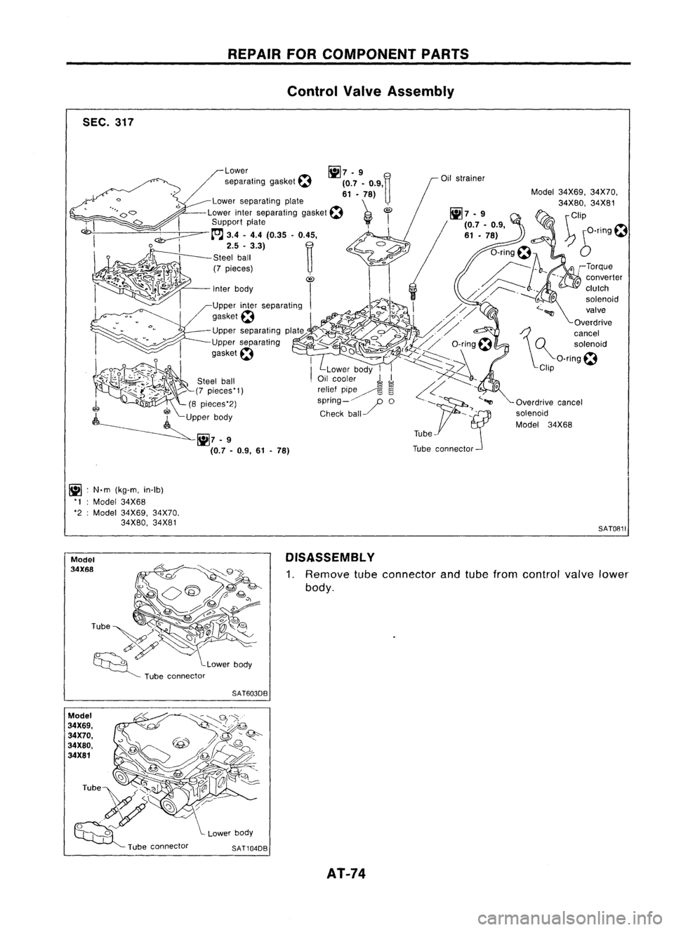
Control ValveAssembly
Model34X69, 34X70,
34X80, 34X81
\ Clip
~ 6-T1ng~
SATOB11
DISASSEMBL Y
1. Remove
tubeconnector andtube from control
valve
lower
body.
SAT603DB
SAT104DB AT-74
Page 75 of 1701
SAT245EB
Nut
Section Z- Z
Reamer bolt
•
Bolt
symbol
@
@ @@
CID
cD
Bolt length 'T'
13.558.0 40.0 66.033.078.0
~Qmm(in)
(0.531)
(2.283)(1.575)(2.598) (1.299)
(3.071)
Number ofbolts
4
3 611
22
Bolt symbol
@
@ @@
CID
CD
Bolt length" ("
13.558.0 40.0
66.0 33.078.0
~ (0.531)(2.283)
(1.575)(2.598) (1.299)(3.071)
>-,-1
Qmm (in)
Number ofbolts
53 611
22
With
torque converter clutchsolenoid valve
@
@
REPAIR
FORCOMPONENT PARTS
Control ValveAssembly (Cont'd)
2. Disassemble upper,interandlower bodies usingthefollow-
ing procedures.
Bolt length, number andlocation:
Without torqueconverter clutchsolenoid valve
CD
Plain
washer
Section
y- y
Model
34X68
Section Y- Y
@Bolt~
Support plate
f
(E)BOIt~
Support plate~
(f)
Plain
washer
Nut SAT515HB
Model 34X68
a.
Remove bolts@,@and
CB
shown inthe illustration.
b. Remove oilstrainer fromcontrol valveassembly.
AT-75
Page 76 of 1701
Model34X69. 34X70.34X80,34X81 REPAIR
FORCOMPONENT PARTS
Control ValveAssembly (Cont'd)
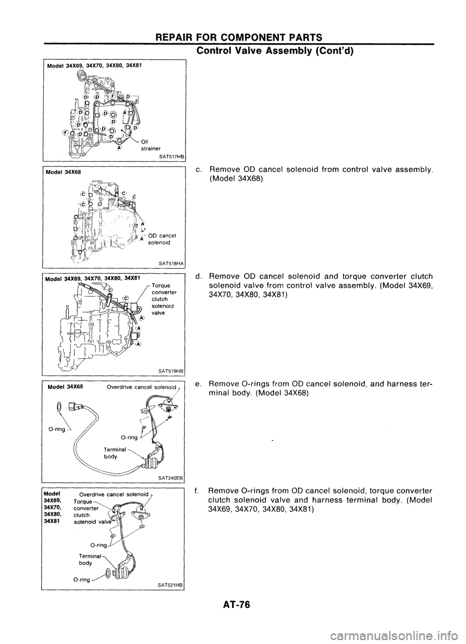
Model 34X68
c.
Remove aDcancel solenoid fromcontrol valveassembly.
(Model 34X68)
Model 34X69. 34X70,34X80.34X81
~)
Model 34X68
Ori~
Torque
converter
clutch
solenoid
valve
SAT519HB
SAT240EB
d.
Remove aDcancel solenoid andtorque converter clutch
solenoid valvefromcontrol valveassembly. (Model34X69,
34X70, 34X80, 34X81)
e. Remove a-ringsfromaDcancel solenoid, andharness ter-
minal body. (Model 34X68)
ModeJ
34X69.
34X70.
34X80.
34X81
Overdrive
cancelsolenoid
Torque
converter
clutch
'0
solenoid valv~
"
o_rin~
Terminal
0
body
O-ring~
l\
SAT521HB
f.
Remove a-ringsfromaDcancel solenoid, torqueconverter
clutch solenoid valveandharness terminal body.(Model
34X69, 34X70, 34X80,34X81)
AT-76
Page 77 of 1701
SAT107DATurnoverlower body,andremove accumulator support•
plate.
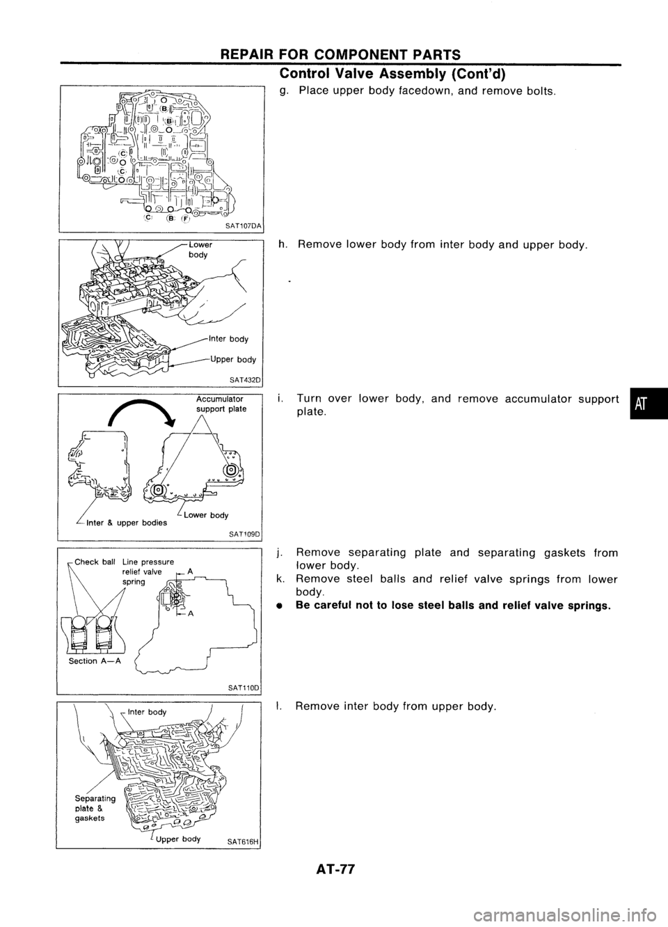
h.
Remove lowerbodyfrom interbody andupper body.
i.
REPAIR
FORCOMPONENT PARTS
Control ValveAssembly (Cont'd)
g. Place upper bodyfacedown, andremove bolts.
Accumulator
support plate
SAT109D
Section A-ALine
pressure
relief valve
spring
j.
Remove separating plateandseparating gasketsfrom
lower body.
k. Remove steelballsandrelief valve springs fromlower
body.
• Becareful nottolose steel ballsandrelief valve springs.
SAT110D I.Remove interbody fromupper body.
AT-77
Page 78 of 1701
REPAIRFORCOMPONEN
Control Val TPARTS
ve Asse b
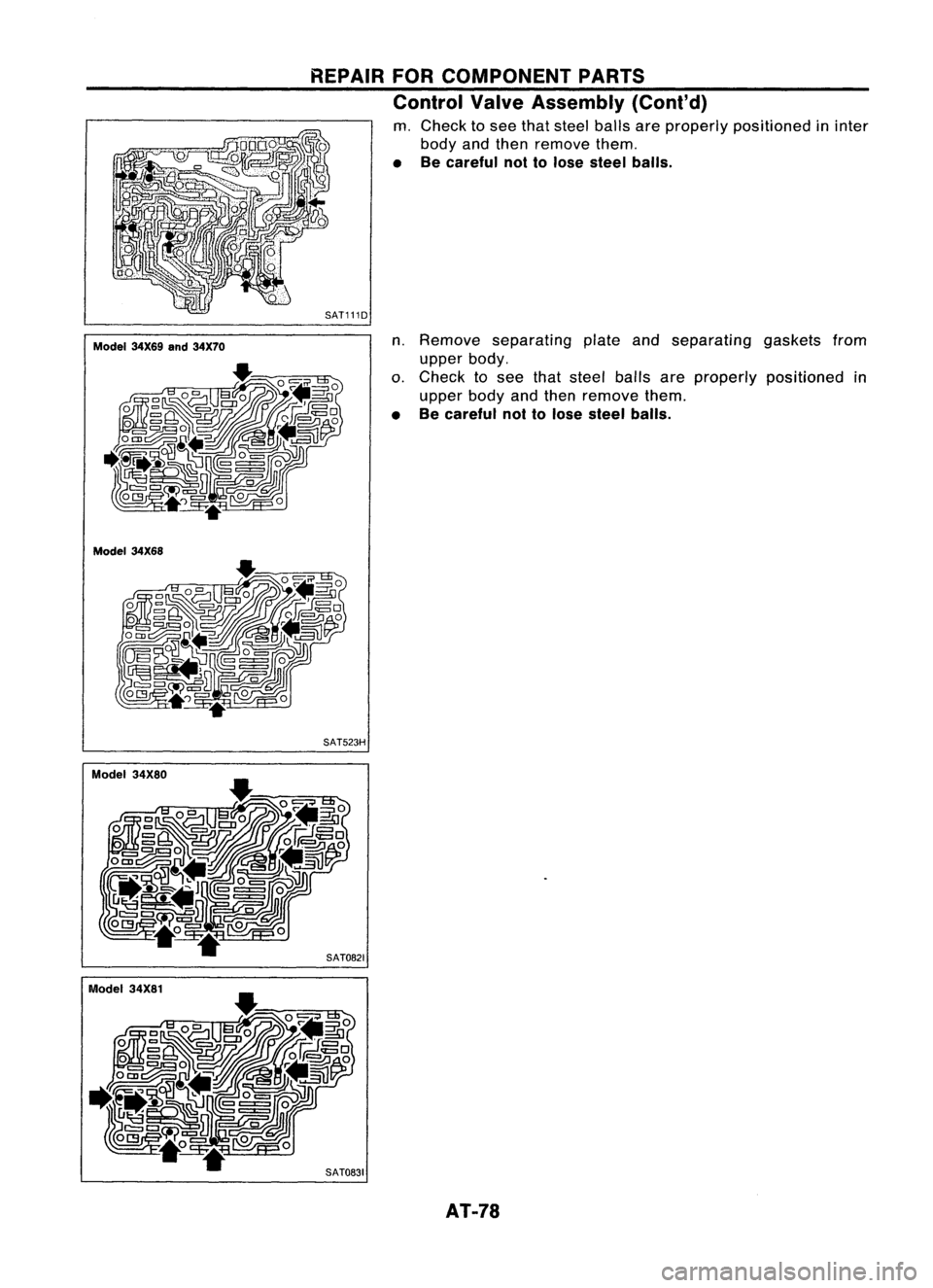
m. Check tosee that
mIy(Cont'd)
body andth steelballsar
• Becareful n~~;:ml ove them. eproperly positioned in.
ose steel b Inter
ails.
SAT111D
Model 34X69
and34X70
Model 34X68
n.
Remo
veseparatin
upper body 9plate and
o. Check tos. separatinggask
upper bodye:n~ht steelballsare elsfrom
• Becareful nollo
~en
remove themproperly positioned.
ose steel balls. .
In
Model 34X80
Model 34X81 SAT523H
SAT0831 AT-78
Page 79 of 1701
REPAIRFORCOMPONENT PARTS
Control ValveAssembly (Cont'd)
INSPECTION
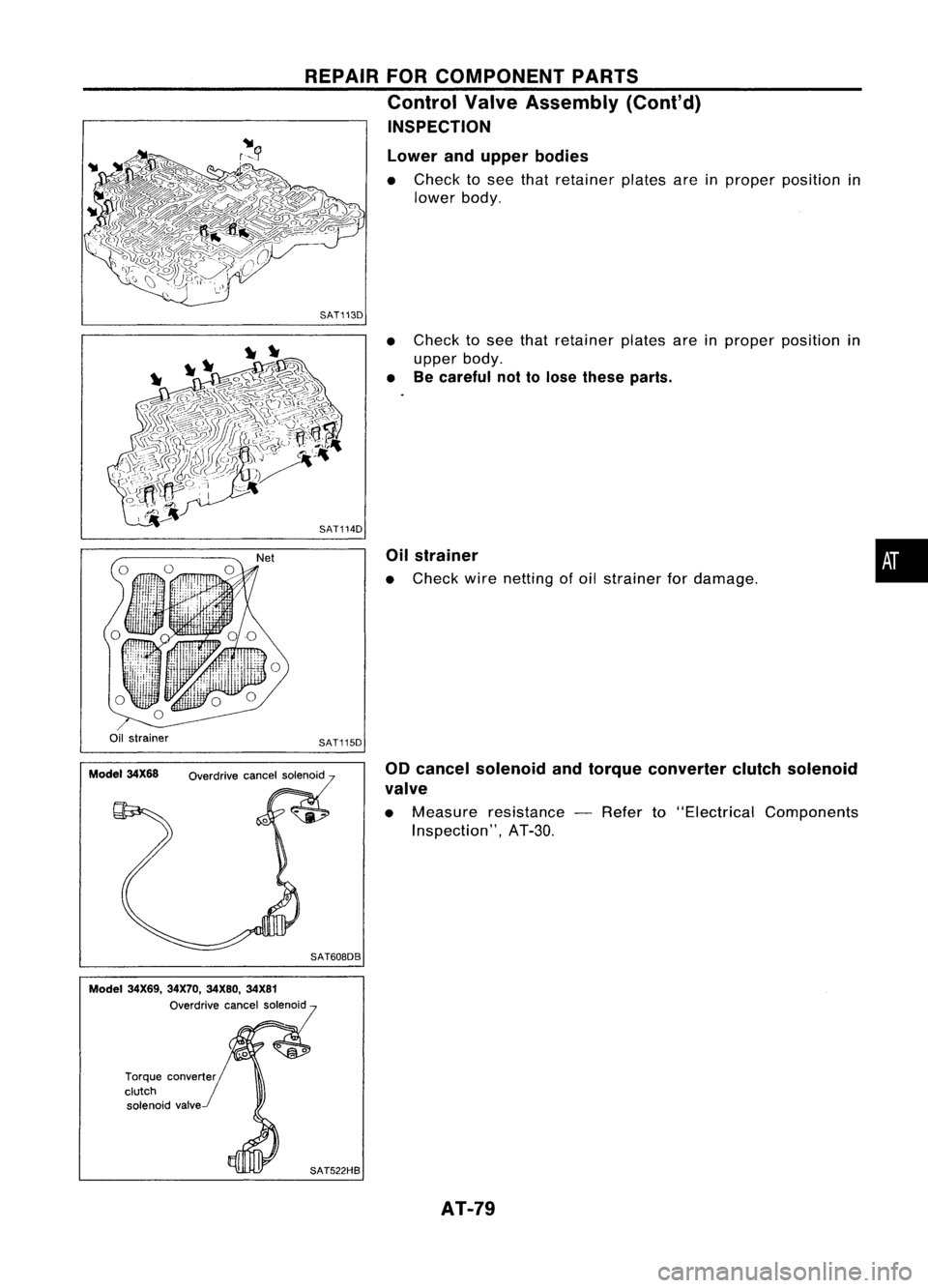
Lower andupper bodies
• Check tosee that retainer platesareinproper position in
lower body.
SAT113D
•Check tosee that retainer platesareinproper position in
upper body.
• Becareful nottolose these parts.
Oil strainer
• Check wirenetting ofoil strainer fordamage.
•
Oil strainer
Model 34X68 SAT115D
Overdrive cancelsolenoid
SAT608DB 00
cancel solenoid andtorque converter clutchsolenoid
valve
• Measure resistance -Refer to"Electrical Components
Inspection", AT-3D.
Model 34X69, 34X70,34X80, 34X81
Overdrive cancelsolenoid
Torque converter
clutch solenoid valve
SAT522HBAT-79
Page 80 of 1701
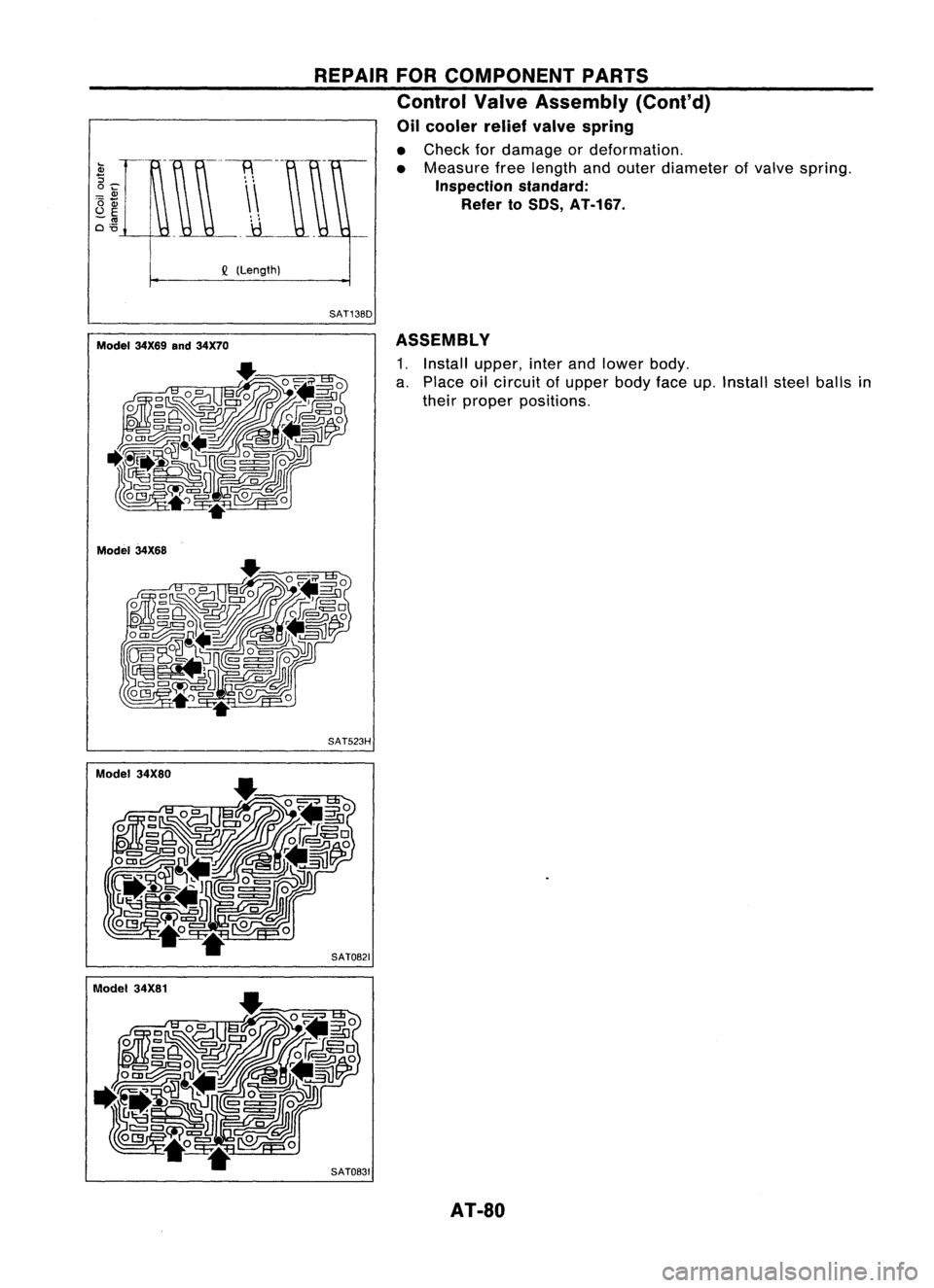
ASSEMBLY
1. Install
a PI upper, inter
. tha~e oilcircuit ofuand lower body
elr pro pperbd .
per posT
0
Yface
I
Ions. up.Install stelb'
e
ails
In
SATOB21
SATOB31
REPAIR
FOR
COMPONE
Control ValNTPARTS
0"1
veAsse b
I
cooler reli
f
mIy(Cont'd)
• Check f
evalve spring
• M ordamag
easure freeIeeor deformation
Inspection
ngthandouter d'.
R
f
standard"
Iameter
of
e er to50S AT.
valvespring
, -167. .
Q
(Length)
Model 34X69and34X70
Model 34X68
Model 34X80
AT-SO
Trending: steering wheel, auxiliary battery, Aiming, AUX, interior spot, clock, low beam
