NISSAN ALMERA N15 1995 Owners Manual
Manufacturer: NISSAN, Model Year: 1995, Model line: ALMERA N15, Model: NISSAN ALMERA N15 1995Pages: 1701, PDF Size: 82.27 MB
Page 91 of 1701
REPAIRFORCOMPONENT PARTS
Control ValveLower Body(Cont'd)
DISASSEMBL Y
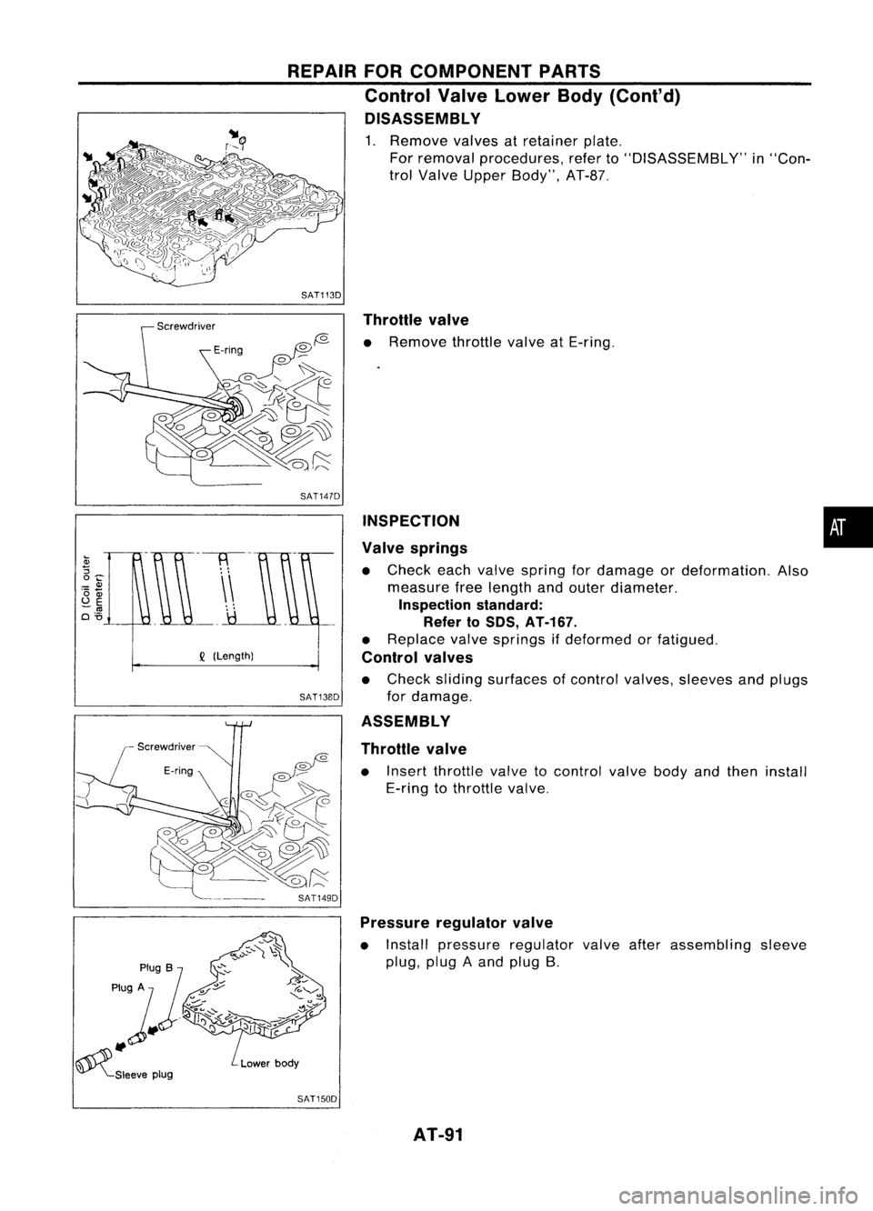
1. Remove valvesatretainer plate.
For removal procedures, referto"DISASSEMBLY" in"Con-
trol Valve Upper Body", AT-B?
SAT1130 Throttle valve
o
f2- •
Remove throttlevalveatE-ring.
•
INSPECTION
Valve springs
• Check eachvalve spring fordamage ordeformation. Also
measure freelength andouter diameter.
Inspection standard:
Refer to50S, AT-167.
• Replace valvesprings ifdeformed orfatigued.
Control valves
• Check sliding surfaces ofcontrol valves, sleeves andplugs
for damage.
ASSEMBLY
Throttle valve
• Insert throttle valvetocontrol valvebodyandthen install
E-ring tothrottle valve.
SAT147D
SAT13BO
Q
(Length)
SAT1490Pressure regulator valve
• Install pressure regulator valveafterassembling sleeve
plug, plugAand plug B.
SAT1500 AT-91
Page 92 of 1701
REPAIRFORCOMPONENT PARTS
Control ValveLower Body(Cont'd)
3-4 shift valve and2-3shift valve
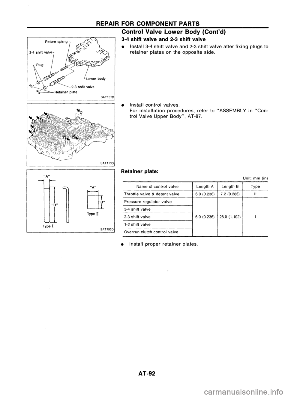
• Install 3-4shift valve and2-3shift valve afterfixing plugsto
retainer platesonthe opposite side.
SAT151D
•Install control valves.
For installation procedures, referto"ASSEMBLY in"Con-
trol Valve Upper Body", AT-8?
SAT113D
"A"
"B"
U
Type I
"A"
Eli
Type II
SAT153D Retainer
plate:
Unit:mm(in)
Name ofcontrol
valve
Length
ALength 8 Type
Throttle
valve
&
detent
valve 6.0(0.236) 7.2(0.283)
1/
Pressure regulator
valve
3-4
shift
valve
2-3
shift valve
6.0(0.236) 28.0(1.102)
I
1-2
shift valve
Overrun
clutchcontrol
valve
• Install proper retainer plates.
AT-92
Page 93 of 1701
REPAIRFORCOMPONENT PARTS
Reverse Clutch
Piston
* :
Select proper thickness.
~. ApplyATF.
Oil
seal~@D
D-ring~
@:>
Snap ring~
Dish
plate
Drive plate
SEC.
315
Retaining plate
*
Snap ring
I
Driven plate
Snap ring~
SAT940HA
DISASSEMBLY •
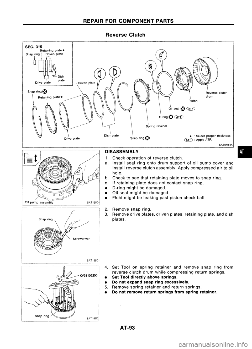
1. Check operation ofreverse clutch.
a. Install sealringonto drum support ofoil pump cover and
install reverse clutchassembly. Applycompressed airtooil
hole.
b. Check tosee that retaining platemoves tosnap ring.
c. Ifretaining platedoesnotcontact snapring,
• D-ring mightbedamaged.
• Oilseal might bedamaged.
• Fluid might beleaking pastpiston checkball.
2. Remove snapring.
3. Remove driveplates, drivenplates, retaining plate,anddish
plates.
SAT156D
KV31103200
SAT157D
4.
Set Tool onspring retainer andremove snapringfrom
reverse clutchdrumwhilecompressing returnsprings.
• Set Tool directly abovesprings.
• Donot expand snapringexcessively.
5. Remove springretainer andreturn springs.
• Donot remove returnsprings fromspring retainer.
AT-93
Page 94 of 1701
REPAIRFORCOMPONENT PARTS
Reverse Clutch(Cont'd)
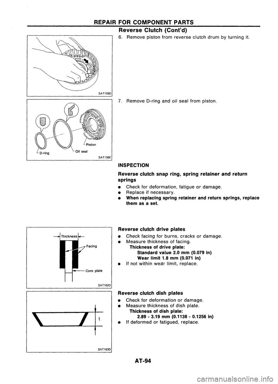
6. Remove pistonfromreverse clutchdrumbyturning
it.
SAT159D
7.Remove O-ringandoilseal from piston.
SAT13BE INSPECTION
Reverse clutchsnapring,spring retainer andreturn
springs
• Check fordeformation, fatigueordamage.
• Replace ifnecessary.
• When replacing springretainer andreturn springs, replace
them asaset.
Reverse clutchdriveplates
• Check facingforburns, cracks ordamage.
• Measure thickness offacing.
Facing Thicknessofdrive plate:
Standard value2.0mm (0.079 in)
Wear limit1.8mm (0.071 in)
• Ifnot within weC1rlimit,replace.
SAT162D Reverse clutchdishplates
• Check fordeformation ordamage.
• Measure thickness ofdish plate.
Thickness ofdish plate:
2.89 -3.19 mm(0.1138 -0.1256 in)
• Ifdeformed orfatigued, replace.
SAT163D AT-94
Page 95 of 1701
Checkairdoes notflow
through ballhole.
REPAIR
FORCOMPONENT PARTS
Reverse Clutch(Cont'd)
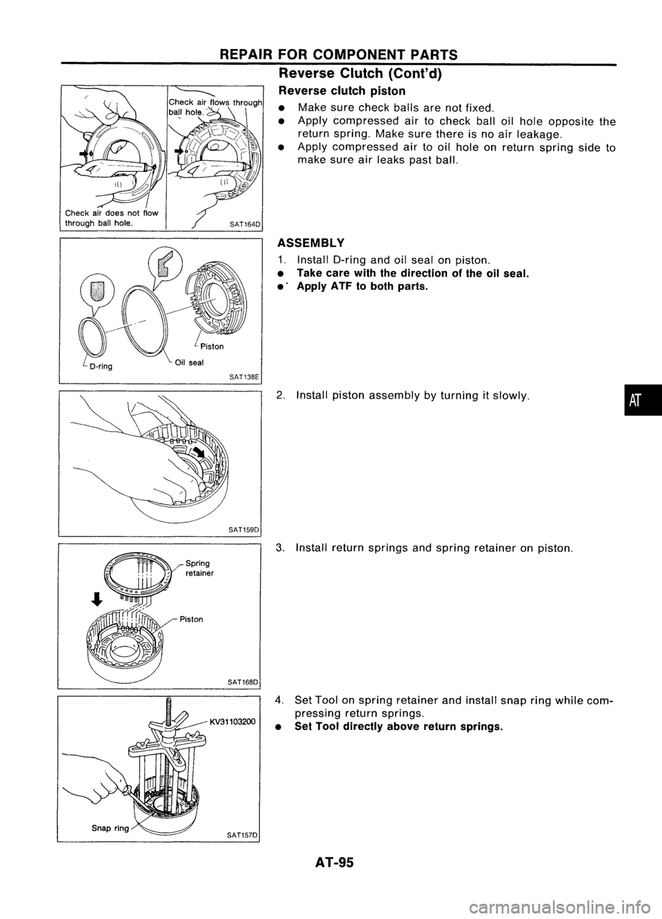
Reverse clutchpiston
• Make surecheck ballsarenotfixed.
• Apply compressed airtocheck balloilhole opposite the
return spring. Makesurethere isno air leakage.
• Apply compressed airtooil hole onreturn spring sideto
make sureairleaks pastball.
SAT164D ASSEMBLY
1. Install O-ring andoilseal onpiston.
• Take carewiththedirection ofthe oilseal.
• Apply ATFtoboth parts.
Oil seal
SAT138E
2.Install piston assembly byturning itslowly.
SAT159D
•
Piston Spring
retainer
SAT168D
KV31103200
SAT157D
3.
Install return springs andspring retainer onpiston.
4. SetTool onspring retainer andinstall snapringwhile com-
pressing returnsprings.
• Set Tool directly abovereturnsprings.
AT-95
Page 96 of 1701
REPAIRFORCOMPONENT PARTS
Reverse Clutch(Cont'd)
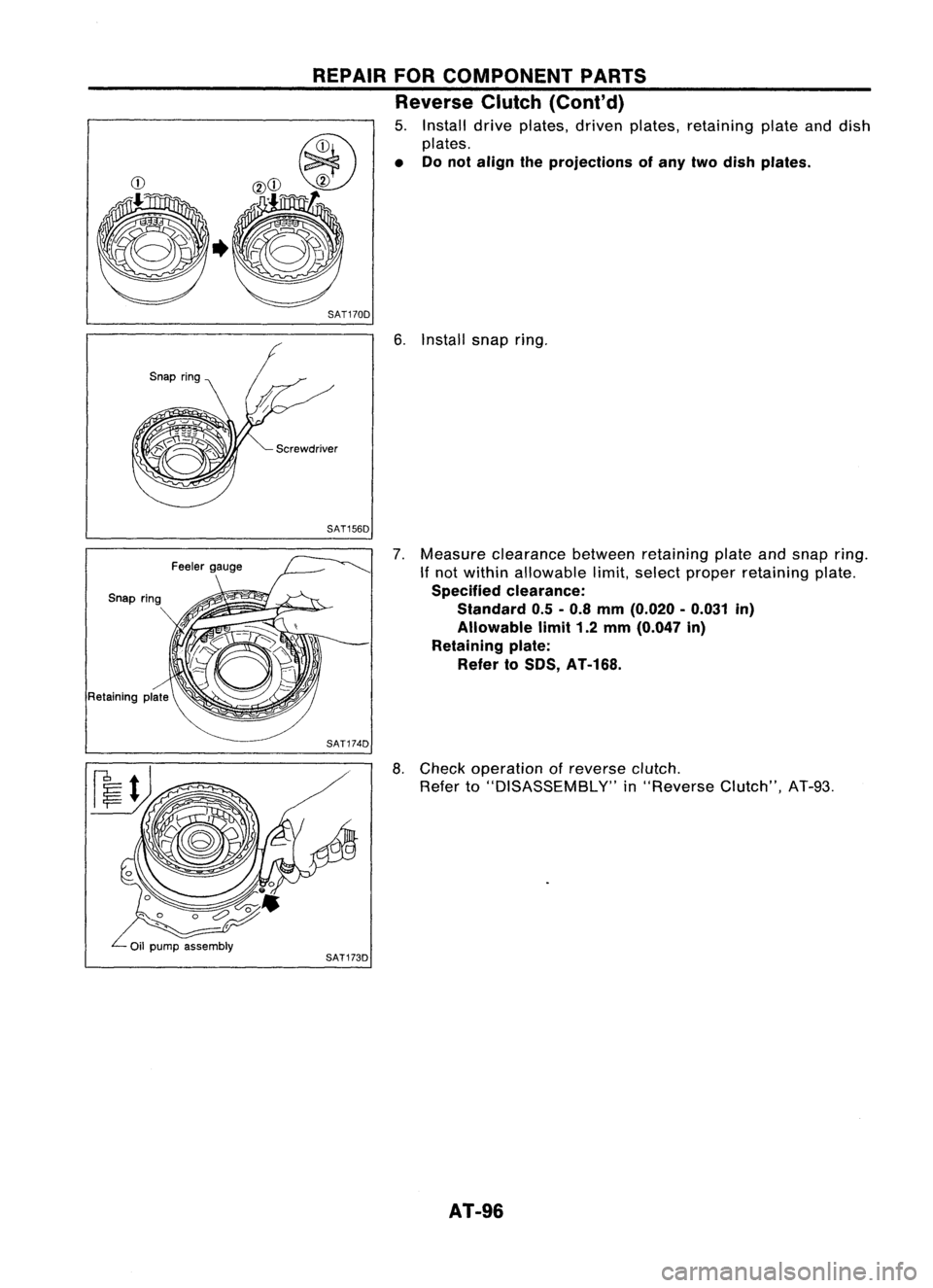
5. Install driveplates, drivenplates, retaining plateanddish
plates.
• Donot align theprojections ofany twodish plates.
~CD
evCD
?
.~
jjfu
SAT170D
6.Install snapring.
SAT156D
Retaining plate
7.
Measure clearance betweenretaining plateandsnap ring.
If
not within allowable limit,select proper retaining plate.
Specified clearance:
Standard 0.5-0.8 mm (0.020 -0.031 in)
Allowable limit1.2mm (0.047 in)
Retaining plate:
Refer toSOS, AT-168.
SAT174D
8.Check operation ofreverse clutch.
Refer to"DISASSEMBLY" in"Reverse Clutch",AT-93.
AT-96
Page 97 of 1701
REPAIRFORCOMPONENT PARTS
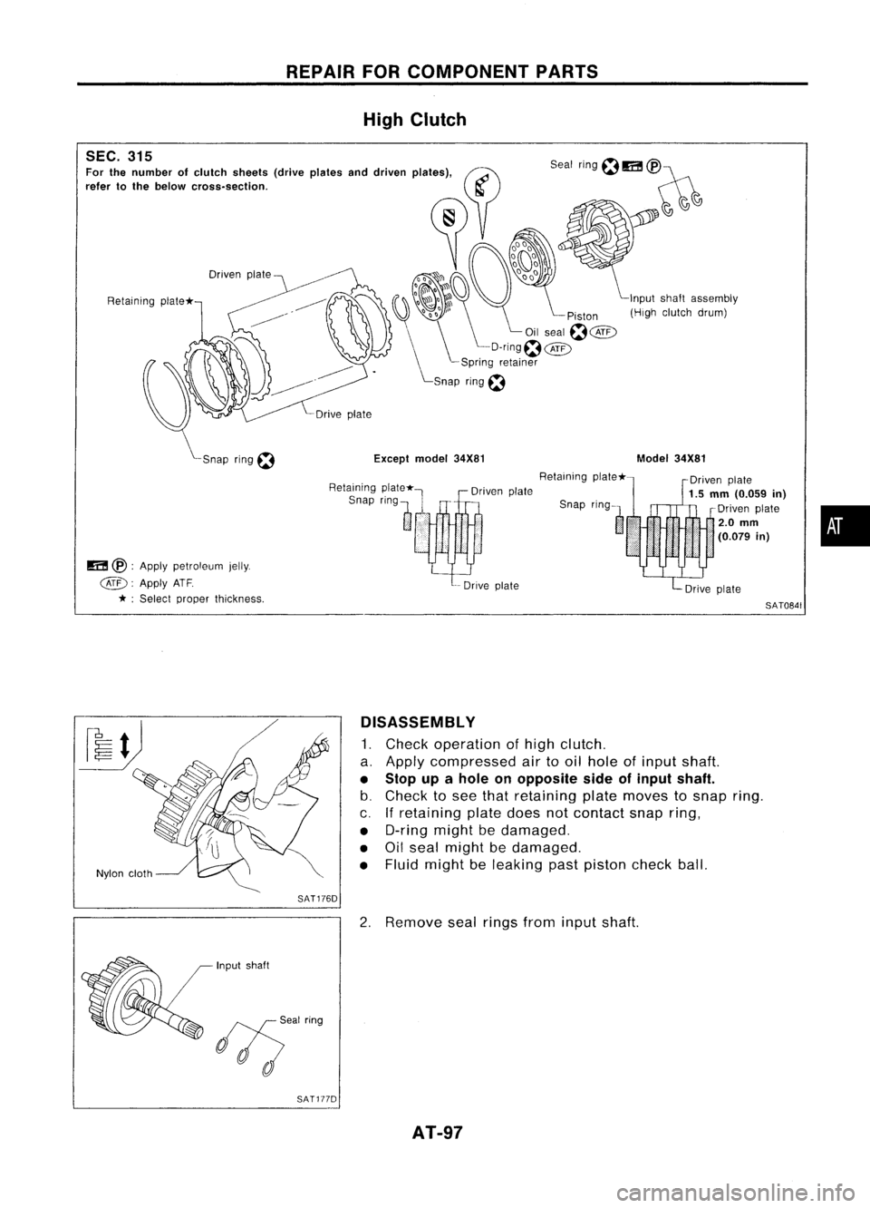
High Clutch
SEC. 315
Fa< th.oumh" of,Iuloh ,h.of. (d".,pI".... dd,I ...
PI'@(if)
,,',' to
fh'
"'ow
010.... ""00. ~)~
Driven
plate
Retaining plate* Input
shaft assembly
(High clutch drum)
Except model34X81
Snap ring
f:1
m
@•
Apply petroleum jelly.
@.
ApplyATF
* ;Select proper thickness. Retaining
Snap ring
l
Driven
plate
-- Drive plate Retaining
plate*-
Model
34X81
Driven
plate
1.5
mm
(0.059
in)
Driven plate
i
2.0
mm
•.•. (0.079
in)
SAT0841
•
Nylon cloth
SAT176D
Input shaft
1/5'"
hog
SAT177D DISASSEMBLY
1. Check operation ofhigh clutch.
a. Apply compressed airtooil hole ofinput shaft.
• Stop upahole onopposite sideofinput shaft.
b. Check tosee that retaining platemoves tosnap ring.
c. Ifretaining platedoesnotcontact snapring,
• O-ring mightbedamaged.
• Oilseal might bedamaged.
• Fluid might beleaking pastpiston checkball.
2. Remove sealrings frominput shaft.
AT-97
Page 98 of 1701
Snapring,
REPAIR
FORCOMPONENT PARTS
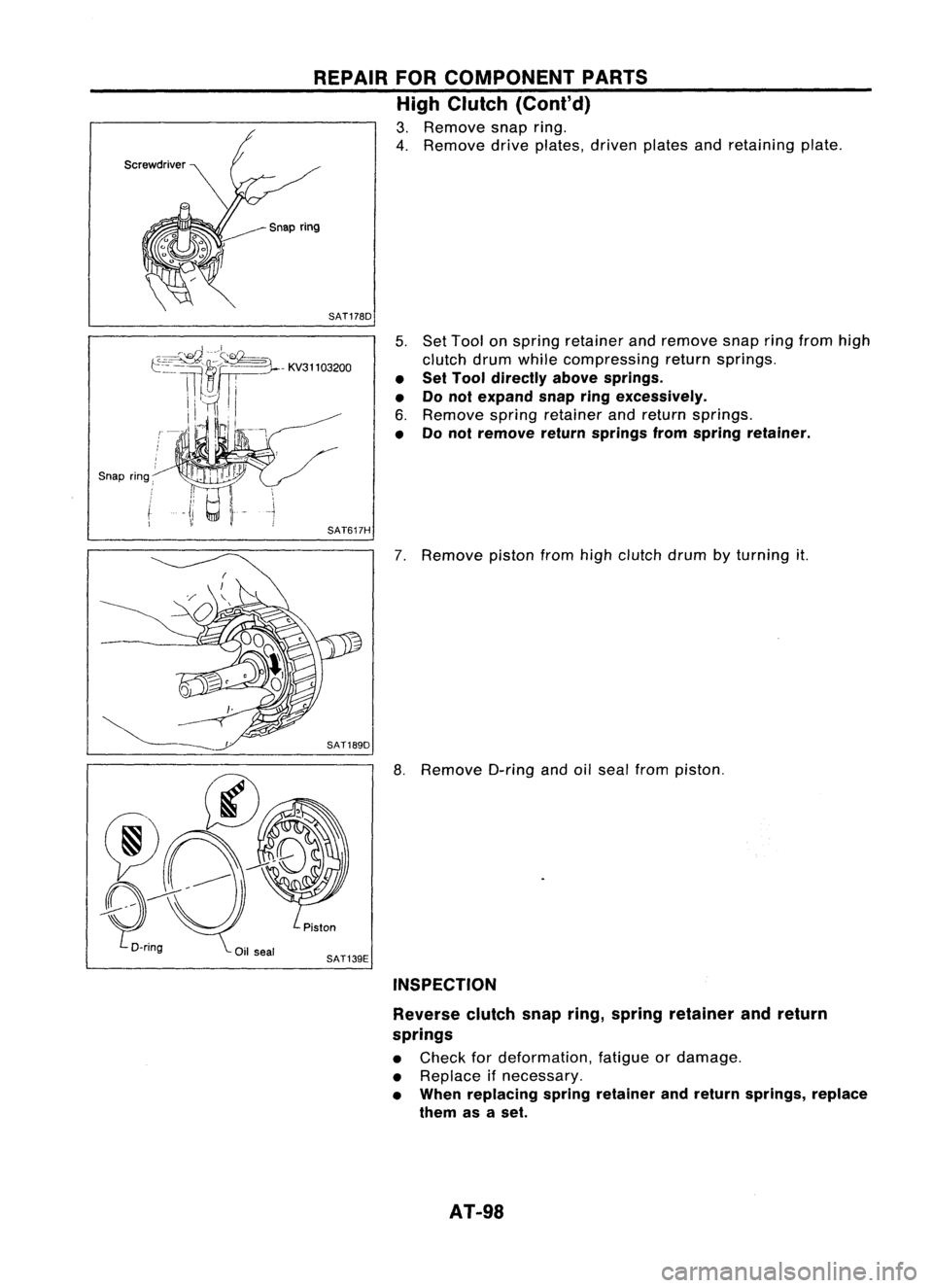
High Clutch (Cont'd)
3. Remove snapring.
4. Remove driveplates, drivenplatesandretaining plate.
SAT178D
5.Set Tool onspring retainer andremove snapringfrom high
clutch drumwhile compressing returnsprings.
• Set Tool directly abovesprings.
• Donot expand snap
ring
excessively.
6. Remove springretainer andreturn springs.
• Donot remove returnsprings fromspring retainer.
SAT617H
7.Remove pistonfromhighclutch drumbyturning it.
8. Remove O-ringandoilseal from piston.
SAT139E INSPECTION
Reverse clutchsnapring,spring retainer andreturn
springs
• Check fordeformation, fatigueordamage.
• Replace ifnecessary.
• When replacing springretainer andreturn springs, replace
them asaset.
AT-98
Page 99 of 1701
•
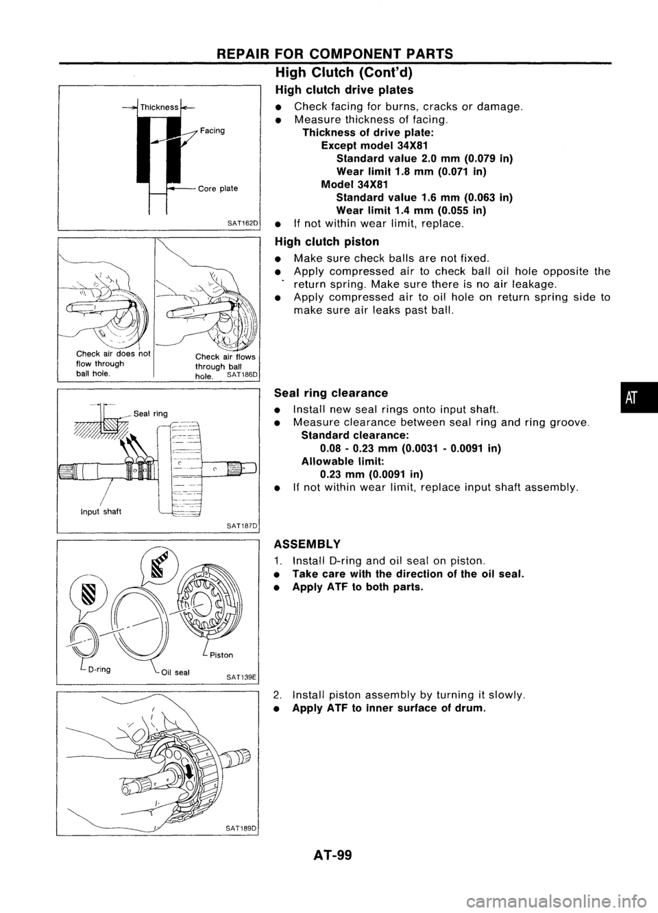
Seal
ringclearance
• Install newseal rings ontoinput shaft.
• Measure clearance betweensealringandring groove.
Standard clearance:
0.08 -0.23 mm(0.0031 -0.0091 in)
Allowable limit:
0.23 mm(0.0091 in)
• If
not within wearlimit,replace inputshaftassembly.
REPAIR
FORCOMPONENT PARTS
High Clutch (Cont'd)
High clutch driveplates
• Check facingforburns, cracks ordamage.
• Measure thickness offacing.
Thickness ofdrive plate:
Except model34X81
Standard value2.0mm (0.079 in)
Wear limit1.8mm (0.071 in)
Model 34X81
Standard value1.6mm (0.063 in)
Wear limit1.4mm (0.055 in)
SAT162D •
Ifnot within wearlimit,replace.
High clutch piston
• Make surecheck ballsarenotfixed.
• Apply compressed airtocheck balloilhole opposite the
return spring. Makesurethere isno air leakage.
• Apply compressed airtooil hole onreturn spring sideto
make sureairleaks pastball.
Facing
Core plate
Check airflows
through ball
hole. SAT186D
Input shaft
I
I
Check airdoes not
flow through
ball hole.
SAT187D
ASSEMBLY
1. Install O-ringandoilseal onpiston.
• Take carewiththedirection ofthe oilseal.
• Apply ATFtoboth parts.
2. Install pistonassembly byturning itslowly.
• Apply ATFtoinner surface ofdrum.
AT-99
Page 100 of 1701
REPAIRFORCOMPONENT PARTS
High Clutch (Cont'd)
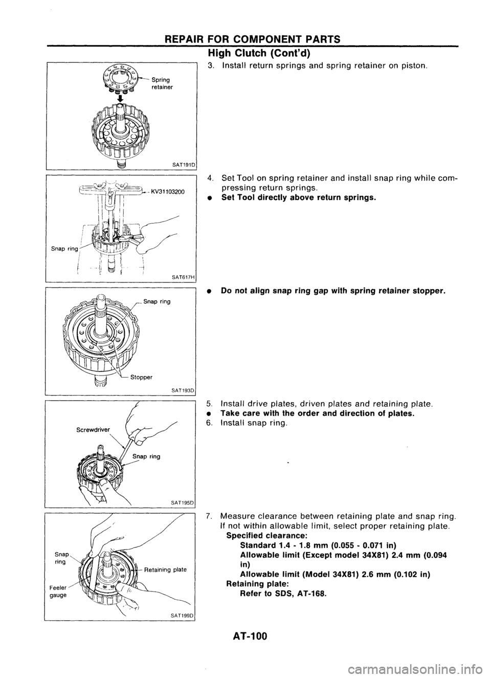
3. Install returnsprings andspring retainer onpiston.
- Spring
retainer
Snap ring:
Snap ring
Feeler
gauge
SAT191D
4.Set Toolan springretainer andinstall snapringwhile com-
pressing returnsprings.
• Set Tool directly abovereturnsprings.
--j
I
SAT617H
•Donot align snapringgapwith spring retainer stopper.
Snap ring
SAT1930
5.Install
drive
plates,
driven
platesandretaining plate.
• Take carewiththeorder anddirection ofplates.
6. Install snapring.
7. Measure clearance betweenretaining plateandsnap ring.
If not within allowable limit,select proper retaining plate.
Specified clearance:
Standard 1.4-1.8 mm {O.055 •0.071 in}
Allowable limit{Except model34X81} 2.4mm {O.094
in}
Allowable limit(Model 34X81)2.6mm (0.102 in)
Retaining plate:
Refer toSOS, AT-168.
SAT1990
AT-100