NISSAN ALMERA N15 1995 Manual Online
ALMERA N15 1995
NISSAN
NISSAN
https://www.carmanualsonline.info/img/5/57349/w960_57349-0.png
NISSAN ALMERA N15 1995 Manual Online
Trending: Lamp, battery location, key battery, service schedule, Fuel pressure regulato, spark plugs, EL-136
Page 81 of 1701
REPAIRFORCOMPONENT PARTS
Control ValveAssembly (Cont'd)
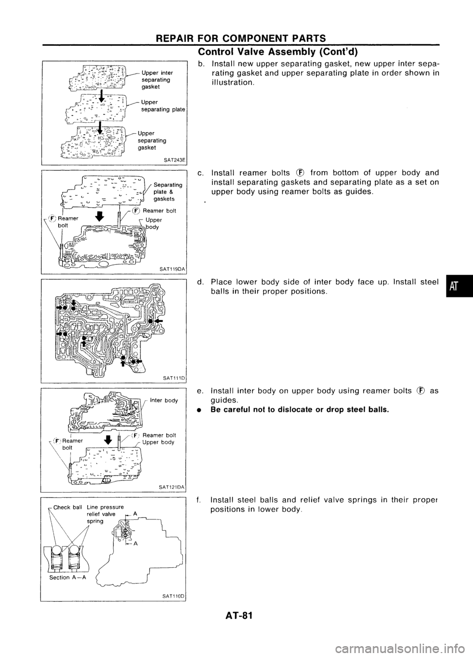
b. Install newupper separating gasket,newupper intersepa-
rating gasket andupper separating plateinorder shown in
illustration.
Upper
separating
gasket
SAT243E
Section A-ALine
pressure
relief valve
spring Separating
plate
&
gaskets
SAT119DA
Inter body
SAT121DA
SAT110D
c.
Install reamer bolts
(!)
from bottom ofupper bodyand
install separating gasketsandseparating plateasaset on
upper bodyusing reamer boltsasguides.
d. Place lower bodysideofinter body faceup.Install steel•
balls intheir proper positions.
e. Install interbody onupper bodyusing reamer bolts
(!)
as
guides.
• Becareful nottodislocate ordrop steel balls.
f. Install steelballsandrelief valve springs intheir proper
positions inlower body.
AT-81
Page 82 of 1701
Lowerseparating
gasket REPAIR
FORCOMPONENT PARTS
Control ValveAssembly (Cont'd)
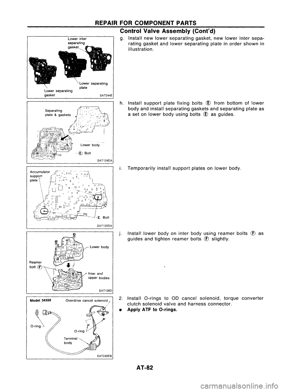
g. Install newlower separating gasket,newlower intersepa-
rating gasket andlower separating plateinorder shown in
illustration.
Lower separating
plate
SAT244E
Separating
plate &gaskets
Lowerbody
> (~)
Boit
SAT124DA
h.
Install support platefixing bolts
CID
from bottom oflower
body andinstall separating gasketsandseparating plateas
a set onlower bodyusing bolts
CID
asguides.
SAT125DA
i.
Temporarily installsupport platesonlower body.
Model 34X68 Lower
body
Inter and
upper bodies
SAT126D
Overdrive cancelsolenoid 7
.'
j.
Install lowerbodyoninter body using reamer bolts
(f)
as
guides andtighten reamer bolts
(f)
slightly.
2. Install a-rings toaD cancel solenoid, torqueconverter
clutch solenoid valveandharness connector.
• Apply ATF
toO-rings.
AT-82
Page 83 of 1701
REPAIRFORCOMPONENT PARTS
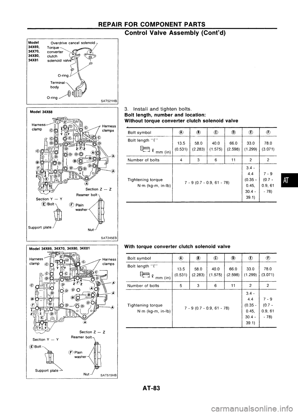
Control ValveAssembly (Cont'd)
Model
34X69, 34X70,
34X80, 34X81 Overdrive
cancelsolenoid
Torque~ converter
clutch
'0
solenoid valv~
'"
o_rin~
Terminal
0
body
O-ring~
l\
SAT521HB
Section Z- Z
Reamer bolt
Model
34X68
•
Bolt
symbol
@
@
@
@
(!)
ffi
Bolt length "C"
13.558.0 40.0 66.0
33.078.0
~ Q
mm(in)
(0.531)
(2.283)(1.575) (2.598)(1.299)
(3.071)
Number ofbolts
4
3611
22
3.4 -
4.4 7-9
Tightening torque
7-9 (0.7 -0.9, 61-78) (0.35
-(0.7 -
N'm (kg-m, in-Ib)
0.45,
0.9,61
30.4 - -78)
39.1)
3.
Install andtighten bolts.
Bolt length, number andlocation:
Without torqueconverter clutchsolenoid valve
/
Nut
(:E)
Plain
washer
Section
y- y
@Bolt~
Support plate
r
SAT245EB
Section
y- y
Section
Z- Z
Reamer bolt With
torque converter clutchsolenoid valve
Bolt symbol
@
@
@
@
(!)
ffi
Bolt length "C"
13.558.0
40.0 66.033.0
78.0
~ Q
mm (in)
(0.531)
(2.283)
(1.575) (2.598)(1.299)
(3.071)
Number ofbolts
536
11 2
2
3.4 -
4.4 7-9
Tightening torque
7-9 (0.7 -0.9, 61-78) (0.35
-(0.7 -
N'm (kg-m, in-Ib)
0.45,
0.9,61
30.4 --
78)
39.1)
(ElBolt -
. S"PP~
en
Plain
washer
AT-83
Page 84 of 1701
REPAIRFORCOMPONENT PARTS
Control ValveAssembly (Cont'd)
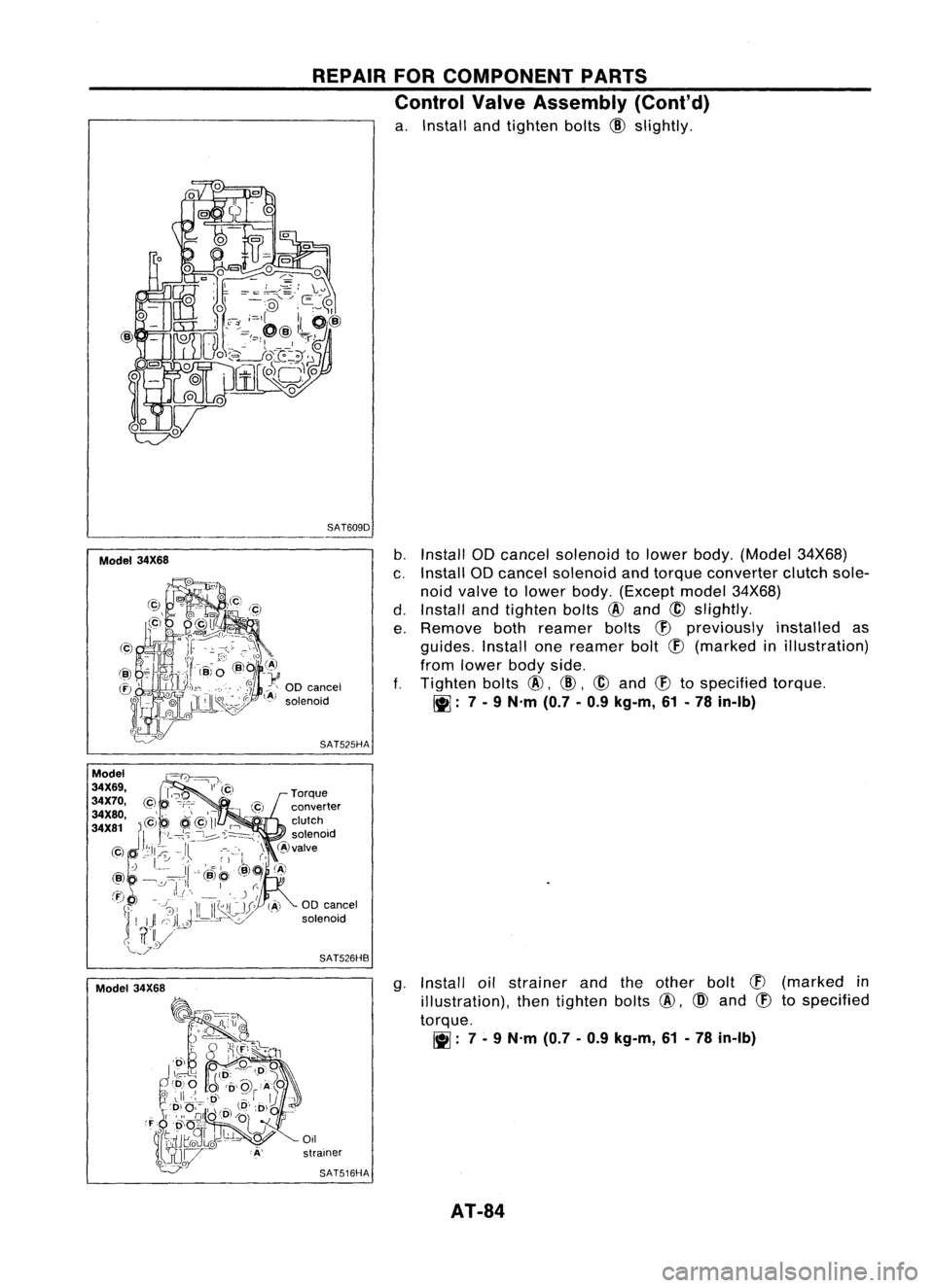
a. Install andtighten bolts
@
slightly.
SAT609D
Model 34X68
b.
Install ODcancel solenoid tolower body.(Model 34X68)
c. Install ODcancel solenoid andtorque converter clutchsole-
noid valve tolower body.(Except model34X68)
d. Install andtighten bolts
@
and
@
slightly.
e. Remove bothreamer bolts
(f)
previously installedas
guides. Installonereamer bolt
(f)
(marked inillustration)
from lower bodyside.
f.
Tighten bolts
@,
@,
@
and
(f)
tospecified torque.
~: 7-
9 N'm (0.7-0.9 kg-m, 61-78 in-Ib)
SAT525HA
00 cancel
solenoid
SAT526HB
g.Install oilstrainer andtheother bolt
CB
(marked in
illustration), thentighten bolts
@,
@
and
CB
tospecified
torque.
~: 7-
9 N'm (0.7-0.9 kg-m, 61-78 in-Ib)
Oil
strainer
SAT516HA
AT-84
Page 85 of 1701
Model34X69, 34X70, 34X80,34X81 REPAIR
FORCOMPONENT PARTS
Control ValveAssembly (Cant'd)
Model 34X68
Model
34X69,
34X70,
34X80,
34X81
Model
34X68
Model
34X69,
34X70,
34X80,
34X81
h,
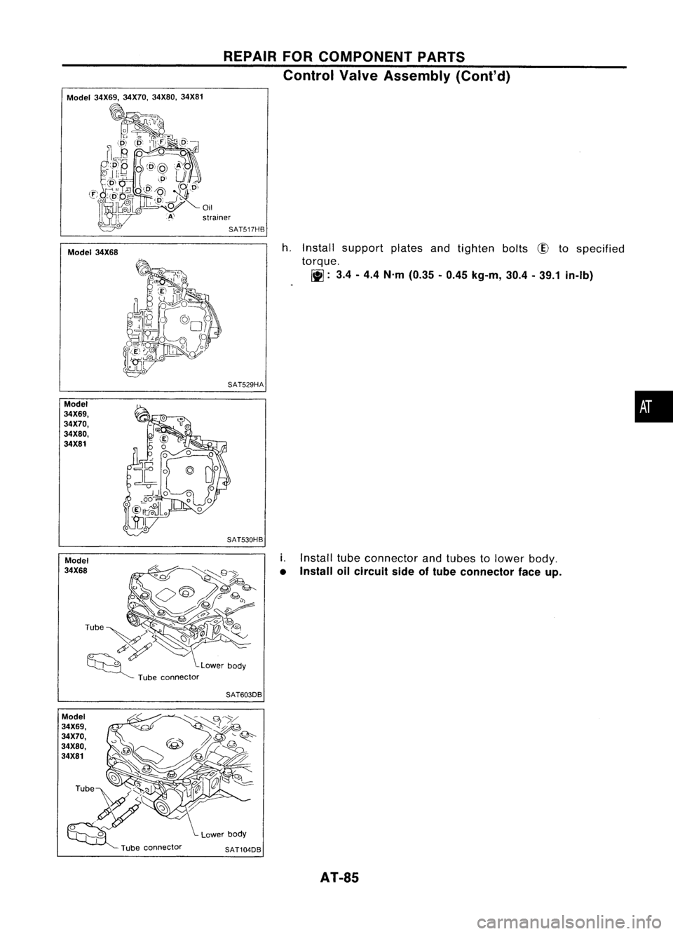
Install support platesandtighten bolts
CID
tospecified
torque.
[j]:
3.4-4.4 N'm (0.35 -0.45 kg-m, 30.4-39.1 in-Ib)
SAT529HA
i.
Install tubeconnector andtubes tolower body,
• Install oilcircuit sideoftube connector faceup.
SAT603DB
SAT104DB
AT-8S
•
Page 86 of 1701
REPAIRFORCOMPONENT PARTS
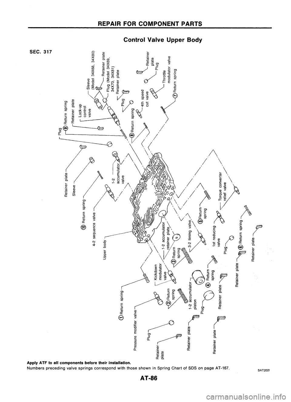
Control ValveUpper Body
SEC. 317
OJ
Ql
c:
Cil
.~
c.
(J)
iii
>
u
c:
c: c:
00
Z
~
-J
u
>
Ql
c:~
5
~
>
a:
Ql
@
U
c:
Ql
::J
0-
Ql
(J)
C\I
.;.
iii
0.
0.
::>
OJ
c:
';:
iit
E
::J
~
a:
e
(I)
Cil
c.
iii
c:
'19
Ql
a:
2
co
c.
iii
c:
yg
Ql
a:
Apply ATFtoall components beforetheirinstallation.
Numbers preceding valvesprings correspond withthose shown inSpring ChartofSDS onpage AT-167,
AT-86
SAT2021
Page 87 of 1701
REPAIRFORCOMPONENT PARTS
Control ValveUpper Body(Cont'd)
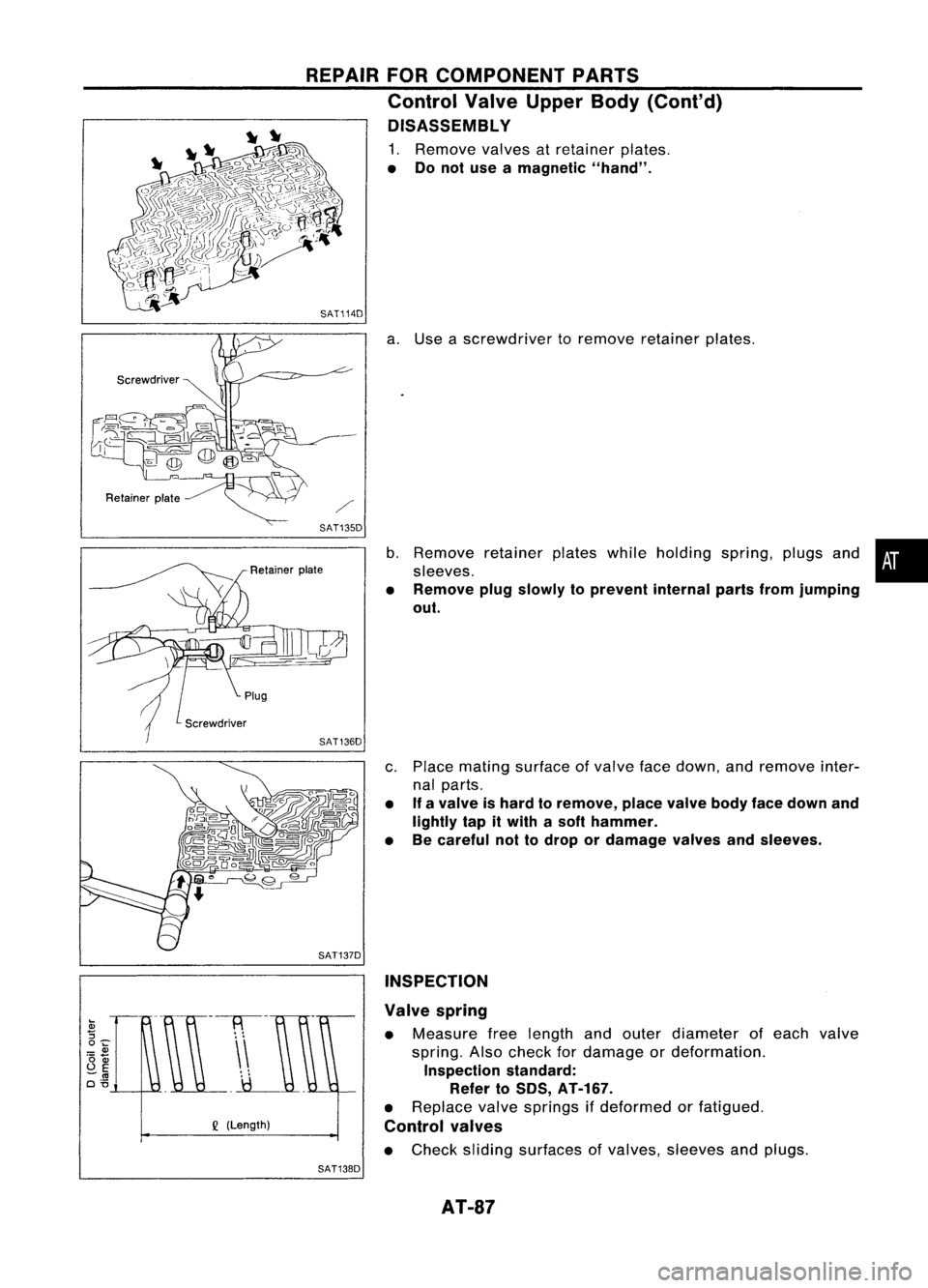
DISASSEMBL Y
1. Remove valvesatretainer plates.
• Donot use amagnetic "hand".
SAT114D
a.Use ascrewdriver toremove retainer plates.
SAT135D
b.Remove retainerplateswhileholding spring,plugsand•
sleeves.
• Remove plugslowly toprevent internalpartsfromjumping
out.
c. Place mating surface ofvalve facedown, andremove inter-
nal parts.
• If
avalve ishard toremove, placevalvebodyfacedown and
lightly tapitwith asoft hammer.
• Becareful nottodrop ordamage valvesandsleeves.
SAT137D INSPECTION
Q
(Length) Valve
spring
• Measure freelength andouter diameter ofeach valve
spring. Alsocheck fordamage ordeformation.
Inspection standard:
Refer to50S, AT-167.
• Replace valvesprings ifdeformed orfatigued.
Control valves
• Check sliding surfaces ofvalves, sleeves andplugs.
SAT138D
AT-87
Page 88 of 1701
REPAIRFORCOMPONENT PARTS
Control ValveUpper Body(Cont'd)
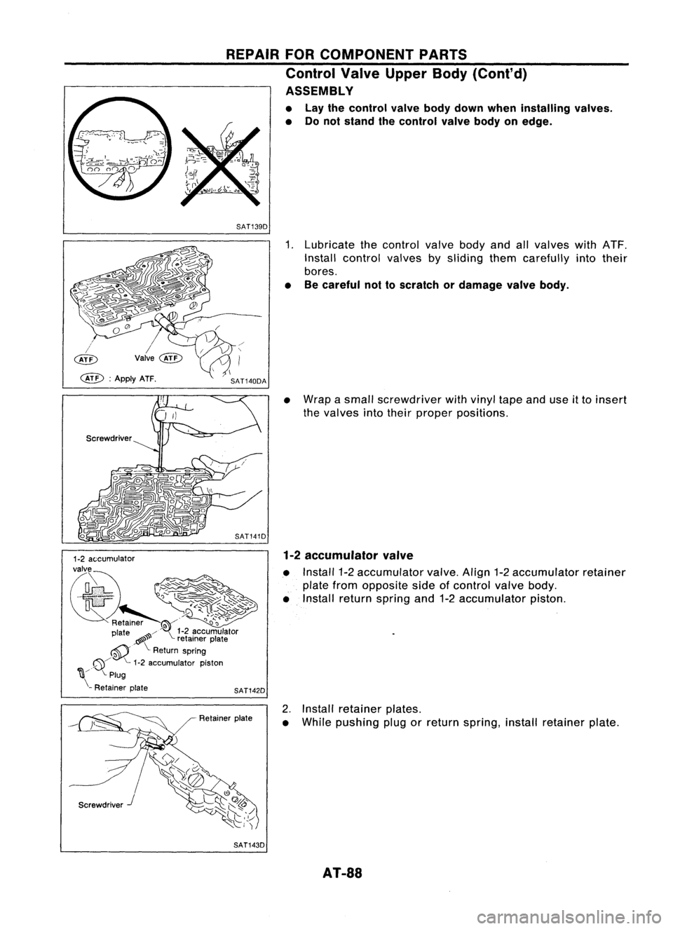
ASSEMBLY
• Lay thecontrol valvebodydown when installing valves.
• Donot stand thecontrol valvebodyonedge.
SAT139D
SAT141D
Screwdriver
Screwdriver J SAT142D
Retainer plate
SAT143D
1.
Lubricate thecontrol
valve
bodyandall
valves
withATF.
Install control valvesbysliding themcarefully intotheir
bores.
• Becareful nottoscratch ordamage valvebody.
• Wrap asmall screwdriver with
vinyl
tapeanduseitto insert
the valves intotheir proper positions.
1-2 accumulator valve
• Install 1-2accumulator
valve.
Align1-2accumulator retainer
plate fromopposite sideofcontrol
valve
body.
• Install return spring and1-2accumulator piston.
2. Install retainer plates.
• While pushing plugorreturn spring, installretainer plate.
AT-SS
Page 89 of 1701
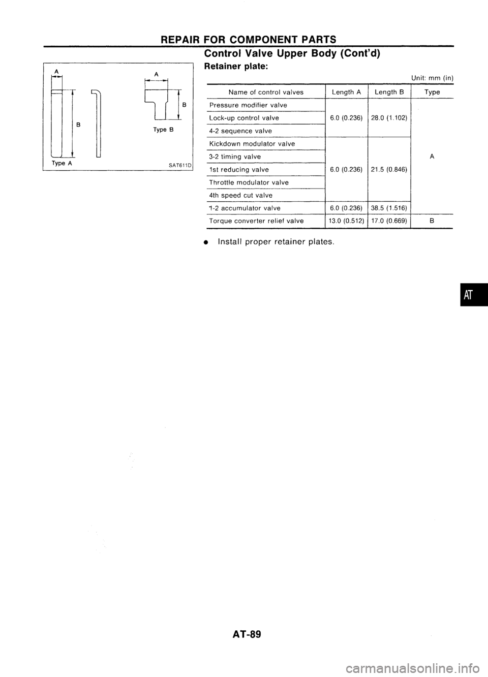
Unit:mm(in)
Name ofcontrol valves Length
ALength B Type
Pressure modifiervalve
Lock-up controlvalve 6.0
(0.236) 28.0(1.102)
4-2 sequence valve
Kickdown modulator valve
3-2 timing valve A
1st reducing valve 6.0
(0.236) 21.5(0.846)
Throttle modulator valve
4th speed cutvalve
1-2 accumulator valve 6.0
(0.236) 38.5(1516)
Torque converter reliefvalve 13.0(0.512) 17.0(0.669) B
SAT611D
REPAIR
FORCOMPONENT PARTS
Control ValveUpper Body(Cont'd)
Retainer plate:
Type B
A
E{1}
B
A
Type A
•Install proper retainer plates.
•
AT-89
Page 90 of 1701
SEC.317
~
o
.0
REPAIR
FORCOMPONENT PARTS
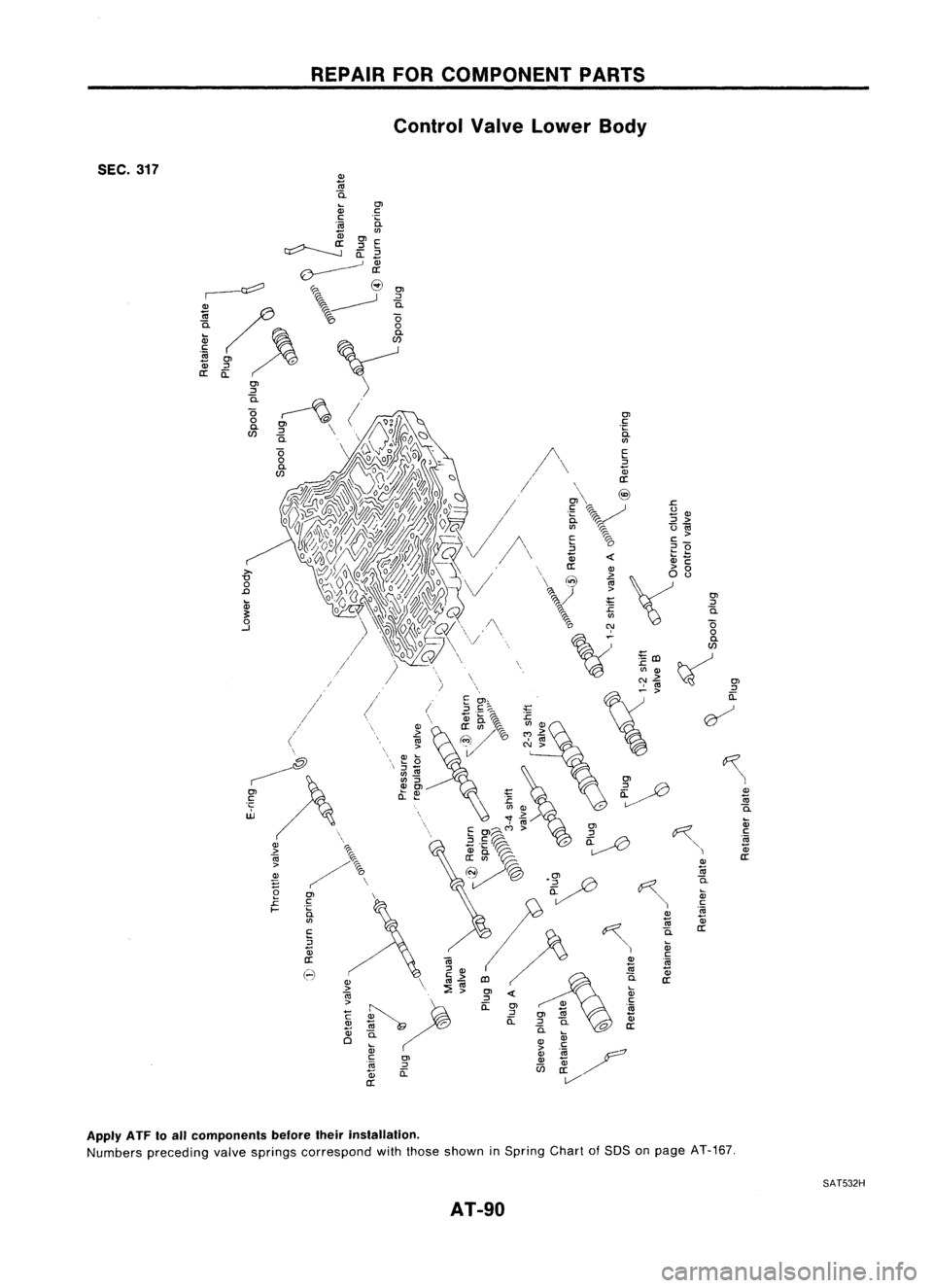
Control ValveLower Body
Ol
::>
i5.
o
o
a.
W
~Ol
::>
a:
~
Cll
m
i5.
Q;
c
'OJ
a;
a:
Apply ATFtoall components beforetheirinstallation.
Numbers preceding valvesprings correspond withthose shown inSpring ChartofSOS onpage AT-167.
AT-gO
SAT532H
Trending: service schedule, heater, trunk, Color, fog light, fuel, parking brake
