NISSAN ALMERA N16 2003 Electronic Repair Manual
ALMERA N16 2003
NISSAN
NISSAN
https://www.carmanualsonline.info/img/5/57350/w960_57350-0.png
NISSAN ALMERA N16 2003 Electronic Repair Manual
Trending: oil pressure, steering wheel adjustment, climate control, SRS HARNESS, battery location, service interval, Tail lamps
Page 2281 of 3189
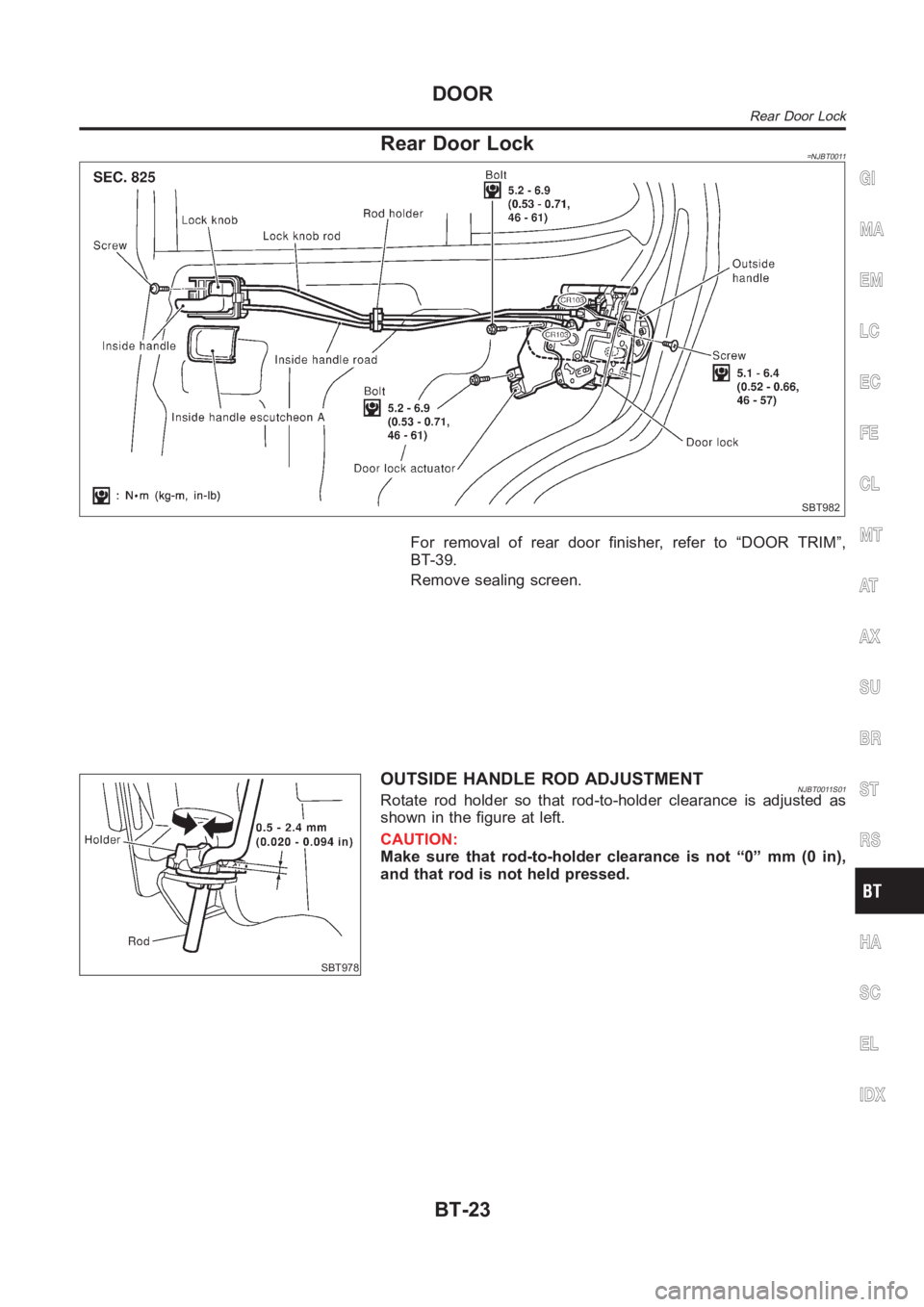
Rear Door Lock=NJBT0011
SBT982
For removal of rear door finisher, refer to “DOOR TRIM”,
BT-39.
Remove sealing screen.
SBT978
OUTSIDE HANDLE ROD ADJUSTMENTNJBT0011S01Rotate rod holder so that rod-to-holder clearance is adjusted as
shown in the figure at left.
CAUTION:
Make sure that rod-to-holder clearance is not “0” mm (0 in),
and that rod is not held pressed.
GI
MA
EM
LC
EC
FE
CL
MT
AT
AX
SU
BR
ST
RS
HA
SC
EL
IDX
DOOR
Rear Door Lock
BT-23
Page 2282 of 3189
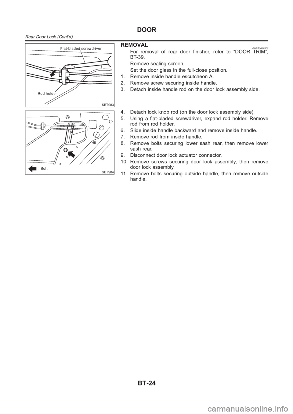
SBT983
REMOVAL=NJBT0011S02For removal of rear door finisher, refer to “DOOR TRIM”,
BT-39.
Remove sealing screen.
Set the door glass in the full-close position.
1. Remove inside handle escutcheon A.
2. Remove screw securing inside handle.
3. Detach inside handle rod on the door lock assembly side.
SBT984
4. Detach lock knob rod (on the door lock assembly side).
5. Using a flat-bladed screwdriver, expand rod holder. Remove
rod from rod holder.
6. Slide inside handle backward and remove inside handle.
7. Remove rod from inside handle.
8. Remove bolts securing lower sash rear, then remove lower
sash rear.
9. Disconnect door lock actuator connector.
10. Remove screws securing door lock assembly, then remove
door lock assembly.
11. Remove bolts securing outside handle, then remove outside
handle.
DOOR
Rear Door Lock (Cont’d)
BT-24
Page 2283 of 3189
Removal and InstallationNJBT0012CAUTION:
Disconnect ground terminal from battery in advance.
Disconnect air bag system line in advance.
Never tamper with or force air bag lid open, as this may adversely affect airbag performance.
Be careful not to scratch pad and other parts.GI
MA
EM
LC
EC
FE
CL
MT
AT
AX
SU
BR
ST
RS
HA
SC
EL
IDX
INSTRUMENT PANEL ASSEMBLY
Removal and Installation
BT-25
Page 2284 of 3189
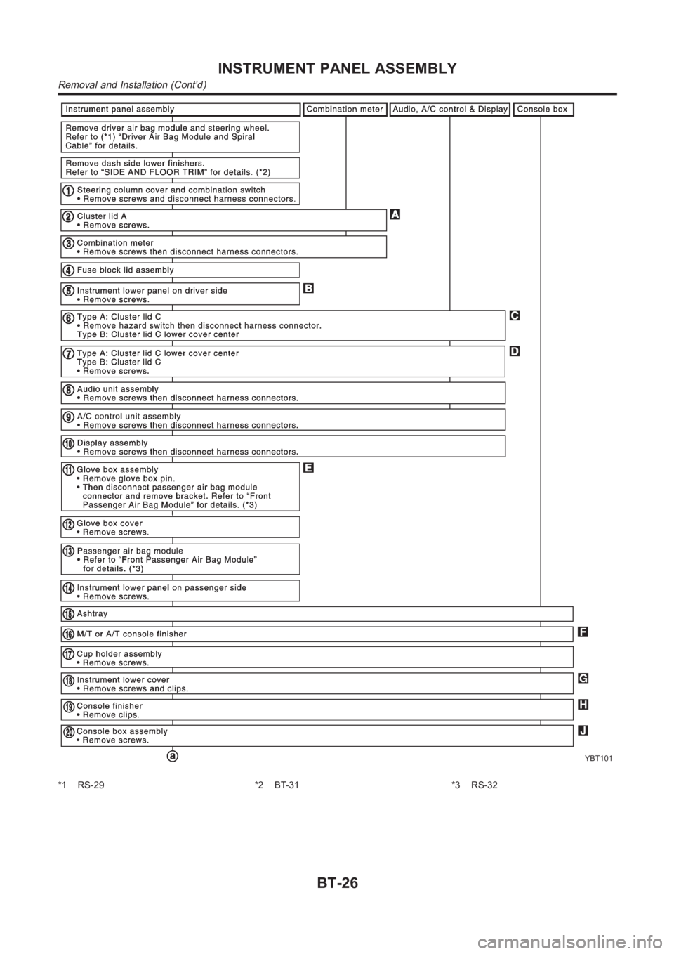
YBT101
*1 RS-29 *2 BT-31 *3 RS-32
INSTRUMENT PANEL ASSEMBLY
Removal and Installation (Cont’d)
BT-26
Page 2285 of 3189
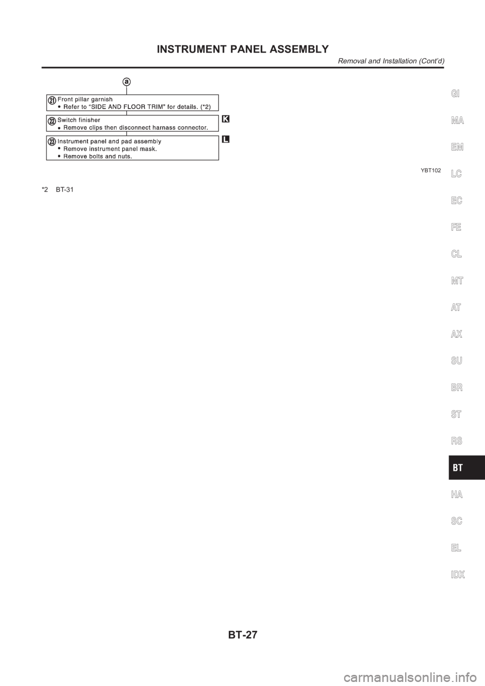
YBT102
*2 BT-31
GI
MA
EM
LC
EC
FE
CL
MT
AT
AX
SU
BR
ST
RS
HA
SC
EL
IDX
INSTRUMENT PANEL ASSEMBLY
Removal and Installation (Cont’d)
BT-27
Page 2286 of 3189
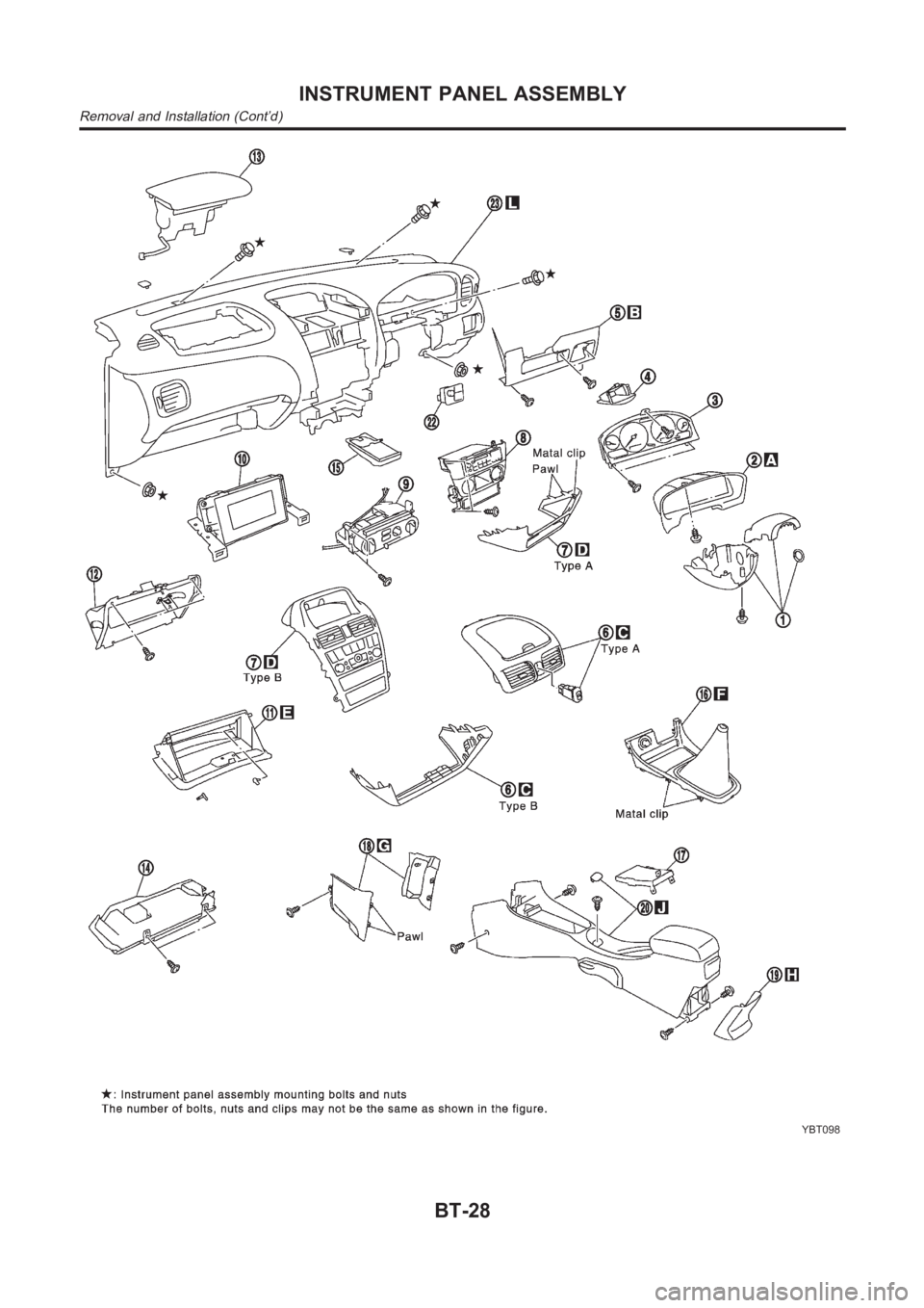
YBT098
INSTRUMENT PANEL ASSEMBLY
Removal and Installation (Cont’d)
BT-28
Page 2287 of 3189
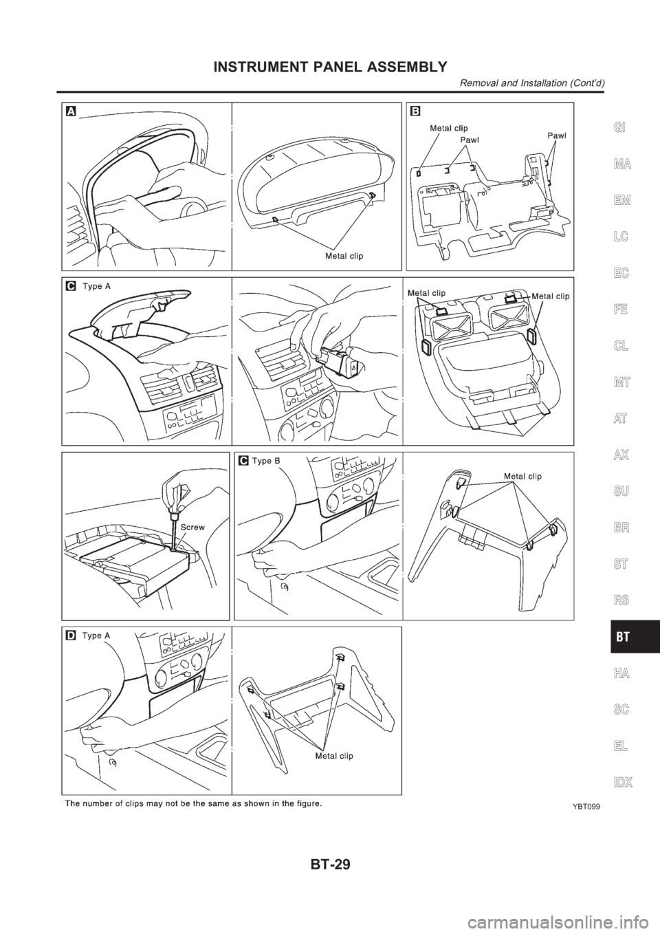
YBT099
GI
MA
EM
LC
EC
FE
CL
MT
AT
AX
SU
BR
ST
RS
HA
SC
EL
IDX
INSTRUMENT PANEL ASSEMBLY
Removal and Installation (Cont’d)
BT-29
Page 2288 of 3189
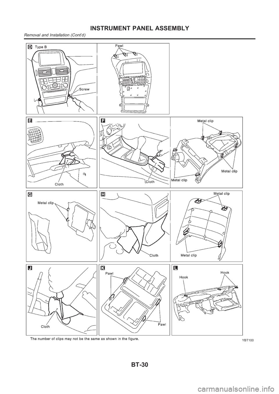
YBT100
INSTRUMENT PANEL ASSEMBLY
Removal and Installation (Cont’d)
BT-30
Page 2289 of 3189
Removal and InstallationNJBT0013SEDANNJBT0013S01CAUTION:
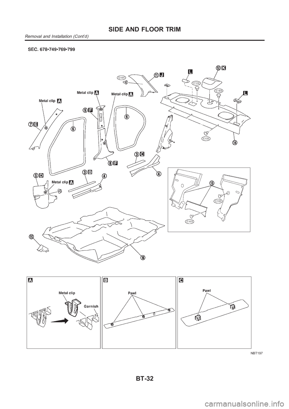
Wrap the tip of flat-bladed screwdriver with a cloth when removing metal clips from garnishes.
1. Remove front and rear seats. Refer to “FRONT SEAT” and “REAR SEAT” for details, BT-56 and BT-59.
2. Remove front and rear seat belts. Refer to RS-5 and RS-11, “Front Seat Belt” and “Rear Seat Belt” for
details.
3. Remove front and rear outer kicking plates.
4. Remove front and rear inner kicking plates.
5. Remove dash side finishers.
6. Remove front and rear body side welts.
7. Remove front pillar garnishes.
8. Remove center pillar lower garnishes.
9. Remove center pillar upper garnishes.
10. Remove rear seat back finishers.
11. Remove rear pillar finishers.
12. Remove high-mounted stop lamp. (Models without rear air spoiler)
13. Remove seat back center and side finishers.
14. Remove rear parcel shelf finisher.
15. Remove hoot rest.
16. Remove floor carpet.
GI
MA
EM
LC
EC
FE
CL
MT
AT
AX
SU
BR
ST
RS
HA
SC
EL
IDX
SIDE AND FLOOR TRIM
Removal and Installation
BT-31
Page 2290 of 3189
NBT197
SIDE AND FLOOR TRIM
Removal and Installation (Cont’d)
BT-32
Trending: smart entrance, steering wheel, recommended fluids, coolant, fuel cap release, turn signal, p1251
