NISSAN ALMERA TINO 2001 Service Repair Manual
ALMERA TINO 2001
NISSAN
NISSAN
https://www.carmanualsonline.info/img/5/57352/w960_57352-0.png
NISSAN ALMERA TINO 2001 Service Repair Manual
Trending: battery replacement, ABS, suspension, roof rack, heater, charging, length
Page 1351 of 3051
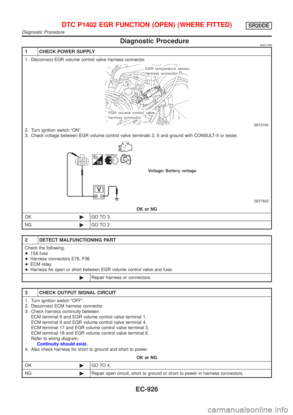
Diagnostic ProcedureNLEC1639
1 CHECK POWER SUPPLY
1. Disconnect EGR volume control valve harness connector.
SEF216X
2. Turn ignition switch ªONº.
3. Check voltage between EGR volume control valve terminals 2, 5 and ground with CONSULT-II or tester.
SEF782Z
OK or NG
OK©GO TO 3.
NG©GO TO 2.
2 DETECT MALFUNCTIONING PART
Check the following.
+15A fuse
+Harness connectors E76, F36
+ECM relay
+Harness for open or short between EGR volume control valve and fuse.
©Repair harness or connectors.
3 CHECK OUTPUT SIGNAL CIRCUIT
1. Turn ignition switch ªOFFº.
2. Disconnect ECM harness connector.
3. Check harness continuity between
ECM terminal 8 and EGR volume control valve terminal 1,
ECM terminal 9 and EGR volume control valve terminal 4,
ECM terminal 17 and EGR volume control valve terminal 3,
ECM terminal 18 and EGR volume control valve terminal 6.
Refer to wiring diagram.
Continuity should exist.
4. Also check harness for short to ground and short to power.
OK or NG
OK©GO TO 4.
NG©Repair open circuit, short to ground or short to power in harness connectors.
DTC P1402 EGR FUNCTION (OPEN) (WHERE FITTED)SR20DE
Diagnostic Procedure
EC-926
Page 1352 of 3051
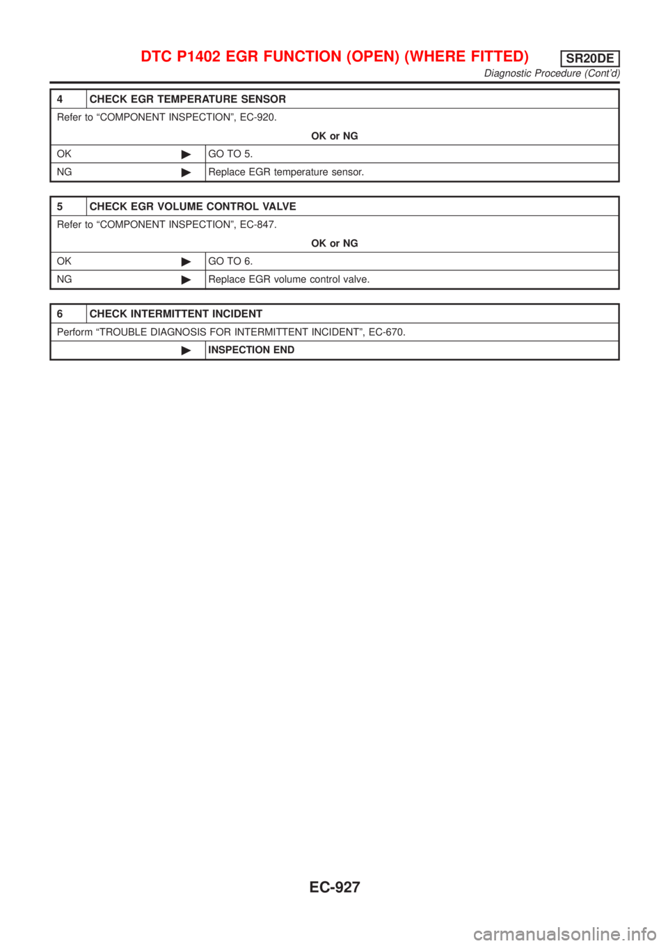
4 CHECK EGR TEMPERATURE SENSOR
Refer to ªCOMPONENT INSPECTIONº, EC-920.
OK or NG
OK©GO TO 5.
NG©Replace EGR temperature sensor.
5 CHECK EGR VOLUME CONTROL VALVE
Refer to ªCOMPONENT INSPECTIONº, EC-847.
OK or NG
OK©GO TO 6.
NG©Replace EGR volume control valve.
6 CHECK INTERMITTENT INCIDENT
Perform ªTROUBLE DIAGNOSIS FOR INTERMITTENT INCIDENTº, EC-670.
©INSPECTION END
DTC P1402 EGR FUNCTION (OPEN) (WHERE FITTED)SR20DE
Diagnostic Procedure (Cont'd)
EC-927
Page 1353 of 3051
System DescriptionNLEC1641The malfunction information related to CVT is transferred through the line (circuit) from TCM (Transmission
Control Module) to ECM. Therefore, be sure to erase the malfunction information such as DTC not only in TCM
(Transmission Control Module) but also ECM after the CVT related repair.
ECM Terminals and Reference ValueNLEC1642Specification data are reference values and are measured between each terminal and ground.
CAUTION:
Do not use ECM ground terminals when measuring input/output voltage. Doing so may result in dam-
age to the ECM's transistor. Use a ground other than ECM terminals, such as the ground.
TERMI-
NAL
NO.WIRE
COLORITEM CONDITION DATA (DC Voltage)
91 PU CVT check signal[Ignition switch ªONº]0 - Approximately 5V
On Board Diagnosis LogicNLEC1643
DTC No. Malfunction is detected when ... Check Items (Possible Cause)
P1605+An incorrect signal from TCM (Transmission Control
Module) is sent to ECM.+Harness or connectors
[The communication line circuit between ECM
and TCM (Transmission Control Module) is open
or shorted.]
+Dead (Weak) battery
+TCM (Transmission Control Module)
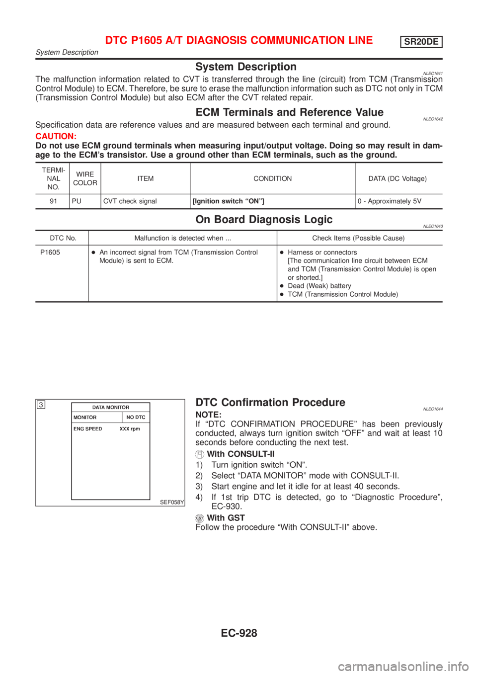
SEF058Y
DTC Confirmation ProcedureNLEC1644NOTE:
If ªDTC CONFIRMATION PROCEDUREº has been previously
conducted, always turn ignition switch ªOFFº and wait at least 10
seconds before conducting the next test.
With CONSULT-II
1) Turn ignition switch ªONº.
2) Select ªDATA MONITORº mode with CONSULT-II.
3) Start engine and let it idle for at least 40 seconds.
4) If 1st trip DTC is detected, go to ªDiagnostic Procedureº,
EC-930.
With GST
Follow the procedure ªWith CONSULT-IIº above.
DTC P1605 A/T DIAGNOSIS COMMUNICATION LINESR20DE
System Description
EC-928
Page 1354 of 3051
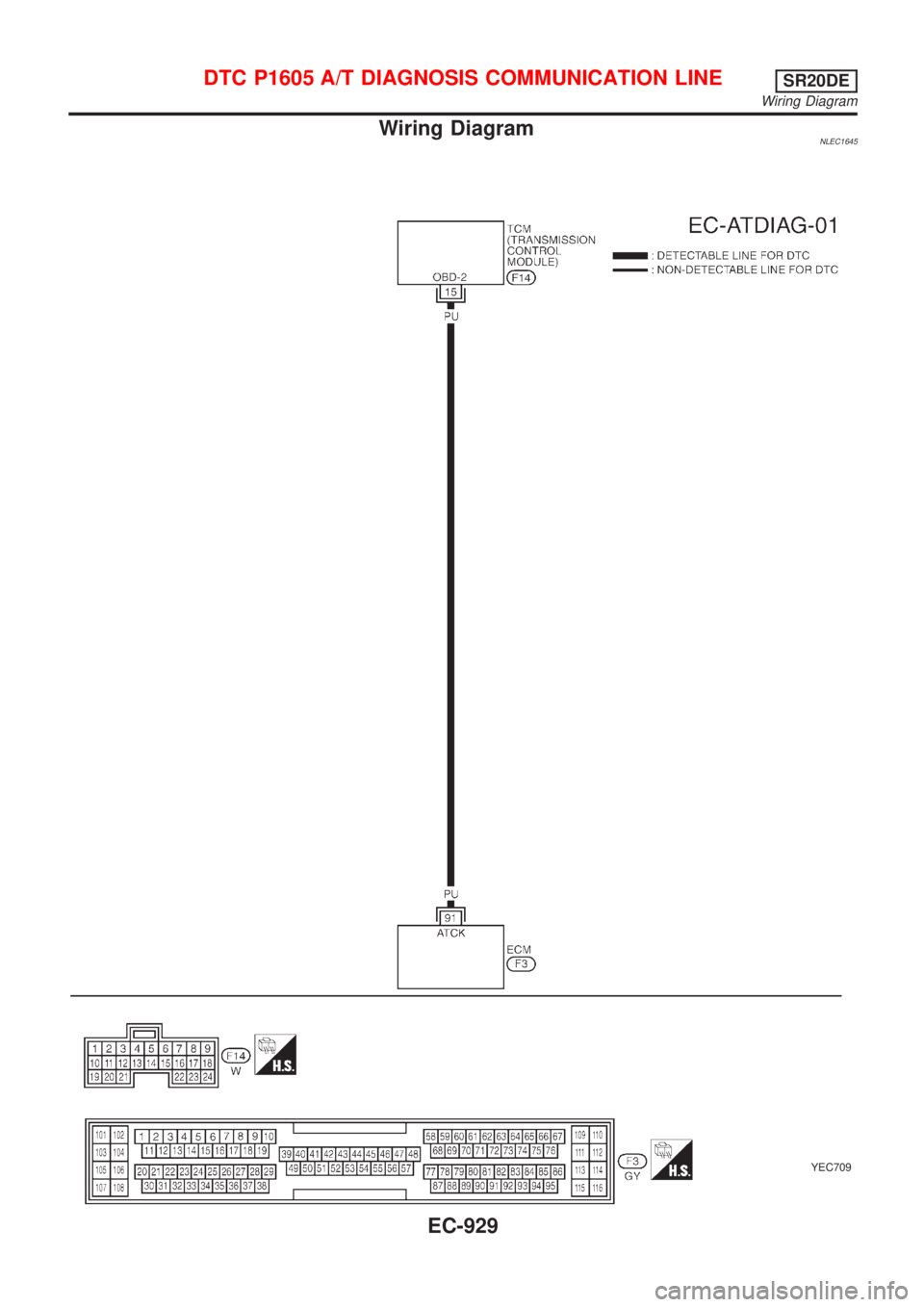
Wiring DiagramNLEC1645
YEC709
DTC P1605 A/T DIAGNOSIS COMMUNICATION LINESR20DE
Wiring Diagram
EC-929
Page 1355 of 3051
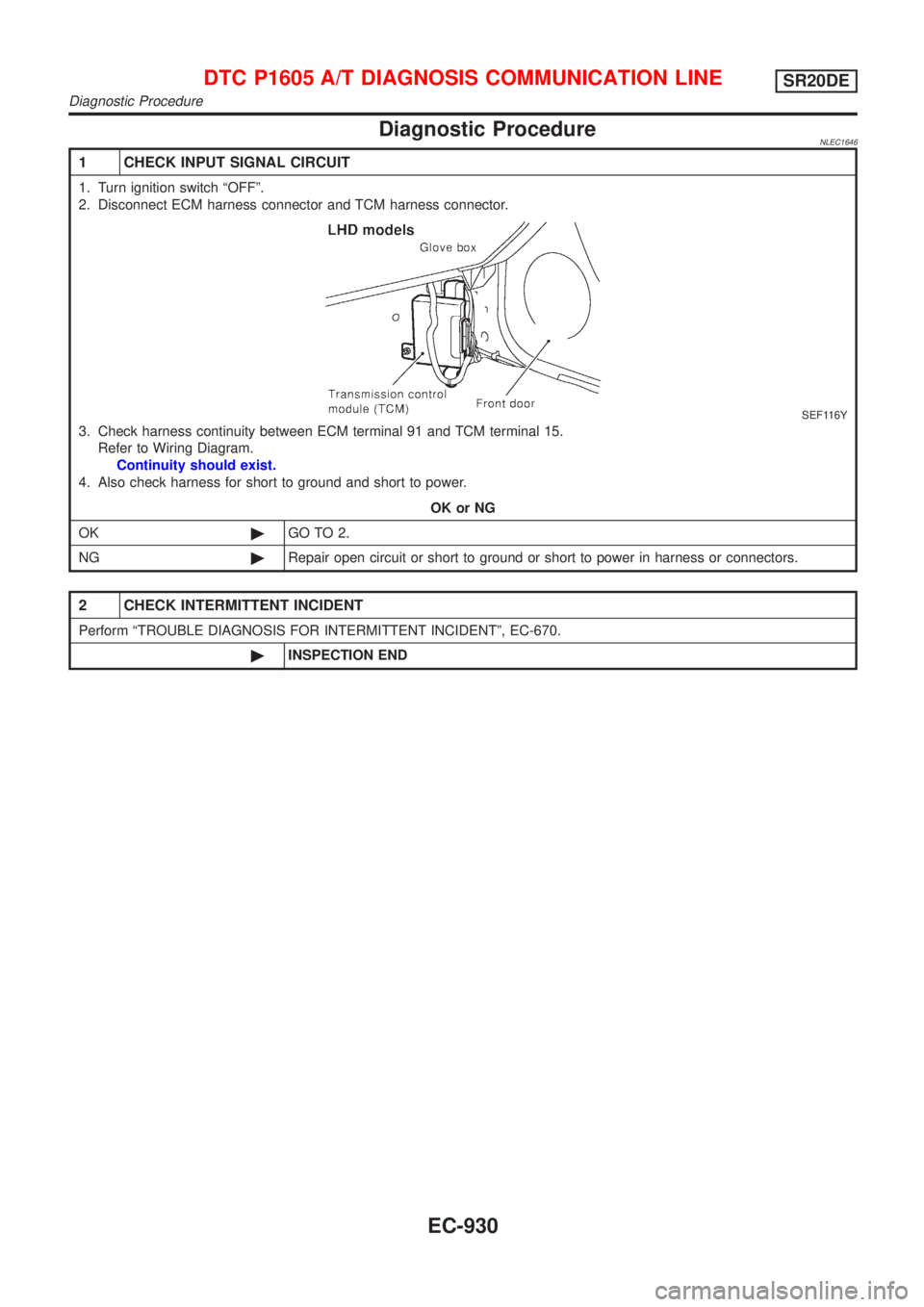
Diagnostic ProcedureNLEC1646
1 CHECK INPUT SIGNAL CIRCUIT
1. Turn ignition switch ªOFFº.
2. Disconnect ECM harness connector and TCM harness connector.
SEF116Y
3. Check harness continuity between ECM terminal 91 and TCM terminal 15.
Refer to Wiring Diagram.
Continuity should exist.
4. Also check harness for short to ground and short to power.
OK or NG
OK©GO TO 2.
NG©Repair open circuit or short to ground or short to power in harness or connectors.
2 CHECK INTERMITTENT INCIDENT
Perform ªTROUBLE DIAGNOSIS FOR INTERMITTENT INCIDENTº, EC-670.
©INSPECTION END
DTC P1605 A/T DIAGNOSIS COMMUNICATION LINESR20DE
Diagnostic Procedure
EC-930
Page 1356 of 3051
SEF781Z
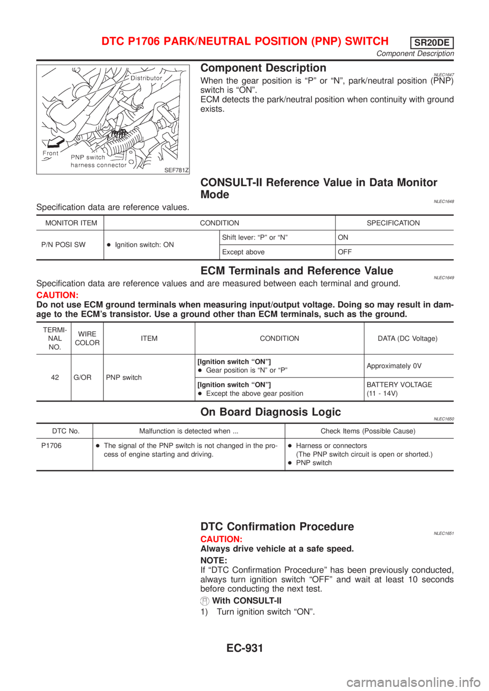
Component DescriptionNLEC1647When the gear position is ªPº or ªNº, park/neutral position (PNP)
switch is ªONº.
ECM detects the park/neutral position when continuity with ground
exists.
CONSULT-II Reference Value in Data Monitor
Mode
NLEC1648Specification data are reference values.
MONITOR ITEM CONDITION SPECIFICATION
P/N POSI SW+Ignition switch: ONShift lever: ªPº or ªNº ON
Except above OFF
ECM Terminals and Reference ValueNLEC1649Specification data are reference values and are measured between each terminal and ground.
CAUTION:
Do not use ECM ground terminals when measuring input/output voltage. Doing so may result in dam-
age to the ECM's transistor. Use a ground other than ECM terminals, such as the ground.
TERMI-
NAL
NO.WIRE
COLORITEM CONDITION DATA (DC Voltage)
42 G/OR PNP switch[Ignition switch ªONº]
+Gear position is ªNº or ªPºApproximately 0V
[Ignition switch ªONº]
+Except the above gear positionBATTERY VOLTAGE
(11 - 14V)
On Board Diagnosis LogicNLEC1650
DTC No. Malfunction is detected when ... Check Items (Possible Cause)
P1706+The signal of the PNP switch is not changed in the pro-
cess of engine starting and driving.+Harness or connectors
(The PNP switch circuit is open or shorted.)
+PNP switch
DTC Confirmation ProcedureNLEC1651CAUTION:
Always drive vehicle at a safe speed.
NOTE:
If ªDTC Confirmation Procedureº has been previously conducted,
always turn ignition switch ªOFFº and wait at least 10 seconds
before conducting the next test.
With CONSULT-II
1) Turn ignition switch ªONº.
DTC P1706 PARK/NEUTRAL POSITION (PNP) SWITCHSR20DE
Component Description
EC-931
Page 1357 of 3051
SEF213Y
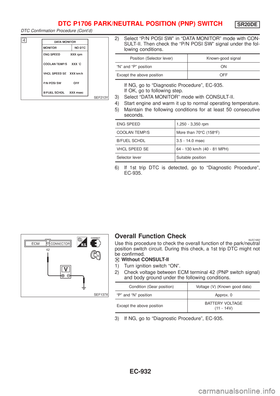
2) Select ªP/N POSI SWº in ªDATA MONITORº mode with CON-
SULT-II. Then check the ªP/N POSI SWº signal under the fol-
lowing conditions.
Position (Selector lever) Known-good signal
ªNº and ªPº position ON
Except the above position OFF
If NG, go to ªDiagnostic Procedureº, EC-935.
If OK, go to following step.
3) Select ªDATA MONITORº mode with CONSULT-II.
4) Start engine and warm it up to normal operating temperature.
5) Maintain the following conditions for at least 50 consecutive
seconds.
ENG SPEED 1,250 - 3,350 rpm
COOLAN TEMP/S More than 70ÉC (158ÉF)
B/FUEL SCHDL 3.5 - 14.0 msec
VHCL SPEED SE 64 - 130 km/h (40 - 81 MPH)
Selector lever Suitable position
6) If 1st trip DTC is detected, go to ªDiagnostic Procedureº,
EC-935.
SEF137X
Overall Function CheckNLEC1652Use this procedure to check the overall function of the park/neutral
position switch circuit. During this check, a 1st trip DTC might not
be confirmed.
Without CONSULT-II
1) Turn ignition switch ªONº.
2) Check voltage between ECM terminal 42 (PNP switch signal)
and body ground under the following conditions.
Condition (Gear position) Voltage (V) (Known good data)
ªPº and ªNº position Approx. 0
Except the above positionBATTERY VOLTAGE
(11 - 14V)
3) If NG, go to ªDiagnostic Procedureº, EC-935.
DTC P1706 PARK/NEUTRAL POSITION (PNP) SWITCHSR20DE
DTC Confirmation Procedure (Cont'd)
EC-932
Page 1358 of 3051
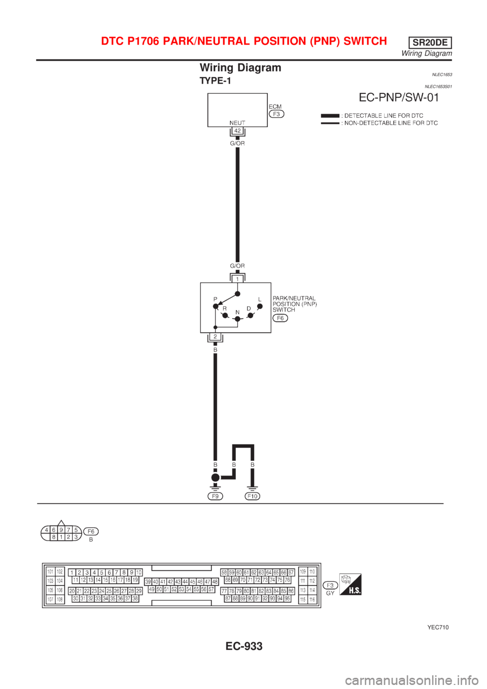
Wiring DiagramNLEC1653TYPE-1NLEC1653S01
YEC710
DTC P1706 PARK/NEUTRAL POSITION (PNP) SWITCHSR20DE
Wiring Diagram
EC-933
Page 1359 of 3051
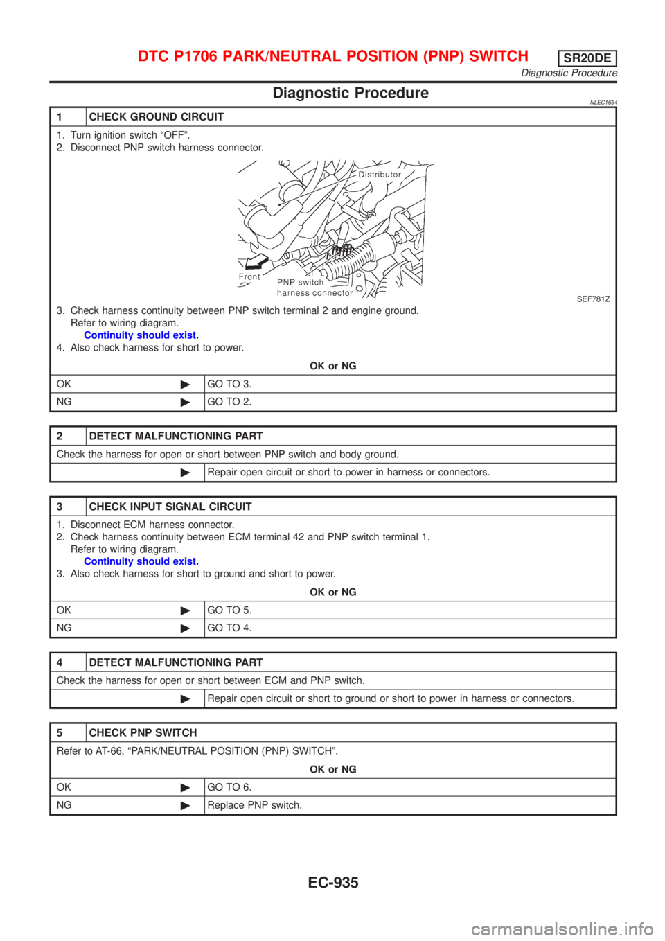
TYPE-2NLEC1653S02
YEC929
DTC P1706 PARK/NEUTRAL POSITION (PNP) SWITCHSR20DE
Wiring Diagram (Cont'd)
EC-934
Page 1360 of 3051
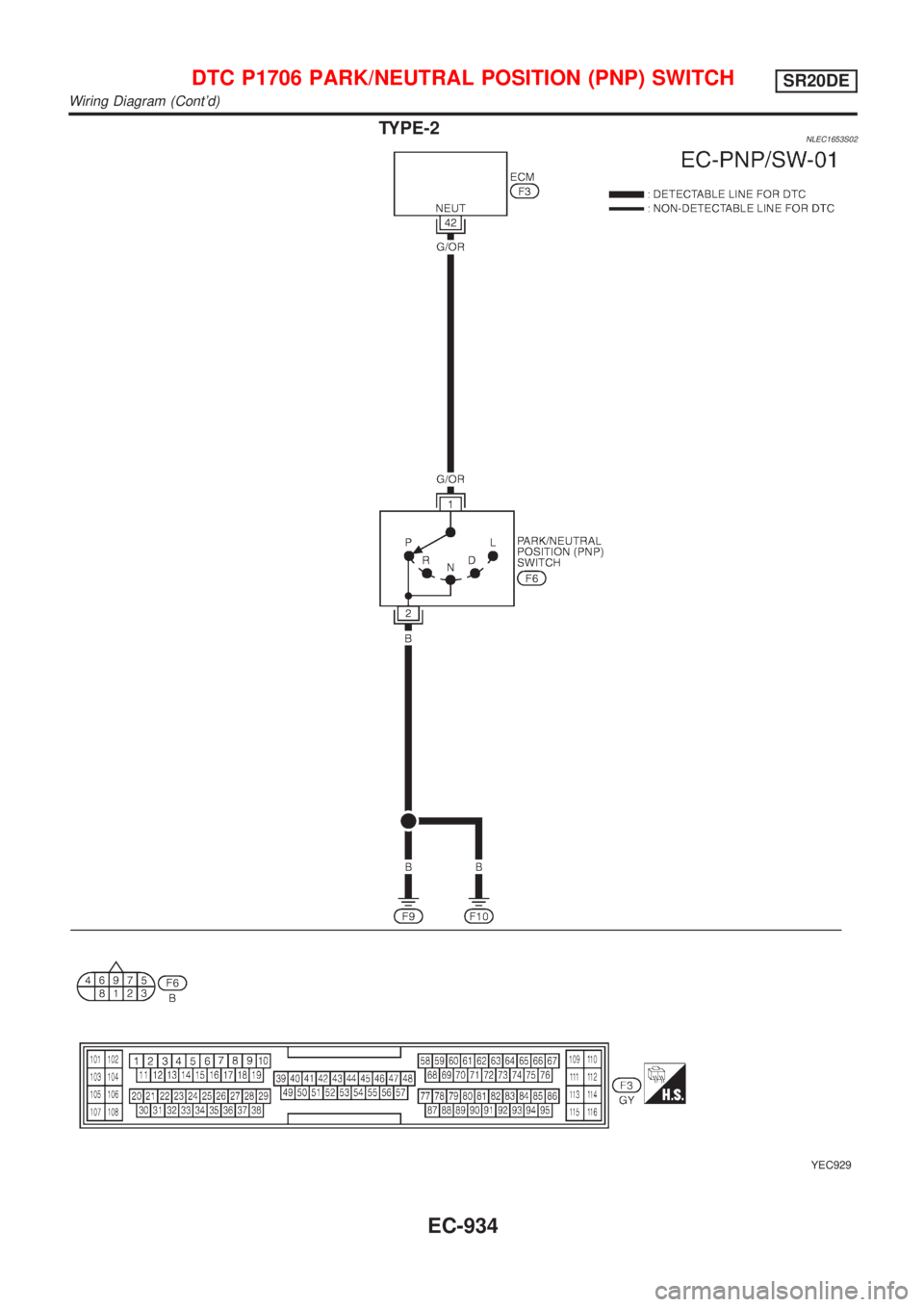
DiagnosticProcedure
1 CHEC KGROUN DCIRCUIT
SEF781Z
2 DETEC TMALFUNCTIONIN GPART
3 CHEC KINPU TSIGNA LCIRCUIT
4 DETEC TMALFUNCTIONIN GPART
5 CHEC KPN PSWITCH
Diagnostic Procedure
Trending: child lock, remote start, battery monitoring sensor, stop start, brake rotor, engine overheat, fuse

