NISSAN LATIO 2011 Service Repair Manual
Manufacturer: NISSAN, Model Year: 2011, Model line: LATIO, Model: NISSAN LATIO 2011Pages: 3787, PDF Size: 78.35 MB
Page 3211 of 3787
MA-40
< SERVICE INFORMATION >
CHASSIS AND BODY MAINTENANCE
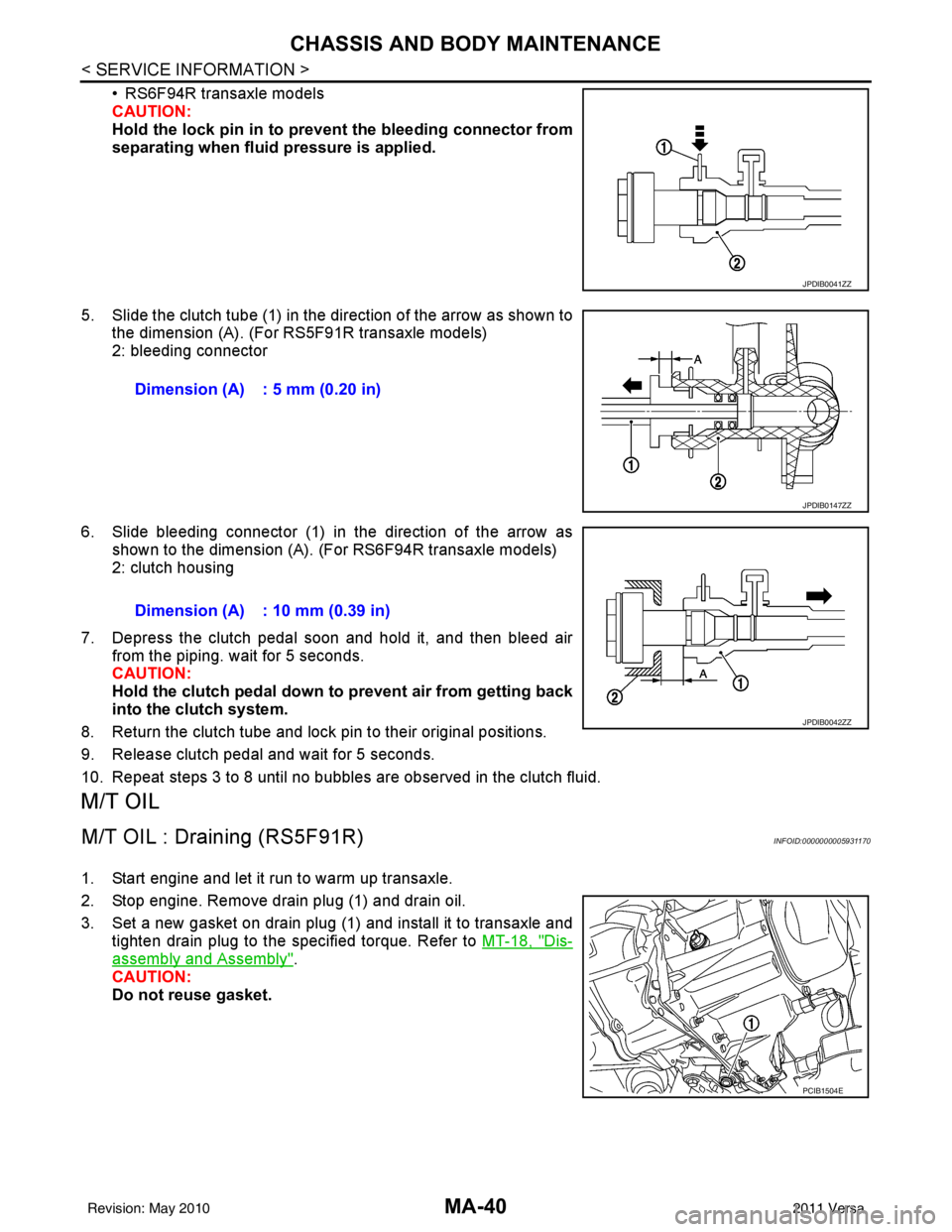
• RS6F94R transaxle models
CAUTION:
Hold the lock pin in to prevent the bleeding connector from
separating when fluid pressure is applied.
5. Slide the clutch tube (1) in the direction of the arrow as shown to the dimension (A). (For RS5F91R transaxle models)
2: bleeding connector
6. Slide bleeding connector (1) in the direction of the arrow as shown to the dimension (A). (For RS6F94R transaxle models)
2: clutch housing
7. Depress the clutch pedal soon and hold it, and then bleed air from the piping. wait for 5 seconds.
CAUTION:
Hold the clutch pedal down to prevent air from getting back
into the clutch system.
8. Return the clutch tube and lock pin to their original positions.
9. Release clutch pedal and wait for 5 seconds.
10. Repeat steps 3 to 8 until no bubbles are observed in the clutch fluid.
M/T OIL
M/T OIL : Draining (RS5F91R)INFOID:0000000005931170
1. Start engine and let it run to warm up transaxle.
2. Stop engine. Remove drain plug (1) and drain oil.
3. Set a new gasket on drain plug (1) and install it to transaxle and tighten drain plug to the specified torque. Refer to MT-18, "
Dis-
assembly and Assembly".
CAUTION:
Do not reuse gasket.
JPDIB0041ZZ
Dimension (A) : 5 mm (0.20 in)
JPDIB0147ZZ
Dimension (A) : 10 mm (0.39 in)
JPDIB0042ZZ
PCIB1504E
Revision: May 2010 2011 Versa
Page 3212 of 3787
CHASSIS AND BODY MAINTENANCEMA-41
< SERVICE INFORMATION >
C
DE
F
G H
I
J
K
M A
B
MA
N
O P
M/T OIL : Refilling (RS5F91R)INFOID:0000000005931171
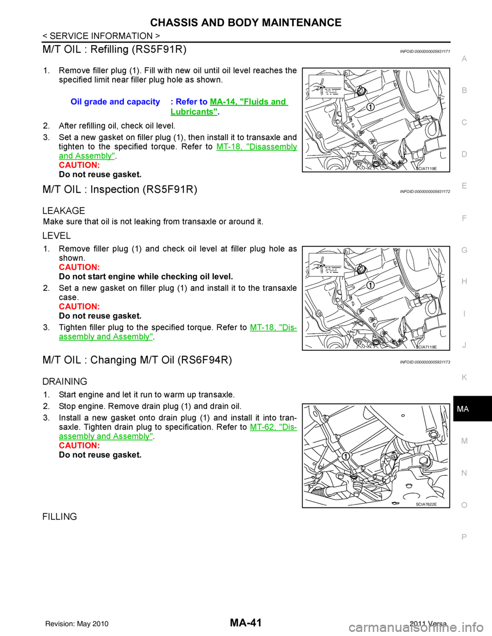
1. Remove filler plug (1). Fill with new oil until oil level reaches the specified limit near filler plug hole as shown.
2. After refilling oil, check oil level.
3. Set a new gasket on filler plug (1), then install it to transaxle and tighten to the specified torque. Refer to MT-18, "
Disassembly
and Assembly".
CAUTION:
Do not reuse gasket.
M/T OIL : Inspection (RS5F91R)INFOID:0000000005931172
LEAKAGE
Make sure that oil is not leaking from transaxle or around it.
LEVEL
1. Remove filler plug (1) and check oil level at filler plug hole as shown.
CAUTION:
Do not start engine while checking oil level.
2. Set a new gasket on filler plug (1) and install it to the transaxle case.
CAUTION:
Do not reuse gasket.
3. Tighten filler plug to the specified torque. Refer to MT-18, "
Dis-
assembly and Assembly".
M/T OIL : Changing M/T Oil (RS6F94R)INFOID:0000000005931173
DRAINING
1. Start engine and let it run to warm up transaxle.
2. Stop engine. Remove drain plug (1) and drain oil.
3. Install a new gasket onto drain plug (1) and install it into tran-
saxle. Tighten drain plug to specification. Refer to MT-62, "
Dis-
assembly and Assembly".
CAUTION:
Do not reuse gasket.
FILLING
Oil grade and capacity : Refer to MA-14, "Fluids and
Lubricants".
SCIA7119E
SCIA7119E
SCIA7622E
Revision: May 2010 2011 Versa
Page 3213 of 3787
MA-42
< SERVICE INFORMATION >
CHASSIS AND BODY MAINTENANCE
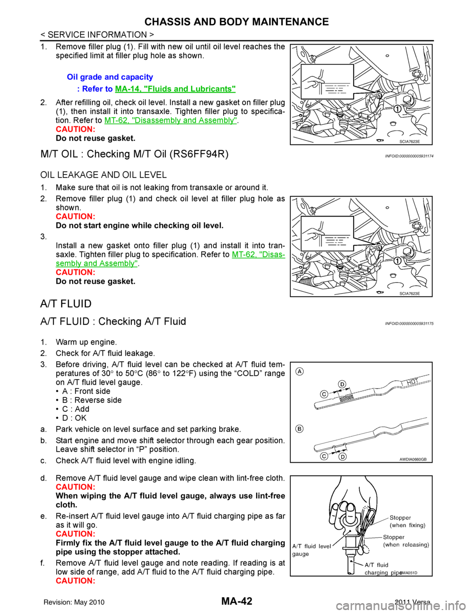
1. Remove filler plug (1). Fill with new oil until oil level reaches thespecified limit at filler plug hole as shown.
2. After refilling oil, check oil level. Install a new gasket on filler plug (1), then install it into transaxle. Tighten filler plug to specifica-
tion. Refer to MT-62, "
Disassembly and Assembly".
CAUTION:
Do not reuse gasket.
M/T OIL : Checking M/T Oil (RS6FF94R)INFOID:0000000005931174
OIL LEAKAGE AND OIL LEVEL
1. Make sure that oil is not leaking from transaxle or around it.
2. Remove filler plug (1) and check oil level at filler plug hole as shown.
CAUTION:
Do not start engine wh ile checking oil level.
3. Install a new gasket onto filler plug (1) and install it into tran-
saxle. Tighten filler plug to specification. Refer to MT-62, "
Disas-
sembly and Assembly".
CAUTION:
Do not reuse gasket.
A/T FLUID
A/T FLUID : Checking A/T FluidINFOID:0000000005931175
1. Warm up engine.
2. Check for A/T fluid leakage.
3. Before driving, A/T fluid level can be checked at A/T fluid tem- peratures of 30 ° to 50 °C (86° to 122° F) using the “COLD” range
on A/T fluid level gauge.
• A : Front side
• B : Reverse side
• C : Add
• D : OK
a. Park vehicle on level surface and set parking brake.
b. Start engine and move shift selector through each gear position. Leave shift selector in “P” position.
c. Check A/T fluid level with engine idling.
d. Remove A/T fluid level gauge and wipe clean with lint-free cloth. CAUTION:
When wiping the A/T fluid level gauge, always use lint-free
cloth.
e. Re-insert A/T fluid level gauge into A/T fluid charging pipe as far as it will go.
CAUTION:
Firmly fix the A/T fluid level gauge to the A/T fluid charging
pipe using the stopper attached.
f. Remove A/T fluid level gauge and note reading. If reading is at low side of range, add A/T fluid to the A/T fluid charging pipe.
CAUTION:Oil grade and capacity
: Refer to MA-14, "
Fluids and Lubricants"
SCIA7623E
SCIA7623E
AWDIA0660GB
SMA051D
Revision: May 2010 2011 Versa
Page 3214 of 3787
CHASSIS AND BODY MAINTENANCEMA-43
< SERVICE INFORMATION >
C
DE
F
G H
I
J
K
M A
B
MA
N
O P
Do not overfill.
4. Drive vehicle for approximately 5 minutes.
5. Re-check A/T fluid level at A/T fluid temperatures of 50° to 80 °C (122° to 176°F) using “HOT” range on A/
T fluid level gauge.
CAUTION:
• When wiping the A/T fluid level gauge, always use lint-free cloth.
• Firmly fix the A/T fluid level ga uge to the A/T fluid charging pipe using the stopper attached.
6. Check A/T fluid condition and make any necessary repairs. Refer to AT-51, "
Inspections Before Trouble
Diagnosis". If the A/T fluid contains frictional material (clutches, bands, etc.), or if the A/T is repaired, over-
hauled, or replaced, inspect and clean the A/T fluid cooler mounted in the radiator. Refer to AT-18, "
A/T
Fluid Cooler Cleaning".
7. Install the removed A/T fluid level gauge into the A/T fluid charging pipe. CAUTION:
Firmly fix the A/T fluid level gaug e to the A/T fluid charging pipe using the stopper attached.
A/T FLUID : Changing A/T FluidINFOID:0000000005931176
1. Warm up A/T fluid.
2. Stop engine.
3. Drain A/T fluid by removing the drain plug. Re install the drain plug to the specified torque.
CAUTION:
Do not reuse drain plug gasket.
4. Refill the transaxle with new specified A/T fluid through the A/T fluid charging pipe. Always refill the tran- saxle with the same volume of A/T fluid that was drained out.
5. Run engine at idle speed for 5 minutes.
6. Check A/T fluid level and condition. Refer to MA-42, "
A/T FLUID : Checking A/T Fluid".
WHEELS
WHEELS : AdjustmentINFOID:0000000006413331
BALANCING WHEELS (ADHESIVE WEIGHT TYPE)
Preparation Before Adjustment
Remove inner and outer balance weights from the r oad wheel using releasing agent, remove double-faced
adhesive tape from the road wheel.
CAUTION:
• Be careful not scratch the road wheel during removal.
• After removing double-faced adhesive tape, wipe clean traces of releasing agent from the road
wheel.
Wheel Balance Adjustment
• If a balancer machine has an adhesive weight mode setting, select the adhesive weight mode setting and skip Step 2. below. If a balancer machine only has the clip-on (rim flange) weight mode setting, follow Step 2.
to calculate the correct size adhesive weight.
1. Set road wheel on balancer machine using the cent er hole as a guide. Start the balancer machine.
2. For tire balance machines that only have a clip-on (ri m flange) weight mode setting, follow this step to cal-
culate the correct size adhesive weight to use. When inner and outer imbalance values are shown on the
balancer machine indicator, multiply outer imbalance value by 5/3 (1.67) to determine balance weight that
should be used. Select the outer balance weight with a value closest to the calculated value above and
install in to the designated outer position of, or at the designated angle in relation to the road wheel.
Drain plug: Refer to
AT-237, "
Component".
Fluid grade and capacity: Refer to MA-14
.
Revision: May 2010 2011 Versa
Page 3215 of 3787
MA-44
< SERVICE INFORMATION >
CHASSIS AND BODY MAINTENANCE
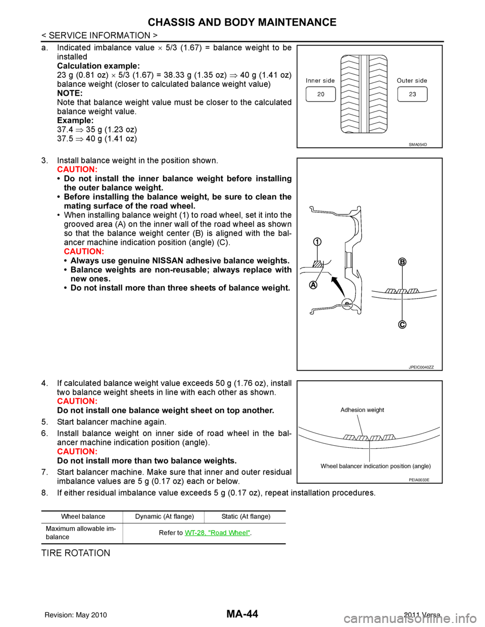
a. Indicated imbalance value × 5/3 (1.67) = balance weight to be
installed
Calculation example:
23 g (0.81 oz) × 5/3 (1.67) = 38.33 g (1.35 oz) ⇒ 40 g (1.41 oz)
balance weight (closer to calculated balance weight value)
NOTE:
Note that balance weight value must be closer to the calculated
balance weight value.
Example:
37.4 ⇒ 35 g (1.23 oz)
37.5 ⇒ 40 g (1.41 oz)
3. Install balance weight in the position shown. CAUTION:
• Do not install the inner bala nce weight before installing
the outer balance weight.
• Before installing the balance weight, be sure to clean the
mating surface of the road wheel.
• When installing balance weight (1) to road wheel, set it into the grooved area (A) on the inner wall of the road wheel as shown
so that the balance weight center (B) is aligned with the bal-
ancer machine indication position (angle) (C).
CAUTION:
• Always use genuine NISSAN adhesive balance weights.
• Balance weights are non-reusable; always replace withnew ones.
• Do not install more than three sheets of balance weight.
4. If calculated balance weight value exceeds 50 g (1.76 oz), install two balance weight sheets in line with each other as shown.
CAUTION:
Do not install one balance weight sheet on top another.
5. Start balancer machine again.
6. Install balance weight on inner side of road wheel in the bal- ancer machine indication position (angle).
CAUTION:
Do not install more than two balance weights.
7. Start balancer machine. Make sure that inner and outer residual imbalance values are 5 g (0.17 oz) each or below.
8. If either residual imbalance value exceeds 5 g (0.17 oz), repeat installation procedures.
TIRE ROTATION
SMA054D
JPEIC0040ZZ
Wheel balance Dynamic (At flange) Static (At flange)
Maximum allowable im-
balance Refer to
WT-28, "
Road Wheel".
PEIA0033E
Revision: May 2010 2011 Versa
Page 3216 of 3787
CHASSIS AND BODY MAINTENANCEMA-45
< SERVICE INFORMATION >
C
DE
F
G H
I
J
K
M A
B
MA
N
O P
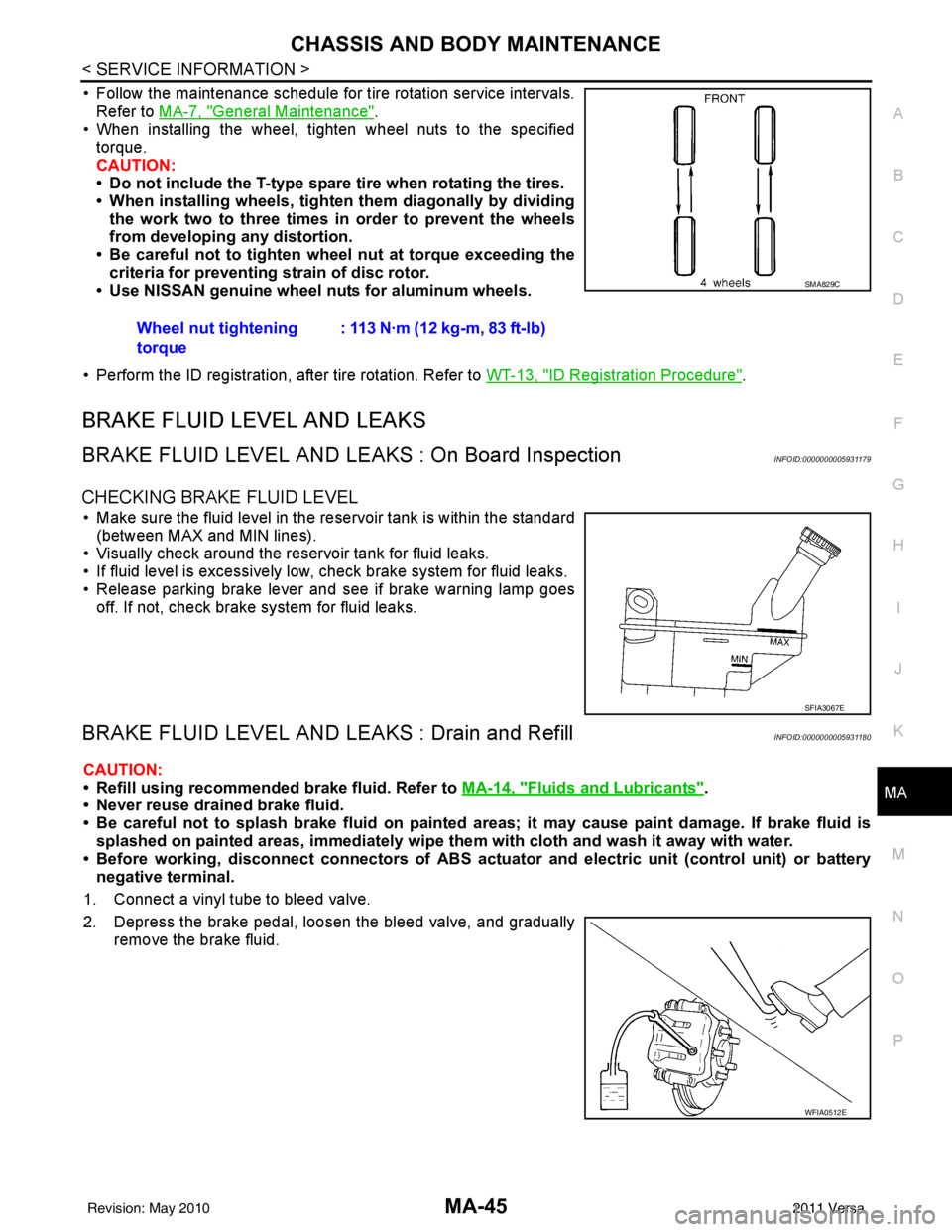
• Follow the maintenance schedule for tire rotation service intervals. Refer to MA-7, "
General Maintenance".
• When installing the wheel, tighten wheel nuts to the specified
torque.
CAUTION:
• Do not include the T-type spare tire when rotating the tires.
• When installing wheels, tighte n them diagonally by dividing
the work two to three times in order to prevent the wheels
from developing any distortion.
• Be careful not to tighten wh eel nut at torque exceeding the
criteria for preventing strain of disc rotor.
• Use NISSAN genuine wheel nuts for aluminum wheels.
• Perform the ID registration, after tire rotation. Refer to WT-13, "
ID Registration Procedure".
BRAKE FLUID LEVEL AND LEAKS
BRAKE FLUID LEVEL AND LEAKS : On Board InspectionINFOID:0000000005931179
CHECKING BRAKE FLUID LEVEL
• Make sure the fluid level in the reservoir tank is within the standard
(between MAX and MIN lines).
• Visually check around the reservoir tank for fluid leaks.
• If fluid level is excessively low, check brake system for fluid leaks.
• Release parking brake lever and see if brake warning lamp goes off. If not, check brake system for fluid leaks.
BRAKE FLUID LEVEL AND LEAKS : Drain and RefillINFOID:0000000005931180
CAUTION:
• Refill using recommended brake fluid. Refer to MA-14, "
Fluids and Lubricants".
• Never reuse drained brake fluid.
• Be careful not to splash brake fluid on painted areas; it may cause paint damage. If brake fluid is
splashed on painted areas, immediately wipe th em with cloth and wash it away with water.
• Before working, disconnect connect ors of ABS actuator and electric unit (control unit) or battery
negative terminal.
1. Connect a vinyl tube to bleed valve.
2. Depress the brake pedal, loosen the bleed valve, and gradually remove the brake fluid.Wheel nut tightening
torque
: 113 N·m (12 kg-m, 83 ft-lb)
SMA829C
SFIA3067E
WFIA0512E
Revision: May 2010
2011 Versa
Page 3217 of 3787
MA-46
< SERVICE INFORMATION >
CHASSIS AND BODY MAINTENANCE
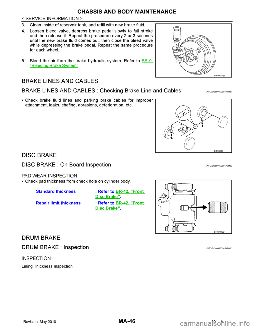
3. Clean inside of reservoir tank, and refill with new brake fluid.
4. Loosen bleed valve, depress brake pedal slowly to full strokeand then release it. Repeat the procedure every 2 or 3 seconds
until the new brake fluid comes out, then close the bleed valve
while depressing the brake pedal. Repeat the same procedure
for each wheel.
5. Bleed the air from the brake hydraulic system. Refer to BR-9,
"Bleeding Brake System" .
BRAKE LINES AND CABLES
BRAKE LINES AND CABLES : Ch ecking Brake Line and CablesINFOID:0000000005931181
• Check brake fluid lines and parking brake cables for improper
attachment, leaks, chafing, abrasions, deterioration, etc.
DISC BRAKE
DISC BRAKE : On Board InspectionINFOID:0000000005931182
PAD WEAR INSPECTION
• Check pad thickness from check hole on cylinder body.
DRUM BRAKE
DRUM BRAKE : InspectionINFOID:0000000005931183
INSPECTION
Lining Thickness Inspection
WFIA0513E
SBR389C
Standard thickness : Refer to BR-42, "Front
Disc Brake".
Repair limit thickness : Refer to BR-42, "
Front
Disc Brake".
BRA0010D
Revision: May 2010 2011 Versa
Page 3218 of 3787
CHASSIS AND BODY MAINTENANCEMA-47
< SERVICE INFORMATION >
C
DE
F
G H
I
J
K
M A
B
MA
N
O P
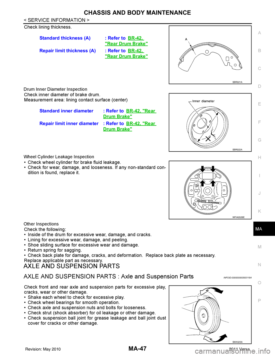
Check lining thickness.
Drum Inner Diameter Inspection
Check inner diameter of brake drum.
Measurement area: lining contact surface (center)
Wheel Cylinder Leakage Inspection
• Check wheel cylinder for brake fluid leakage.
• Check for wear, damage, and looseness. If any non-standard con- dition is found, replace it.
Other Inspections
Check the following:
• Inside of the drum for excessive wear, damage, and cracks.
• Lining for excessive wear, damage, and peeling.
• Shoe sliding surface for excessive wear and damage.
• Return spring for sagging.
• Check back plate for damage, cracks, and deformation. Replace back plate as necessary.
Replace applicable part as necessary.
AXLE AND SUSPENSION PARTS
AXLE AND SUSPENSION PARTS : Axle and Suspension PartsINFOID:0000000005931184
Check front and rear axle and suspension parts for excessive play,
cracks, wear or other damage.
• Shake each wheel to check for excessive play.
• Check wheel bearings for smooth operation.
• Check axle and suspension nuts and bolts for looseness.
• Check strut (shock absorber) for oil leakage or other damage.
• Check suspension ball joint for grease leakage and ball joint dust
cover for cracks or other damage. Standard thickness (A) : Refer to
BR-42,
"Rear Drum Brake"
Repair limit thickness (A) : Refer toBR-42,
"Rear Drum Brake"
SBR021A
Standard inner diameter : Refer toBR-42, "Rear
Drum Brake"
Repair limit inner diameter : Refer toBR-42, "Rear
Drum Brake"
SBR022A
WFIA0528E
SMA525A
Revision: May 2010 2011 Versa
Page 3219 of 3787
MA-48
< SERVICE INFORMATION >
CHASSIS AND BODY MAINTENANCE
DRIVE SHAFT
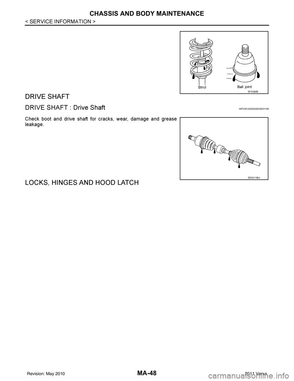
DRIVE SHAFT : Drive ShaftINFOID:0000000005931185
Check boot and drive shaft for cracks, wear, damage and grease
leakage.
LOCKS, HINGES AND HOOD LATCH
SFA392B
SDIA1190J
Revision: May 2010 2011 Versa
Page 3220 of 3787
CHASSIS AND BODY MAINTENANCEMA-49
< SERVICE INFORMATION >
C
DE
F
G H
I
J
K
M A
B
MA
N
O P
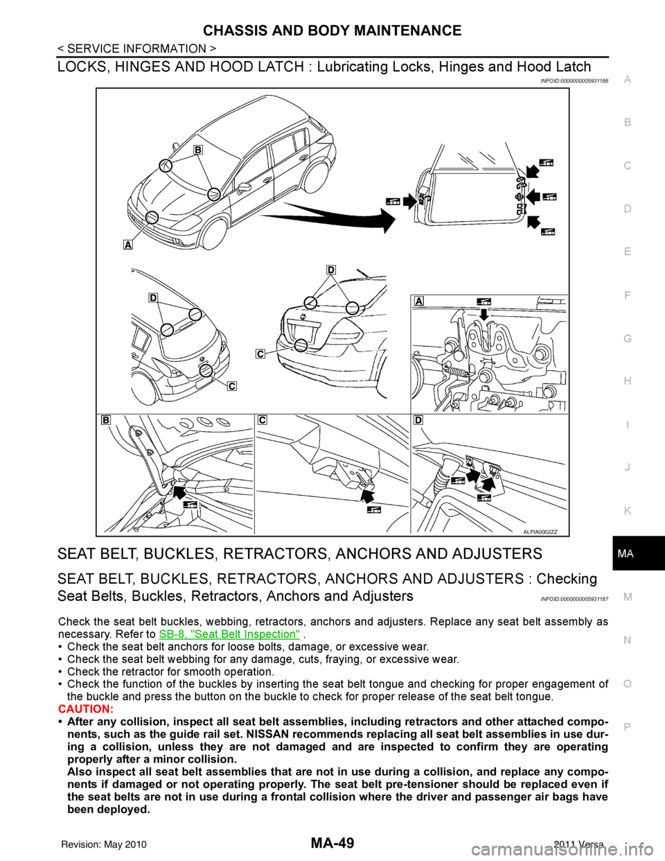
LOCKS, HINGES AND HOOD LATCH : Lubricating Locks, Hinges and Hood Latch
INFOID:0000000005931186
SEAT BELT, BUCKLES, RETRAC TORS, ANCHORS AND ADJUSTERS
SEAT BELT, BUCKLES, RETRACTORS, ANCHORS AND ADJUSTERS : Checking
Seat Belts, Buckles, Retrac tors, Anchors and Adjusters
INFOID:0000000005931187
Check the seat belt buckles, webbing, retractors, anc hors and adjusters. Replace any seat belt assembly as
necessary. Refer to SB-8, "
Seat Belt Inspection" .
• Check the seat belt anchors for loose bolts, damage, or excessive wear.
• Check the seat belt webbing for any damage, cuts, fraying, or excessive wear.
• Check the retractor for smooth operation.
• Check the function of the buckles by inserting the seat belt tongue and checking for proper engagement of
the buckle and press the button on the buckle to c heck for proper release of the seat belt tongue.
CAUTION:
• After any collision, inspect al l seat belt assemblies, including retractors and other attached compo-
nents, such as the guide rail set. NISSAN recomme nds replacing all seat belt assemblies in use dur-
ing a collision, unless they are not damaged an d are inspected to confirm they are operating
properly after a minor collision.
Also inspect all seat belt assemblies that are not in use during a collision, and replace any compo-
nents if damaged or not operating properly. The seat belt pre-tensioner should be replaced even if
the seat belts are not in use during a frontal collision where the driver and passenger air bags have
been deployed.
ALPIA0002ZZ
Revision: May 2010 2011 Versa