NISSAN NAVARA 2005 Repair Workshop Manual
Manufacturer: NISSAN, Model Year: 2005, Model line: NAVARA, Model: NISSAN NAVARA 2005Pages: 3171, PDF Size: 49.59 MB
Page 1301 of 3171
HEAT UP SWITCH
EC-321
C
D
E
F
G
H
I
J
K
L
MA
EC
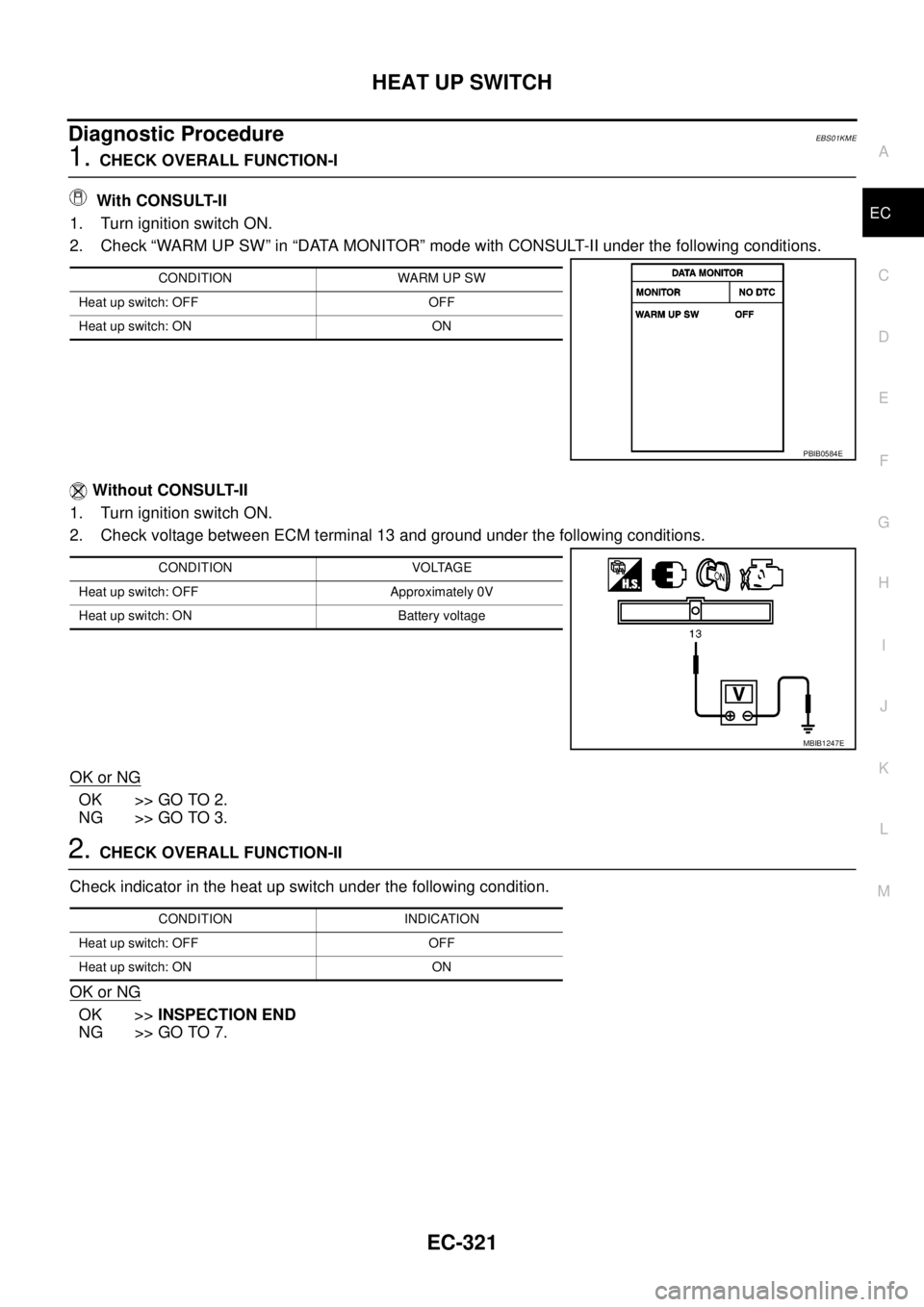
Diagnostic ProcedureEBS01KME
1.CHECK OVERALL FUNCTION-I
With CONSULT-II
1. Turn ignition switch ON.
2. Check “WARM UP SW” in “DATA MONITOR” mode with CONSULT-II under the following conditions.
Without CONSULT-II
1. Turn ignition switch ON.
2. Check voltage between ECM terminal 13 and ground under the following conditions.
OK or NG
OK >> GO TO 2.
NG >> GO TO 3.
2.CHECK OVERALL FUNCTION-II
Check indicator in the heat up switch under the following condition.
OK or NG
OK >>INSPECTION END
NG >> GO TO 7.
CONDITION WARM UP SW
Heat up switch: OFF OFF
Heat up switch: ON ON
PBIB0584E
CONDITION VOLTAGE
Heat up switch: OFF Approximately 0V
Heat up switch: ON Battery voltage
MBIB1247E
CONDITION INDICATION
Heat up switch: OFF OFF
Heat up switch: ON ON
Page 1302 of 3171
EC-322
HEAT UP SWITCH
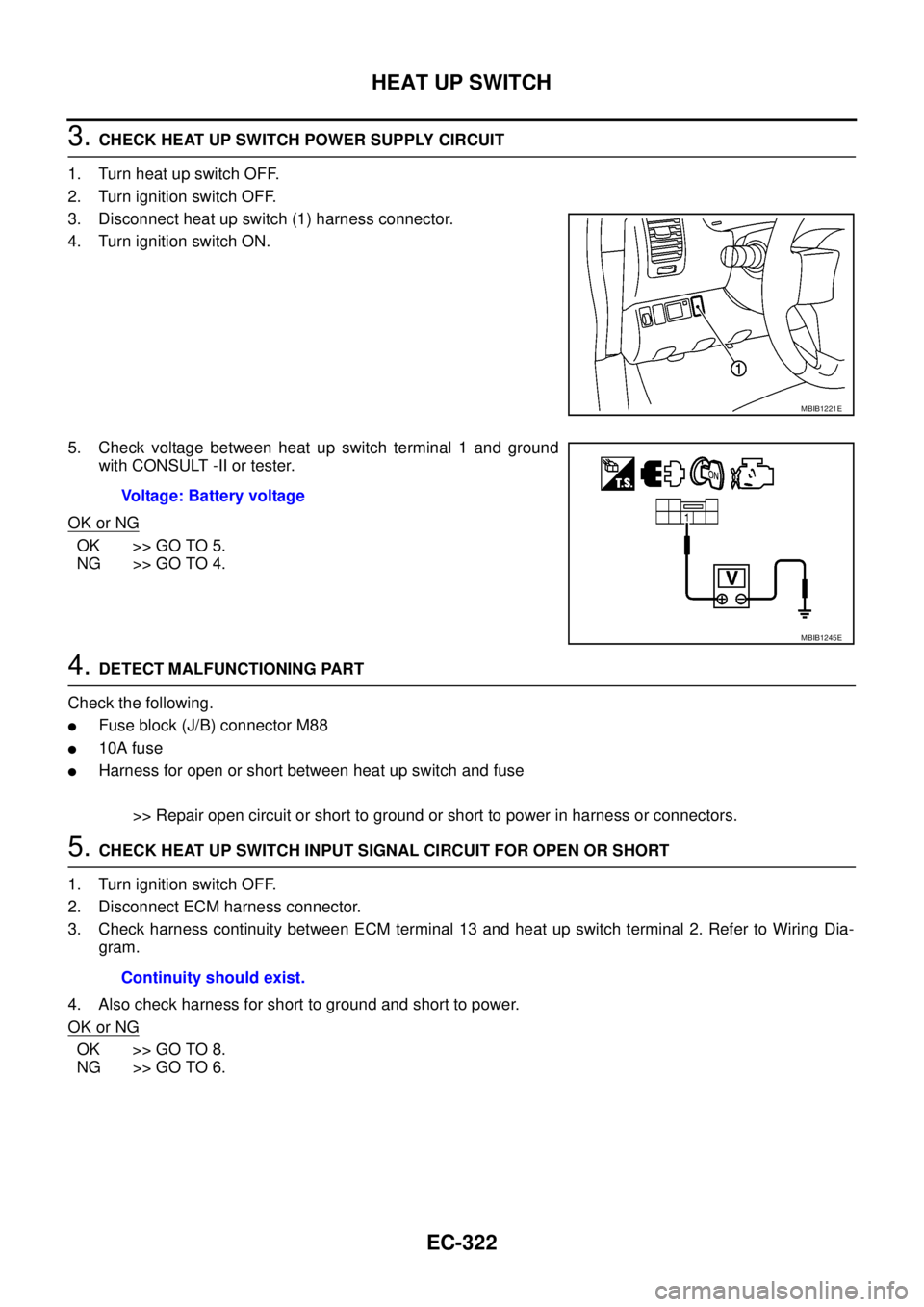
3.CHECK HEAT UP SWITCH POWER SUPPLY CIRCUIT
1. Turn heat up switch OFF.
2. Turn ignition switch OFF.
3. Disconnect heat up switch (1) harness connector.
4. Turn ignition switch ON.
5. Check voltage between heat up switch terminal 1 and ground
with CONSULT -II or tester.
OK or NG
OK >> GO TO 5.
NG >> GO TO 4.
4.DETECT MALFUNCTIONING PART
Check the following.
lFuse block (J/B) connector M88
l10A fuse
lHarness for open or short between heat up switch and fuse
>> Repair open circuit or short to ground or short to power in harness or connectors.
5.CHECK HEAT UP SWITCH INPUT SIGNAL CIRCUIT FOR OPEN OR SHORT
1. Turn ignition switch OFF.
2. Disconnect ECM harness connector.
3. Check harness continuity between ECM terminal 13 and heat up switch terminal 2. Refer to Wiring Dia-
gram.
4. Also check harness for short to ground and short to power.
OK or NG
OK >> GO TO 8.
NG >> GO TO 6.
MBIB1221E
Voltage: Battery voltage
MBIB1245E
Continuity should exist.
Page 1303 of 3171
HEAT UP SWITCH
EC-323
C
D
E
F
G
H
I
J
K
L
MA
EC
6.DETECT MALFUNCTIONING PART
Check the following.
lHarness connectors M91, E101
lHarness connectors E11, F3
lHarness for open or short between ECM and heat up switch
>> Repair open circuit or short to ground or short to power in harness or connectors.
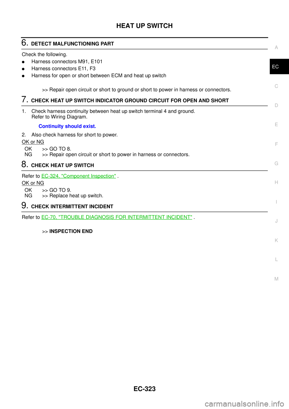
7.CHECK HEAT UP SWITCH INDICATOR GROUND CIRCUIT FOR OPEN AND SHORT
1. Check harness continuity between heat up switch terminal 4 and ground.
Refer to Wiring Diagram.
2. Also check harness for short to power.
OK or NG
OK >> GO TO 8.
NG >> Repair open circuit or short to power in harness or connectors.
8.CHECK HEAT UP SWITCH
Refer toEC-324, "
Component Inspection".
OK or NG
OK >> GO TO 9.
NG >> Replace heat up switch.
9.CHECK INTERMITTENT INCIDENT
Refer toEC-70, "
TROUBLE DIAGNOSIS FOR INTERMITTENT INCIDENT".
>>INSPECTION END Continuity should exist.
Page 1304 of 3171
EC-324
HEAT UP SWITCH
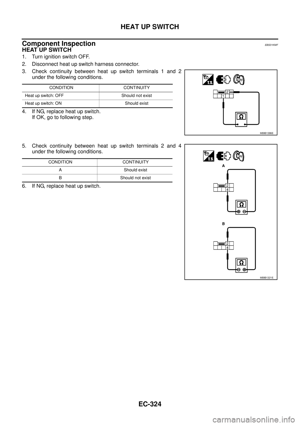
Component Inspection
EBS01KMF
HEAT UP SWITCH
1. Turn ignition switch OFF.
2. Disconnect heat up switch harness connector.
3. Check continuity between heat up switch terminals 1 and 2
under the following conditions.
4. If NG, replace heat up switch.
If OK, go to following step.
5. Check continuity between heat up switch terminals 2 and 4
under the following conditions.
6. If NG, replace heat up switch.
CONDITION CONTINUITY
Heat up switch: OFF Should not exist
Heat up switch: ON Should exist
MBIB1386E
CONDITION CONTINUITY
A Should exist
B Should not exist
MBIB1321E
Page 1305 of 3171
REFRIGERANT PRESSURE SENSOR
EC-325
C
D
E
F
G
H
I
J
K
L
MA
EC
REFRIGERANT PRESSURE SENSORPFP:92136
Component DescriptionEBS01KMG
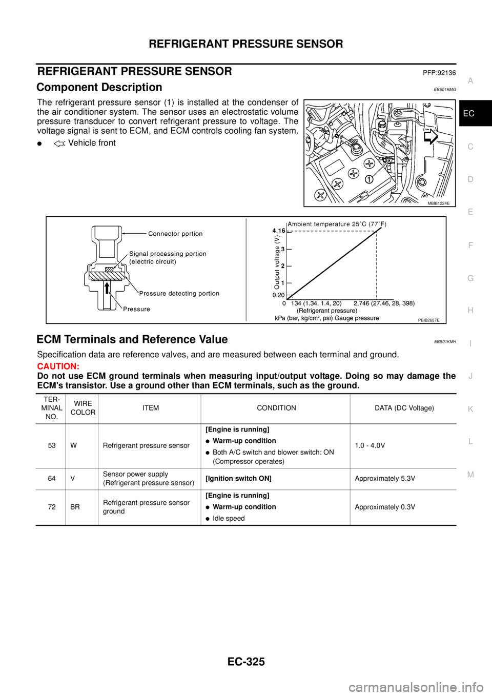
The refrigerant pressure sensor (1) is installed at the condenser of
the air conditioner system. The sensor uses an electrostatic volume
pressure transducer to convert refrigerant pressure to voltage. The
voltage signal is sent to ECM, and ECM controls cooling fan system.
l: Vehicle front
ECM Terminals and Reference ValueEBS01KMH
Specification data are reference valves, and are measured between each terminal and ground.
CAUTION:
Do not use ECM ground terminals when measuring input/output voltage. Doing so may damage the
ECM's transistor. Use a ground other than ECM terminals, such as the ground.
MBIB1224E
PBIB2657E
TER-
MINAL
NO.WIRE
COLORITEM CONDITION DATA (DC Voltage)
53 W Refrigerant pressure sensor[Engine is running]
lWarm-up condition
lBoth A/C switch and blower switch: ON
(Compressor operates)1.0 - 4.0V
64 VSensor power supply
(Refrigerant pressure sensor)[Ignition switch ON]Approximately 5.3V
72 BRRefrigerant pressure sensor
ground[Engine is running]
lWarm-up condition
lIdle speedApproximately 0.3V
Page 1306 of 3171
EC-326
REFRIGERANT PRESSURE SENSOR
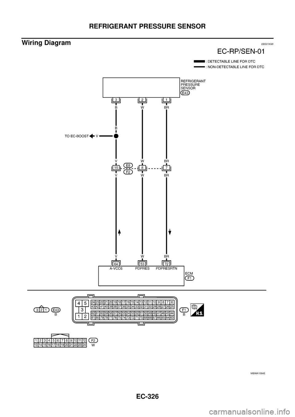
Wiring Diagram
EBS01KMI
MBWA1064E
Page 1307 of 3171
REFRIGERANT PRESSURE SENSOR
EC-327
C
D
E
F
G
H
I
J
K
L
MA
EC
Diagnostic ProcedureEBS01KMJ
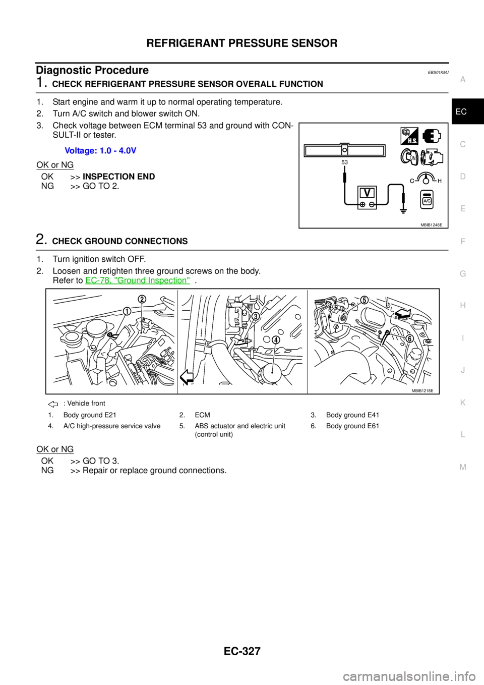
1.CHECK REFRIGERANT PRESSURE SENSOR OVERALL FUNCTION
1. Start engine and warm it up to normal operating temperature.
2. Turn A/C switch and blower switch ON.
3. Check voltage between ECM terminal 53 and ground with CON-
SULT-II or tester.
OK or NG
OK >>INSPECTION END
NG >> GO TO 2.
2.CHECK GROUND CONNECTIONS
1. Turn ignition switch OFF.
2. Loosen and retighten three ground screws on the body.
Refer toEC-78, "
Ground Inspection".
OK or NG
OK >> GO TO 3.
NG >> Repair or replace ground connections.Voltage: 1.0 - 4.0V
MBIB1248E
: Vehicle front
1. Body ground E21 2. ECM 3. Body ground E41
4. A/C high-pressure service valve 5. ABS actuator and electric unit
(control unit)6. Body ground E61
MBIB1218E
Page 1308 of 3171
EC-328
REFRIGERANT PRESSURE SENSOR
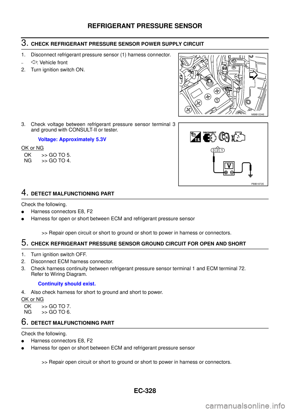
3.CHECK REFRIGERANT PRESSURE SENSOR POWER SUPPLY CIRCUIT
1. Disconnect refrigerant pressure sensor (1) harness connector.
–: Vehicle front
2. Turn ignition switch ON.
3. Check voltage between refrigerant pressure sensor terminal 3
and ground with CONSULT-II or tester.
OK or NG
OK >> GO TO 5.
NG >> GO TO 4.
4.DETECT MALFUNCTIONING PART
Check the following.
lHarness connectors E8, F2
lHarness for open or short between ECM and refrigerant pressure sensor
>> Repair open circuit or short to ground or short to power in harness or connectors.
5.CHECK REFRIGERANT PRESSURE SENSOR GROUND CIRCUIT FOR OPEN AND SHORT
1. Turn ignition switch OFF.
2. Disconnect ECM harness connector.
3. Check harness continuity between refrigerant pressure sensor terminal 1 and ECM terminal 72.
Refer to Wiring Diagram.
4. Also check harness for short to ground and short to power.
OK or NG
OK >> GO TO 7.
NG >> GO TO 6.
6.DETECT MALFUNCTIONING PART
Check the following.
lHarness connectors E8, F2
lHarness for open or short between ECM and refrigerant pressure sensor
>> Repair open circuit or short to ground or short to power in harness or connectors.
MBIB1224E
Voltage: Approximately 5.3V
PBIB1872E
Continuity should exist.
Page 1309 of 3171
REFRIGERANT PRESSURE SENSOR
EC-329
C
D
E
F
G
H
I
J
K
L
MA
EC
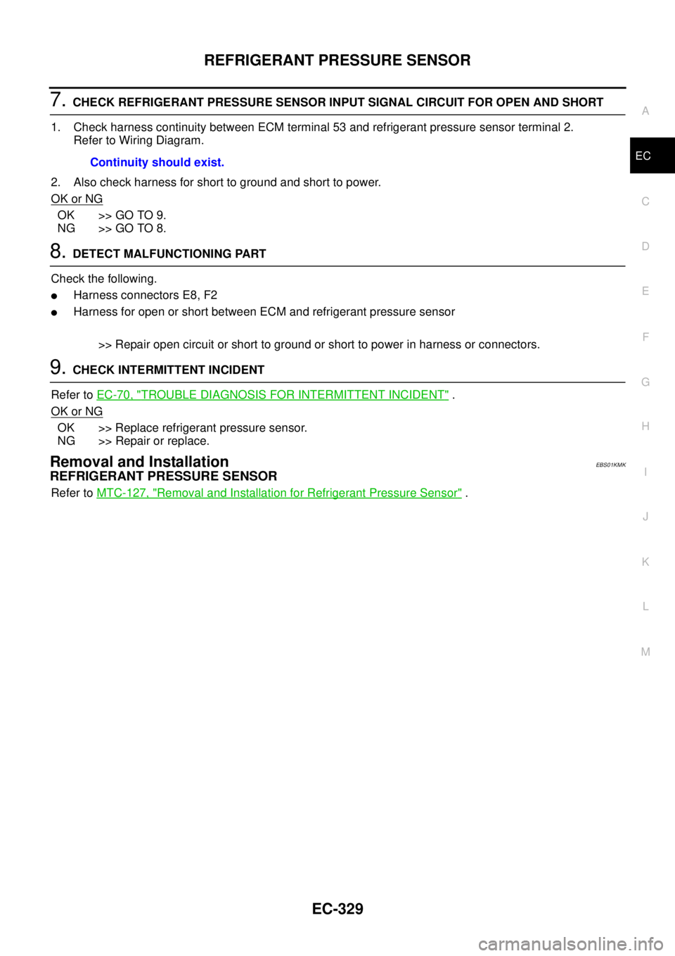
7.CHECK REFRIGERANT PRESSURE SENSOR INPUT SIGNAL CIRCUIT FOR OPEN AND SHORT
1. Check harness continuity between ECM terminal 53 and refrigerant pressure sensor terminal 2.
Refer to Wiring Diagram.
2. Also check harness for short to ground and short to power.
OK or NG
OK >> GO TO 9.
NG >> GO TO 8.
8.DETECT MALFUNCTIONING PART
Check the following.
lHarness connectors E8, F2
lHarness for open or short between ECM and refrigerant pressure sensor
>> Repair open circuit or short to ground or short to power in harness or connectors.
9.CHECK INTERMITTENT INCIDENT
Refer toEC-70, "
TROUBLE DIAGNOSIS FOR INTERMITTENT INCIDENT".
OK or NG
OK >> Replace refrigerant pressure sensor.
NG >> Repair or replace.
Removal and InstallationEBS01KMK
REFRIGERANT PRESSURE SENSOR
Refer toMTC-127, "Removal and Installation for Refrigerant Pressure Sensor". Continuity should exist.
Page 1310 of 3171

EC-330
BRAKE SWITCH
BRAKE SWITCH
PFP:25230
DescriptionEBS01KML
STOP LAMP SWITCH
The stop lamp switch is installed to brake pedal bracket. The switch
senses brake pedal position and sends an ON-OFF signal to the
ECM. The ECM uses the signal to control the fuel injection control
system.
ASCD BRAKE SWITCH (MODELS WITH ASCD)
When depress on the brake pedal, ASCD brake switch is turned OFF and stop lamp switch is turned ON. ECM
detects the state of the brake pedal by this input of two kinds (ON/OFF signal)
Refer toEC-355, "
AUTOMATIC SPEED CONTROL DEVICE (ASCD)"for the ASCD function.
CONSULT-II Reference Value in Data Monitor ModeEBS01KMM
Specification data are reference values.
ECM Terminals and Reference ValueEBS01KMN
Specification data are reference values and are measured between each terminal and ground.
CAUTION:
Do not use ECM ground terminals when measuring input/output voltage. Doing so may result in dam-
age to the ECM's transistor. Use a ground other than ECM terminals, such as the ground.
BBIA0560E
MONITOR ITEM CONDITION SPECIFICATION
BRAKE SW
(Stoplampswitch)
lIgnition switch: ONBrake pedal: Fully released OFF
Brake pedal: Slightly depressed ON
BRAKE SW2
(ASCD brake switch)
lIgnition switch: ON
lBrake pedal: Fully released (A/T)
lClutch pedal and brake pedal:
Fully released (M/T)OFF
lBrake pedal: Slightly depressed (A/T)
lClutch pedal and/or brake pedal:
Slightly depressed (M/T)ON
TERMI-
NAL
NO.WIRE
COLORITEM CONDITIONDATA
(DC Voltage and Pulse Signal)
100 V Stop lamp switch[Ignition switch OFF]
lBrake pedal: Fully releasedApproximately 0V
[Ignition switch OFF]
lBrake pedal: Slightly depressedBATTERY VOLTAGE
(11 - 14V)
101 W ASCD brake switch[Ignition switch ON]
lBrake pedal: Fully released (A/T)
lClutch pedal and brake pedal:
Fully released (M/T)BATTERY VOLTAGE
(11 - 14V)
[Ignition switch ON]
lBrake pedal: Slightly depressed (A/T)
lClutch pedal and/or brake pedal:
Slightly depressed (M/T)Approximately 0V