NISSAN NAVARA 2005 Repair Workshop Manual
Manufacturer: NISSAN, Model Year: 2005, Model line: NAVARA, Model: NISSAN NAVARA 2005Pages: 3171, PDF Size: 49.59 MB
Page 1331 of 3171
ASCD INDICATOR
EC-351
C
D
E
F
G
H
I
J
K
L
MA
EC
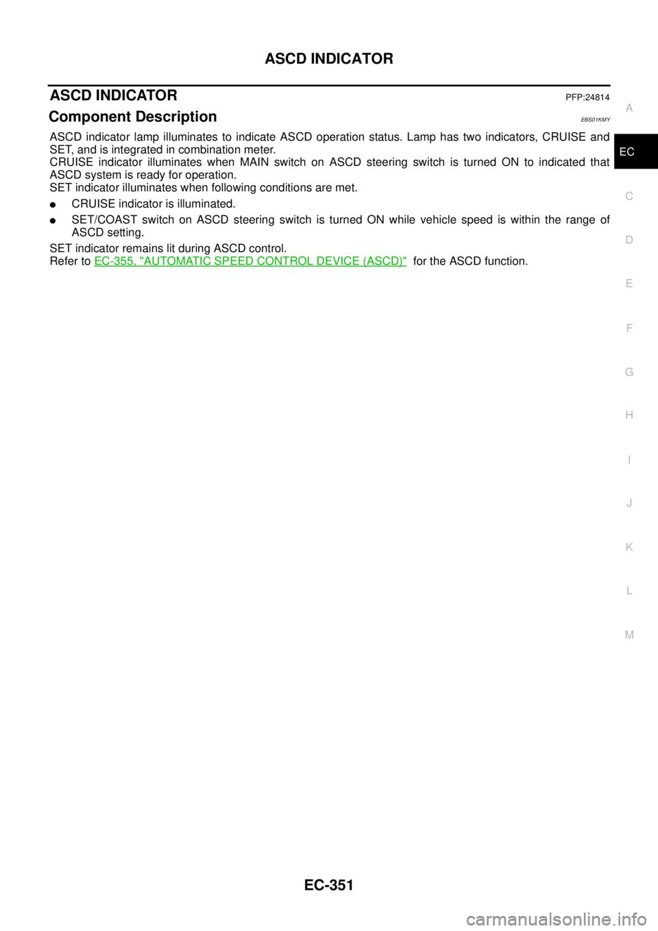
ASCD INDICATORPFP:24814
Component DescriptionEBS01KMY
ASCD indicator lamp illuminates to indicate ASCD operation status. Lamp has two indicators, CRUISE and
SET, and is integrated in combination meter.
CRUISE indicator illuminates when MAIN switch on ASCD steering switch is turned ON to indicated that
ASCD system is ready for operation.
SET indicator illuminates when following conditions are met.
lCRUISE indicator is illuminated.
lSET/COAST switch on ASCD steering switch is turned ON while vehicle speed is within the range of
ASCD setting.
SET indicator remains lit during ASCD control.
Refer toEC-355, "
AUTOMATIC SPEED CONTROL DEVICE (ASCD)"for the ASCD function.
Page 1332 of 3171
EC-352
ASCD INDICATOR
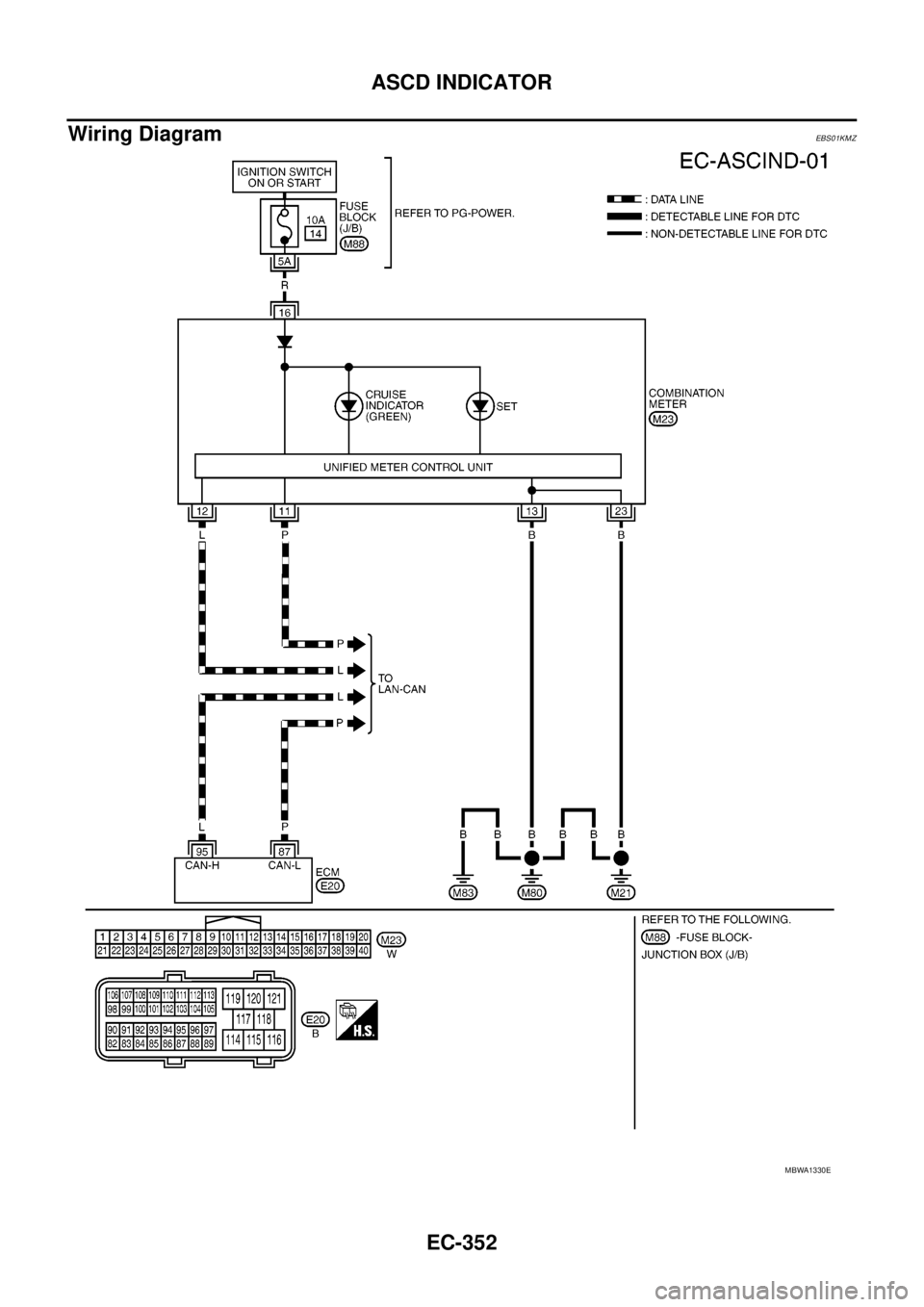
Wiring Diagram
EBS01KMZ
MBWA1330E
Page 1333 of 3171
ASCD INDICATOR
EC-353
C
D
E
F
G
H
I
J
K
L
MA
EC
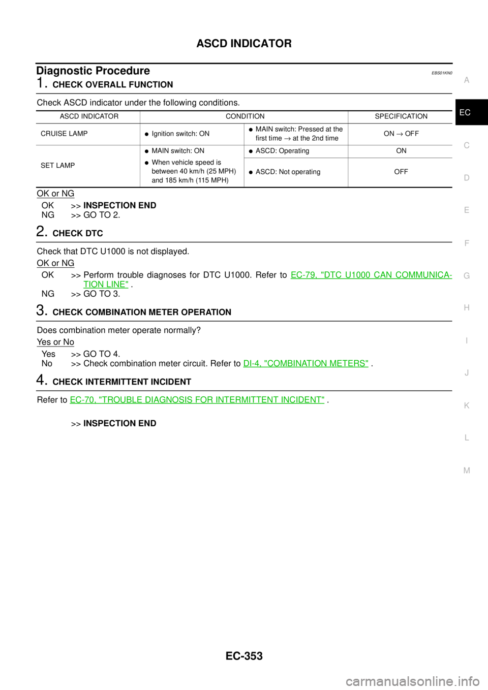
Diagnostic ProcedureEBS01KN0
1.CHECK OVERALL FUNCTION
Check ASCD indicator under the following conditions.
OK or NG
OK >>INSPECTION END
NG >> GO TO 2.
2.CHECK DTC
Check that DTC U1000 is not displayed.
OK or NG
OK >> Perform trouble diagnoses for DTC U1000. Refer toEC-79, "DTC U1000 CAN COMMUNICA-
TION LINE".
NG >> GO TO 3.
3.CHECK COMBINATION METER OPERATION
Does combination meter operate normally?
Ye s o r N o
Ye s > > G O T O 4 .
No >> Check combination meter circuit. Refer toDI-4, "
COMBINATION METERS".
4.CHECK INTERMITTENT INCIDENT
Refer toEC-70, "
TROUBLE DIAGNOSIS FOR INTERMITTENT INCIDENT".
>>INSPECTION END
ASCD INDICATOR CONDITION SPECIFICATION
CRUISE LAMP
lIgnition switch: ONlMAIN switch: Pressed at the
first time®at the 2nd timeON®OFF
SET LAMP
lMAIN switch: ON
lWhen vehicle speed is
between 40 km/h (25 MPH)
and185km/h(115MPH)
lASCD: Operating ON
lASCD: Not operating OFF
Page 1334 of 3171
EC-354
MI & DATA LINK CONNECTORS
MI&DATALINKCONNECTORS
PFP:24814
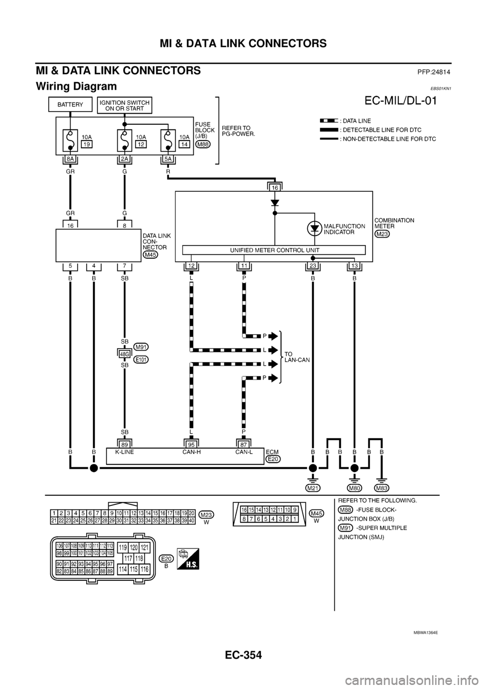
Wiring DiagramEBS01KN1
MBWA1364E
Page 1335 of 3171

AUTOMATIC SPEED CONTROL DEVICE (ASCD)
EC-355
C
D
E
F
G
H
I
J
K
L
MA
EC
AUTOMATIC SPEED CONTROL DEVICE (ASCD)PFP:18930
System DescriptionEBS01KN2
INPUT/OUTPUT SIGNAL CHART
*: This signal is sent to the ECM through CAN communication line.
BASIC ASCD SYSTEM
Refer to Owner's Manual for ASCD operating instructions.
Automatic Speed Control Device (ASCD) allows a driver to keep vehicle at predetermined constant speed
without depressing accelerator pedal. Driver can set vehicle speed in advance between approximately 40 km/
h(25MPH)and185km/h(115MPH).
ECM controls fuel injection value to regulate engine speed.
Operation status of ASCD is indicated by CRUISE indicator and SET indicator in combination meter. If any
malfunction occurs in ASCD system, it automatically deactivates control.
SET OPERATION
Press ASCD MAIN switch. (The CRUISE indicator in combination meter illuminates.)
When vehicle speed reaches a desired speed between approximately 40 km/h (25 MPH) and 185 km/h (115
MPH), press SET/COST switch. (Then SET indicator in combination meter illuminates.)
ACCEL OPERATION
If the RESUME/ACCELERATE switch is depressed during cruise control driving, increase the vehicle speed
until the switch is released or vehicle speed reaches maximum speed controlled by the system.
And then ASCD will keep the new set speed.
CANCEL OPERATION
When any of following conditions exist, cruise operation will be canceled.
lCANCEL switch is depressed
lMore than 2 switches at ASCD steering switch are depressed at the same time (Set speed will be cleared)
lBrake pedal is depressed
lClutch pedal is depressed or gear position is changed to the neutral position (M/T models)
lSelector lever is changed to N, P, R position (A/T models)
lVehicle speed decreased to 13 km/h (8 MPH) lower than the set speed
When the ECM detects any of the following conditions, the ECM will cancel the cruise operation and inform
the driver by blinking indicator lamp.
lMalfunction for some self-diagnoses regarding ASCD control: SET lamp will blink quickly.
If MAIN switch is turned to OFF during ASCD is activated, all of ASCD operations will be canceled and vehicle
speed memory will be erased.
COAST OPERATION
When the SET/COAST switch is depressed during cruise control driving, decrease vehicle set speed until the
switch is released. And then ASCD will keep the new set speed.
RESUME OPERATION
When the RESUME/ACCELERATE switch is depressed after cancel operation other than depressing MAIN
switch is performed, vehicle speed will return to last set speed. To resume vehicle set speed, vehicle condition
must meet following conditions.
Sensor Input signal to ECM ECM function Actuator
ASCD brake switch Brake pedal operation
ASCD vehicle speed control Fuel injector and Fuel pump Stop lamp switch Brake pedal operation
ASCD clutch switch (M/T) Clutch pedal operation
ASCD steering switch ASCD steering switch operation
Park/Neutral position (PNP)
switchGear position
Combination meter* Vehicle speed
TCM* Powertrain revolution
Page 1336 of 3171
EC-356
AUTOMATIC SPEED CONTROL DEVICE (ASCD)
lBrake pedal is released
lClutch pedal is released (M/T models)
lSelector lever is in other than P and N positions (A/T models)
lVehicle speed is greater than 40 km/h (25 MPH) and less than 185 km/h (115 MPH)
Component DescriptionEBS01KN3
ASCD STEERING SWITCH
Refer toEC-206.
ASCD BRAKE SWITCH
Refer toEC-189andEC-330.
ASCD CLUTCH SWITCH
Refer toEC-189andEC-330.
STOP LAMP SWITCH
Refer toEC-189andEC-330.
ASCD INDICATOR
Refer toEC-351.
Page 1337 of 3171
SERVICE DATA AND SPECIFICATIONS (SDS)
EC-357
C
D
E
F
G
H
I
J
K
L
MA
EC
SERVICE DATA AND SPECIFICATIONS (SDS)PFP:00100
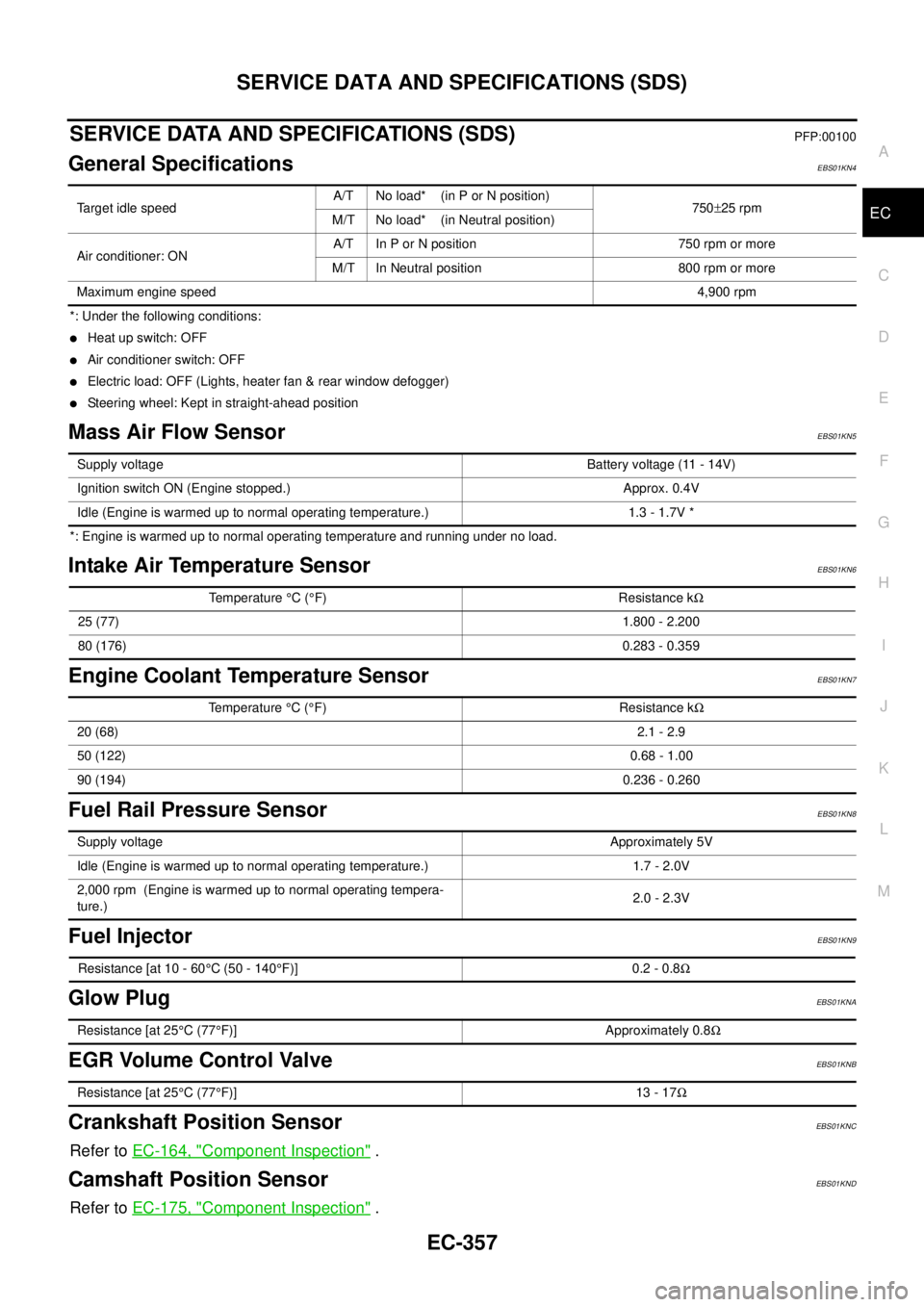
General SpecificationsEBS01KN4
*: Under the following conditions:
lHeat up switch: OFF
lAir conditioner switch: OFF
lElectric load: OFF (Lights, heater fan & rear window defogger)
lSteering wheel: Kept in straight-ahead position
Mass Air Flow SensorEBS01KN5
*: Engine is warmed up to normal operating temperature and running under no load.
Intake Air Temperature SensorEBS01KN6
Engine Coolant Temperature SensorEBS01KN7
Fuel Rail Pressure SensorEBS01KN8
Fuel InjectorEBS01KN9
Glow PlugEBS01KNA
EGR Volume Control ValveEBS01KNB
Crankshaft Position SensorEBS01KNC
Refer toEC-164, "Component Inspection".
Camshaft Position SensorEBS01KND
Refer toEC-175, "Component Inspection".
Target idle speedA/T No load* (in P or N position)
750±25 rpm
M/T No load* (in Neutral position)
Air conditioner: ONA/T In P or N position 750 rpm or more
M/T In Neutral position 800 rpm or more
Maximum engine speed4,900 rpm
Supply voltageBattery voltage (11 - 14V)
Ignition switch ON (Engine stopped.) Approx. 0.4V
Idle (Engine is warmed up to normal operating temperature.) 1.3 - 1.7V *
Temperature°C(°F) Resistance kW
25 (77)1.800 - 2.200
80 (176)0.283 - 0.359
Temperature°C(°F) Resistance kW
20 (68)2.1 - 2.9
50 (122)0.68 - 1.00
90 (194)0.236 - 0.260
Supply voltageApproximately 5V
Idle (Engine is warmed up to normal operating temperature.) 1.7 - 2.0V
2,000 rpm (Engine is warmed up to normal operating tempera-
ture.)2.0 - 2.3V
Resistance [at 10 - 60°C (50 - 140°F)] 0.2 - 0.8W
Resistance [at 25°C(77°F)] Approximately 0.8W
Resistance [at 25°C(77°F)] 13 - 17W
Page 1338 of 3171
![NISSAN NAVARA 2005 Repair Workshop Manual EC-358
SERVICE DATA AND SPECIFICATIONS (SDS)
Fuel Pump
EBS01KNE
Resistance [at 10 - 60°C (50 - 140°F)] 1.5 - 3.0W NISSAN NAVARA 2005 Repair Workshop Manual EC-358
SERVICE DATA AND SPECIFICATIONS (SDS)
Fuel Pump
EBS01KNE
Resistance [at 10 - 60°C (50 - 140°F)] 1.5 - 3.0W](/img/5/57362/w960_57362-1337.png)
EC-358
SERVICE DATA AND SPECIFICATIONS (SDS)
Fuel Pump
EBS01KNE
Resistance [at 10 - 60°C (50 - 140°F)] 1.5 - 3.0W
Page 1339 of 3171

EI-1
EXTERIOR & INTERIOR
IBODY
CONTENTS
C
D
E
F
G
H
J
K
L
M
SECTIONEI
A
B
EI
EXTERIOR & INTERIOR
PRECAUTIONS .......................................................... 3
Service Notice .......................................................... 3
Precautions for Supplemental Restraint System
(SRS)“AIRBAG”and“SEATBELTPRE-TEN-
SIONER” .................................................................. 3
Precautions for SRS “AIR BAG” and “SEAT BELT
PRE-TENSIONER” Service ..................................... 3
Precautions for Procedures without Cowl Top Cover..... 4
PREPARATION ........................................................... 5
Commercial Service Tools ........................................ 5
SQUEAK AND RATTLE TROUBLE DIAGNOSES..... 6
Work Flow ................................................................ 6
CUSTOMER INTERVIEW ..................................... 6
DUPLICATE THE NOISE AND TEST DRIVE ....... 7
CHECK RELATED SERVICE BULLETINS ........... 7
LOCATE THE NOISE AND IDENTIFY THE
ROOT CAUSE ...................................................... 7
REPAIR THE CAUSE ........................................... 7
CONFIRM THE REPAIR ....................................... 7
Generic Squeak and Rattle Troubleshooting ........... 7
INSTRUMENT PANEL .......................................... 7
CENTER CONSOLE ............................................. 8
DOORS ................................................................. 8
TRUNK .................................................................. 8
SUNROOF/HEADLINING ..................................... 8
OVERHEAD CONSOLE (FRONT AND REAR)..... 8
SEATS ................................................................... 9
UNDERHOOD ....................................................... 9
Diagnostic Worksheet ............................................ 10
CLIP AND FASTENER ............................................. 12
Clip and Fastener ................................................... 12
FRONT BUMPER ..................................................... 15
Removal and Installation ........................................ 15
FRONT BUMPER ............................................... 15
REAR BUMPER ....................................................... 17
Removal and Installation ........................................ 17
REMOVAL ........................................................... 17
INSTALLATION ................................................... 18FRONT GRILLE ........................................................ 19
Removal and Installation ........................................ 19
REMOVAL ........................................................... 19
INSTALLATION ................................................... 19
COWL TOP ............................................................... 20
Removal and Installation ........................................ 20
REMOVAL ........................................................... 20
INSTALLATION ................................................... 20
FENDER PROTECTOR ............................................ 21
Components ........................................................... 21
Removal and Installation of Front Fender Protector... 22
REMOVAL ........................................................... 22
INSTALLATION ................................................... 22
Removal and Installation of Rear Fender Protector... 22
REMOVAL ........................................................... 22
INSTALLATION ................................................... 22
MUDGUARD ............................................................. 23
Removal and Installation ........................................ 23
RUNNING BOARDS ................................................. 24
Removal and Installation ........................................ 24
REMOVAL ........................................................... 25
INSTALLATION ................................................... 25
ROOF RACK ............................................................. 26
Removal and Installation ........................................ 26
REMOVAL ........................................................... 26
INSTALLATION ................................................... 26
DOOR OUTSIDE MOLDING ..................................... 27
Removal and Installation ........................................ 27
FRONT DOOR OUTSIDE MOLDING .................. 27
SIDE GUARD MOLDING .......................................... 28
Removal and Installation ........................................ 28
REMOVAL ........................................................... 29
INSTALLATION ................................................... 29
DOOR FINISHER ...................................................... 30
Removal and Installation ........................................ 30
FRONT DOOR .................................................... 30
REAR DOOR - DOUBLE CAB ............................ 31
REAR DOOR - KING CAB .................................. 32
BODY SIDE TRIM ..................................................... 33
Components ........................................................... 33
Page 1340 of 3171

EI-2
DOUBLE CAB ..................................................... 33
KING CAB ........................................................... 34
Removal and installation ......................................... 34
LOWER DASH SIDE FINISHER ......................... 34
CENTER PILLAR LOWER FINISHER ................ 35
CENTER PILLAR UPPER FINISHER ................. 35
FRONT PILLAR UPPER FINISHER .................... 35
FRONT PILLAR LOWER FINISHER ................... 35
KICK PLATES ...................................................... 35
REAR ................................................................... 36
FLOOR TRIM ............................................................ 38
Removal and Installation ........................................ 38
REMOVAL ........................................................... 39
INSTALLATION .................................................... 39HEADLINING ............................................................. 40
Removal and Installation ......................................... 40
REMOVAL ............................................................ 41
INSTALLATION .................................................... 41
BED RAILS AND TRIM ............................................. 42
Removal and Installation ......................................... 42
REMOVAL ............................................................ 43
INSTALLATION .................................................... 43
TAIL GATE FINISHER ............................................... 44
Removal and Installation ......................................... 44
REMOVAL ............................................................ 44
INSTALLATION .................................................... 44