NISSAN NAVARA 2005 Repair Workshop Manual
NAVARA 2005
NISSAN
NISSAN
https://www.carmanualsonline.info/img/5/57362/w960_57362-0.png
NISSAN NAVARA 2005 Repair Workshop Manual
Trending: wheelbase, brakes troubleshoot, jump cable, flat tire, audio, wiring, coolant level
Page 1361 of 3171
MUDGUARD
EI-23
C
D
E
F
G
H
J
K
L
MA
B
EI
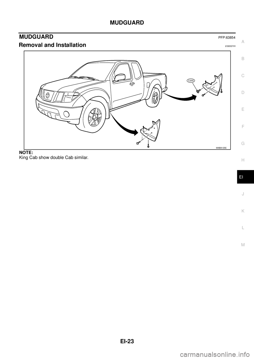
MUDGUARDPFP:63854
Removal and InstallationEIS00DYH
NOTE:
King Cab show double Cab similar.
MIIB9125E
Page 1362 of 3171
EI-24
RUNNING BOARDS
RUNNING BOARDS
PFP:96110
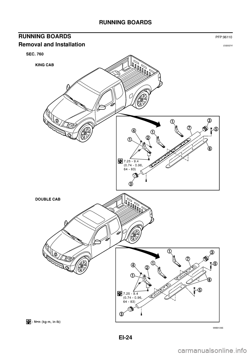
Removal and InstallationEIS00DYI
MIIB9126E
Page 1363 of 3171
RUNNING BOARDS
EI-25
C
D
E
F
G
H
J
K
L
MA
B
EI
REMOVAL
1. Remove screws and clip, fixing mudguard, then remove it (if equipped).
2. Remove bolts and remove running board from running board brackets.
3. Remove screw and remove end cap.
4. Remove screws fixing step pad and remove step pad from running board.
5. Remove nuts and bolts and remove running board brackets.
INSTALLATION
Installation is in the reverse order of removal.
1. Running board bracket 2. Weld stud 3. End cap
4. Nut 5. Screw 6. Step pad
7. Running board
Page 1364 of 3171
EI-26
ROOF RACK
ROOF RACK
PFP:73155
Removal and InstallationEIS00DYJ
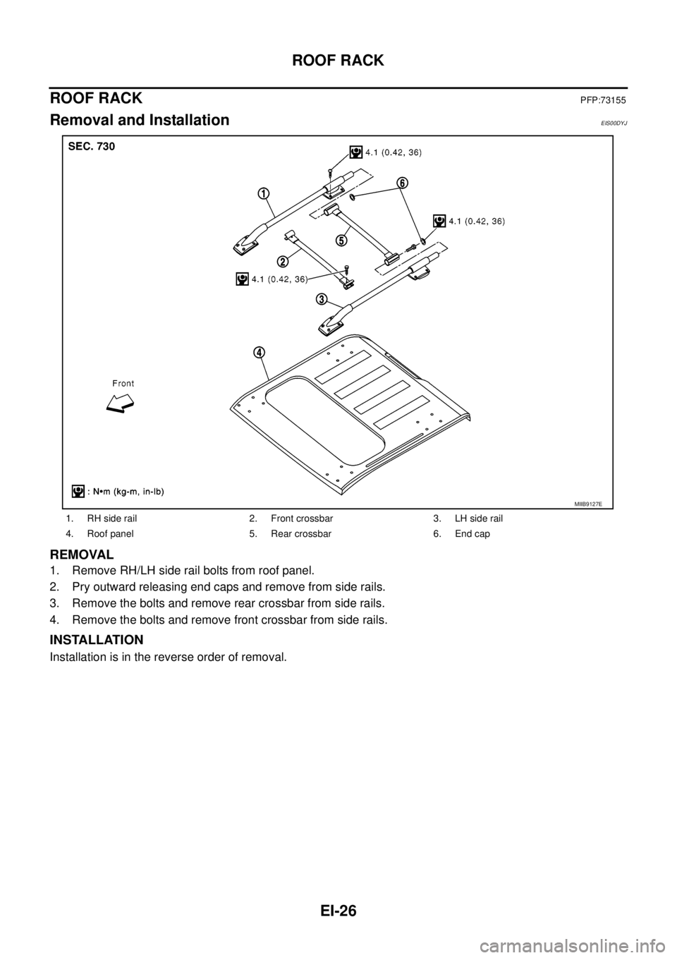
REMOVAL
1. Remove RH/LH side rail bolts from roof panel.
2. Pry outward releasing end caps and remove from side rails.
3. Remove the bolts and remove rear crossbar from side rails.
4. Remove the bolts and remove front crossbar from side rails.
INSTALLATION
Installation is in the reverse order of removal.
1. RH side rail 2. Front crossbar 3. LH side rail
4. Roof panel 5. Rear crossbar 6. End cap
MIIB9127E
Page 1365 of 3171
DOOR OUTSIDE MOLDING
EI-27
C
D
E
F
G
H
J
K
L
MA
B
EI
DOOR OUTSIDE MOLDINGPFP:82820
Removal and InstallationEIS00DYK
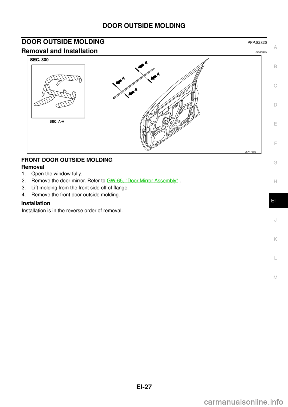
FRONT DOOR OUTSIDE MOLDING
Removal
1. Open the window fully.
2. Remove the door mirror. Refer toGW-65, "
Door Mirror Assembly".
3. Lift molding from the front side off of flange.
4. Remove the front door outside molding.
Installation
Installation is in the reverse order of removal.
LIIA1780E
Page 1366 of 3171
EI-28
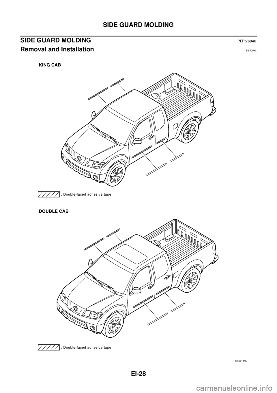
SIDE GUARD MOLDING
SIDE GUARD MOLDING
PFP:76840
Removal and InstallationEIS00DYL
MIIB9144E
Page 1367 of 3171
SIDE GUARD MOLDING
EI-29
C
D
E
F
G
H
J
K
L
MA
B
EI
REMOVAL
CAUTION:
Never apply tack-paper adhesive remover to body panel surface finished with lacquer-based paints.
lOriginal side guard molding is affixed to body panel with double-faced adhesive tape.
1. Heat molding to between 30°and 40°C(86°to 104°F) with a heat gun.
2. Raise end of molding and cut away tape to remove molding. Remove all traces of tape.
INSTALLATION
lOn vehicles coated with Hard Clear Coat, use double-faced 3M adhesive tape Product No. 4210 or equiv-
alent, after priming with 3M primer Product No. N200, C-100 or equivalent.
lThe repair parts are also affixed with double-faced adhesive tape.
lTo re-use existing molding, clean all traces of double sided tape from the molding and apply new double-
facedtapetothemolding.
1. Clean the panel surface with isopropyl alcohol or equivalent to degrease the surface.
2. Heat the panel and molding tape surface to 30°to 40°C(86°to 104°F).
3. Remove the backing sheet from the tape surface.
lAlign the locating pin into the hole in the outer door.
lContinue aligning the pins into their corresponding holes in the outer door during installation.
4. Press ends by hand and use a roller to apply 5 kg-f (11 lbs-f) to press molding to door surface.
lApply even pressure along molding to insure proper wet out.
CAUTION:
To secure contact, do not wash vehicle for 24 hours after installation.
Page 1368 of 3171
EI-30
DOOR FINISHER
DOOR FINISHER
PFP:80900
Removal and InstallationEIS00DYM
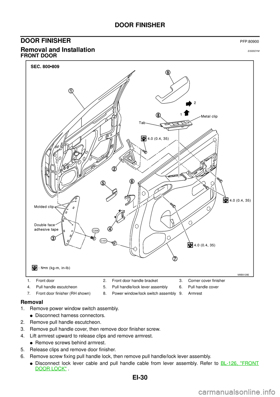
FRONT DOOR
Removal
1. Remove power window switch assembly.
lDisconnect harness connectors.
2. Remove pull handle escutcheon.
3. Remove pull handle cover, then remove door finisher screw.
4. Lift armrest upward to release clips and remove armrest.
lRemove screws behind armrest.
5. Release clips and remove door finisher.
6. Remove screw fixing pull handle lock, then remove pull handle/lock lever assembly.
lDisconnect lock lever cable and pull handle cable from lever assembly. Refer toBL-126, "FRONT
DOOR LOCK".
1. Front door 2. Front door handle bracket 3. Corner cover finisher
4. Pull handle escutcheon 5. Pull handle/lock lever assembly 6. Pull handle cover
7. Front door finisher (RH shown) 8. Power window/lock switch assembly 9. Armrest
MIIB9128E
Page 1369 of 3171
DOOR FINISHER
EI-31
C
D
E
F
G
H
J
K
L
MA
B
EI
Installation
Installation is in the reverse order of removal.
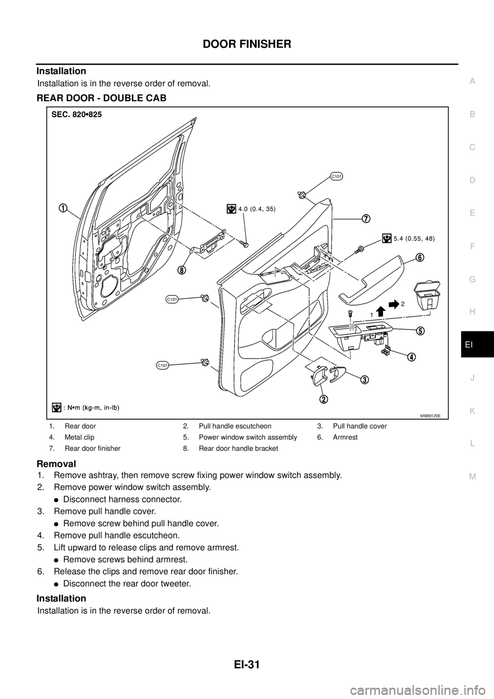
REAR DOOR - DOUBLE CAB
Removal
1. Remove ashtray, then remove screw fixing power window switch assembly.
2. Remove power window switch assembly.
lDisconnect harness connector.
3. Remove pull handle cover.
lRemove screw behind pull handle cover.
4. Remove pull handle escutcheon.
5. Lift upward to release clips and remove armrest.
lRemove screws behind armrest.
6. Release the clips and remove rear door finisher.
lDisconnect the rear door tweeter.
Installation
Installation is in the reverse order of removal.
1. Rear door 2. Pull handle escutcheon 3. Pull handle cover
4. Metal clip 5. Power window switch assembly 6. Armrest
7. Rear door finisher 8. Rear door handle bracket
MIIB9129E
Page 1370 of 3171
EI-32
DOOR FINISHER
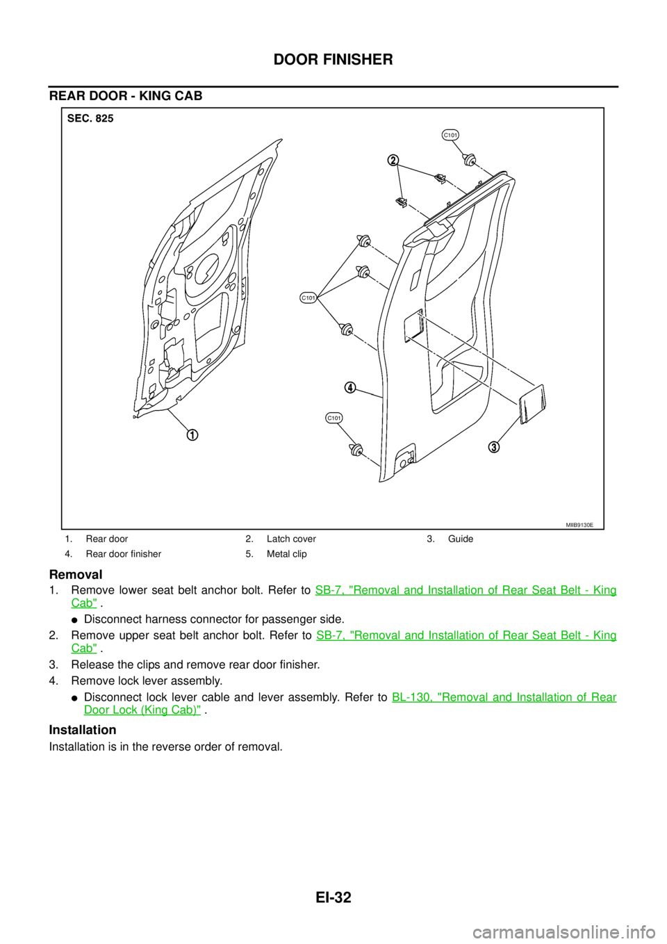
REAR DOOR - KING CAB
Removal
1. Remove lower seat belt anchor bolt. Refer toSB-7, "Removal and Installation of Rear Seat Belt - King
Cab".
lDisconnect harness connector for passenger side.
2. Remove upper seat belt anchor bolt. Refer toSB-7, "
Removal and Installation of Rear Seat Belt - King
Cab".
3. Release the clips and remove rear door finisher.
4. Remove lock lever assembly.
lDisconnect lock lever cable and lever assembly. Refer toBL-130, "Removal and Installation of Rear
Door Lock (King Cab)".
Installation
Installation is in the reverse order of removal.
1. Rear door 2. Latch cover 3. Guide
4. Rear door finisher 5. Metal clip
MIIB9130E
Trending: width, fold seats, keyless entry, timing belt, wiper fluid, steering wheel, clock setting
