NISSAN NAVARA 2005 Repair Workshop Manual
Manufacturer: NISSAN, Model Year: 2005, Model line: NAVARA, Model: NISSAN NAVARA 2005Pages: 3171, PDF Size: 49.59 MB
Page 1481 of 3171
CYLINDER HEAD
EM-99
C
D
E
F
G
H
I
J
K
L
MA
EM
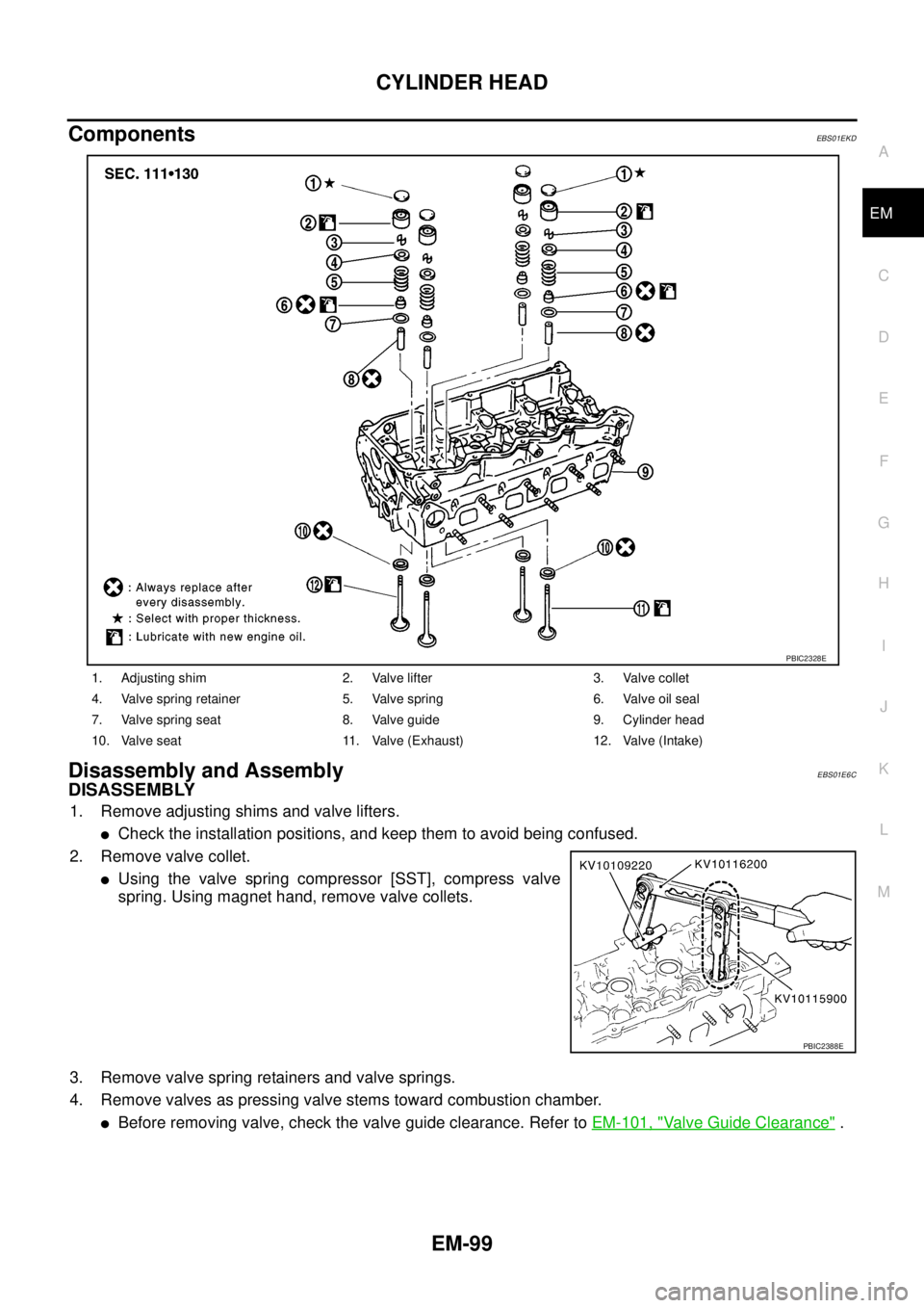
ComponentsEBS01EKD
Disassembly and AssemblyEBS01E6C
DISASSEMBLY
1. Remove adjusting shims and valve lifters.
lCheck the installation positions, and keep them to avoid being confused.
2. Remove valve collet.
lUsing the valve spring compressor [SST], compress valve
spring. Using magnet hand, remove valve collets.
3. Remove valve spring retainers and valve springs.
4. Remove valves as pressing valve stems toward combustion chamber.
lBefore removing valve, check the valve guide clearance. Refer toEM-101, "Valve Guide Clearance".
1. Adjusting shim 2. Valve lifter 3. Valve collet
4. Valve spring retainer 5. Valve spring 6. Valve oil seal
7. Valve spring seat 8. Valve guide 9. Cylinder head
10. Valve seat 11. Valve (Exhaust) 12. Valve (Intake)
PBIC2328E
PBIC2388E
Page 1482 of 3171
EM-100
CYLINDER HEAD
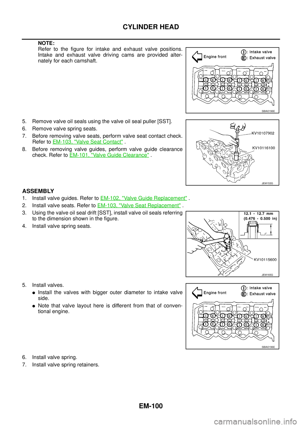
NOTE:
Refer to the figure for intake and exhaust valve positions.
Intake and exhaust valve driving cams are provided alter-
nately for each camshaft.
5. Remove valve oil seals using the valve oil seal puller [SST].
6. Remove valve spring seats.
7. Before removing valve seats, perform valve seat contact check.
Refer toEM-103, "
Va l v e S e a t C o n t a c t".
8. Before removing valve guides, perform valve guide clearance
check. Refer toEM-101, "
Valve Guide Clearance".
ASSEMBLY
1. Install valve guides. Refer toEM-102, "Valve Guide Replacement".
2. Install valve seats. Refer toEM-103, "
Valve Seat Replacement".
3. Using the valve oil seal drift [SST], install valve oil seals referring
to the dimension shown in the figure.
4. Install valve spring seats.
5. Install valves.
lInstall the valves with bigger outer diameter to intake valve
side.
lNote that valve layout here is different from that of conven-
tional engine.
6. Install valve spring.
7. Install valve spring retainers.
SBIA0196E
JEM153G
JEM165G
SBIA0196E
Page 1483 of 3171
![NISSAN NAVARA 2005 Repair Workshop Manual CYLINDER HEAD
EM-101
C
D
E
F
G
H
I
J
K
L
MA
EM
8. Using the valve spring compressor [SST], compress valve
springs.
Then install valve collets using magnet hand.
lAfter installing valve collets, tap th NISSAN NAVARA 2005 Repair Workshop Manual CYLINDER HEAD
EM-101
C
D
E
F
G
H
I
J
K
L
MA
EM
8. Using the valve spring compressor [SST], compress valve
springs.
Then install valve collets using magnet hand.
lAfter installing valve collets, tap th](/img/5/57362/w960_57362-1482.png)
CYLINDER HEAD
EM-101
C
D
E
F
G
H
I
J
K
L
MA
EM
8. Using the valve spring compressor [SST], compress valve
springs.
Then install valve collets using magnet hand.
lAfter installing valve collets, tap the stem end using the plastic
hammer, and check the installation status.
9. Install valve lifters and adjusting shims to the same positions as before.
INSPECTION AFTER DISASSEMBLY
Valve Dimension
lCheck dimensions of each valve. For dimensions, refer toEM-
136, "Valve Dimensions".
lIf dimensions are out of the standard, replace valve.
Valve Guide Clearance
Valve Stem Diameter
lMeasure diameter of valve stem with micrometer.
Valve Guide Inner Diameter
lMeasure inner diameter of valve guide with inside micrometer.
Valve Guide Clearance
l(Valve guide clearance) = (Valve guide inner diameter) – (Valve stem diameter).
PBIC2388E
SEM188A
Standard
Intake : 5.965 - 5.980 mm (0.2348 - 0.2354 in)
Exhaust : 5.945 - 5.960 mm (0.2341 - 0.2346 in)
SEM938C
Standard
Intake and Exhaust : 6.000 - 6.018 mm (0.2362 - 0.2369 in)
Valve guide clearance:
Standard
Intake : 0.020 - 0.053 mm (0.0008 - 0.0021 in)
Exhaust : 0.040 - 0.073 mm (0.0016 - 0.0029 in)
Limit
Intake : 0.08 mm (0.0031 in)
Exhaust : 0.10 mm (0.0039 in)
Page 1484 of 3171
![NISSAN NAVARA 2005 Repair Workshop Manual EM-102
CYLINDER HEAD
lIf it exceeds the limit, replace valve and/or valve guide.
Valve Guide Replacement
When removing valve guide, replace it with oversized [0.2 mm (0.0008 in)] valve guide.
1. Heat NISSAN NAVARA 2005 Repair Workshop Manual EM-102
CYLINDER HEAD
lIf it exceeds the limit, replace valve and/or valve guide.
Valve Guide Replacement
When removing valve guide, replace it with oversized [0.2 mm (0.0008 in)] valve guide.
1. Heat](/img/5/57362/w960_57362-1483.png)
EM-102
CYLINDER HEAD
lIf it exceeds the limit, replace valve and/or valve guide.
Valve Guide Replacement
When removing valve guide, replace it with oversized [0.2 mm (0.0008 in)] valve guide.
1. Heat cylinder head to 110 to 130°C(230to266°F) in oil bath.
2. Using the valve guide drift (commercial service tool), tap valve
guides out from the combustion chamber side.
WARNING:
Cylinder head contains heat, when working, wear protective
equipment to avoid getting burned.
3. Ream cylinder head valve guide hole with the valve guide
reamer (commercial service tool).
4. Heat cylinder head to 110 to 130°C(230to266°F) in oil bath.
SEM008A
SEM931C
Valve guide hole diameter (for service parts):
10.175 - 10.196 mm (0.4006 - 0.4014 in)
SEM932C
SEM008A
Page 1485 of 3171
CYLINDER HEAD
EM-103
C
D
E
F
G
H
I
J
K
L
MA
EM
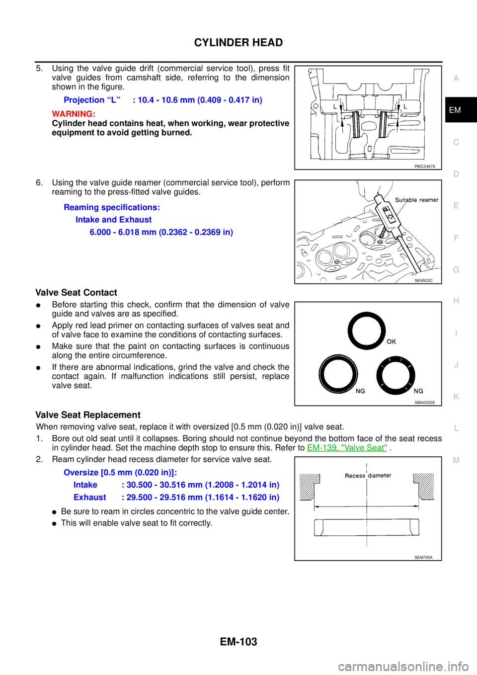
5. Using the valve guide drift (commercial service tool), press fit
valve guides from camshaft side, referring to the dimension
showninthefigure.
WARNING:
Cylinder head contains heat, when working, wear protective
equipment to avoid getting burned.
6. Using the valve guide reamer (commercial service tool), perform
reaming to the press-fitted valve guides.
Valve Seat Contact
lBefore starting this check, confirm that the dimension of valve
guide and valves are as specified.
lApply red lead primer on contacting surfaces of valves seat and
of valve face to examine the conditions of contacting surfaces.
lMake sure that the paint on contacting surfaces is continuous
along the entire circumference.
lIf there are abnormal indications, grind the valve and check the
contact again. If malfunction indications still persist, replace
valve seat.
Valve Seat Replacement
When removing valve seat, replace it with oversized [0.5 mm (0.020 in)] valve seat.
1. Bore out old seat until it collapses. Boring should not continue beyond the bottom face of the seat recess
in cylinder head. Set the machine depth stop to ensure this. Refer toEM-139, "
Valve Seat".
2. Ream cylinder head recess diameter for service valve seat.
lBe sure to ream in circles concentric to the valve guide center.
lThis will enable valve seat to fit correctly.Projection “L” : 10.4 - 10.6 mm (0.409 - 0.417 in)
PBIC2497E
Reaming specifications:
Intake and Exhaust
6.000 - 6.018 mm (0.2362 - 0.2369 in)
SEM932C
SBIA0322E
Oversize [0.5 mm (0.020 in)]:
Intake : 30.500 - 30.516 mm (1.2008 - 1.2014 in)
Exhaust : 29.500 - 29.516 mm (1.1614 - 1.1620 in)
SEM795A
Page 1486 of 3171
EM-104
CYLINDER HEAD
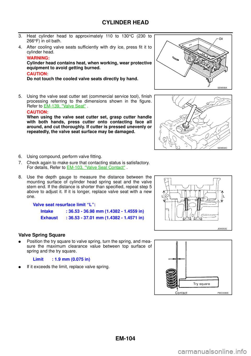
3. Heat cylinder head to approximately 110 to 130°C(230to
266°F) in oil bath.
4. After cooling valve seats sufficiently with dry ice, press fit it to
cylinder head.
WARNING:
Cylinder head contains heat, when working, wear protective
equipment to avoid getting burned.
CAUTION:
Do not touch the cooled valve seats directly by hand.
5. Using the valve seat cutter set (commercial service tool), finish
processing referring to the dimensions shown in the figure.
Refer toEM-139, "
Va l v e S e a t".
CAUTION:
When using the valve seat cutter set, grasp cutter handle
with both hands, press cutter onto contacting face all
around, and cut thoroughly. If cutter is pressed unevenly or
repeatedly, the valve seat surface may be damaged.
6. Using compound, perform valve fitting.
7. Check again to make sure that contacting status is satisfactory.
For details, Refer toEM-103, "
Valve Seat Contact".
8. Use the depth gauge to measure the distance between the
mounting surface of cylinder head spring seat and the valve
stem end. If the distance is shorter than specified, repeat step 5
above to adjust it. If it is longer, replace valve seat with a new
one.
Valve Spring Square
lPosition the try square to valve spring, turn the spring, and mea-
sure the maximum clearance value between top surface of
spring and the try square.
lIf it exceeds the limit, replace valve spring.
SEM008A
SEM934C
Valve seat resurface limit “L”:
Intake : 36.53 - 36.98 mm (1.4382 - 1.4559 in)
Exhaust : 36.53 - 37.01 mm (1.4382 - 1.4571 in)
JEM253G
Limit : 1.9 mm (0.075 in)
PBIC0080E
Page 1487 of 3171
CYLINDER HEAD
EM-105
C
D
E
F
G
H
I
J
K
L
MA
EM
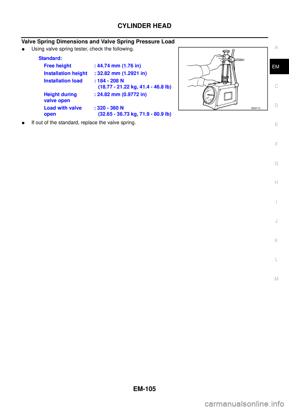
Valve Spring Dimensions and Valve Spring Pressure Load
lUsing valve spring tester, check the following.
lIf out of the standard, replace the valve spring.Standard:
Free height : 44.74 mm (1.76 in)
Installation height : 32.82 mm (1.2921 in)
Installation load : 184 - 208 N
(18.77 - 21.22 kg, 41.4 - 46.8 lb)
Height during
valve open: 24.82 mm (0.9772 in)
Load with valve
open:320-360N
(32.65 - 36.73 kg, 71.9 - 80.9 lb)
SEM113
Page 1488 of 3171
EM-106
ENGINE ASSEMBLY
ENGINE ASSEMBLY
PFP:10001
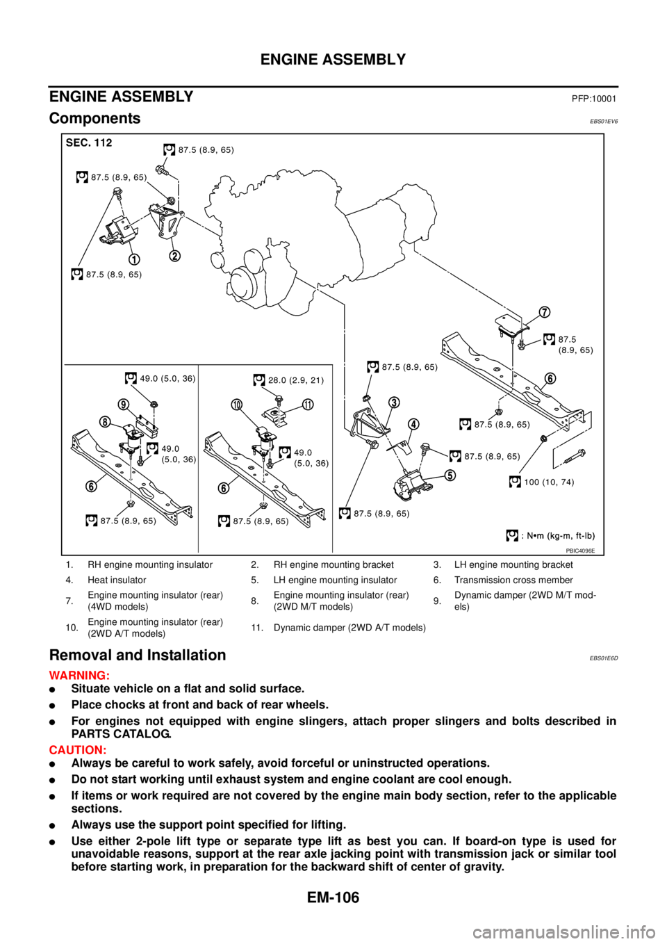
ComponentsEBS01EV6
Removal and InstallationEBS01E6D
WARNING:
lSituate vehicle on a flat and solid surface.
lPlace chocks at front and back of rear wheels.
lFor engines not equipped with engine slingers, attach proper slingers and bolts described in
PARTS CATALOG.
CAUTION:
lAlways be careful to work safely, avoid forceful or uninstructed operations.
lDo not start working until exhaust system and engine coolant are cool enough.
lIf items or work required are not covered by the engine main body section, refer to the applicable
sections.
lAlways use the support point specified for lifting.
lUse either 2-pole lift type or separate type lift as best you can. If board-on type is used for
unavoidable reasons, support at the rear axle jacking point with transmission jack or similar tool
before starting work, in preparation for the backward shift of center of gravity.
1. RH engine mounting insulator 2. RH engine mounting bracket 3. LH engine mounting bracket
4. Heat insulator 5. LH engine mounting insulator 6. Transmission cross member
7.Engine mounting insulator (rear)
(4WD models)8.Engine mounting insulator (rear)
(2WD M/T models)9.Dynamic damper (2WD M/T mod-
els)
10.Engine mounting insulator (rear)
(2WD A/T models)11. Dynamic damper (2WD A/T models)
PBIC4096E
Page 1489 of 3171
ENGINE ASSEMBLY
EM-107
C
D
E
F
G
H
I
J
K
L
MA
EM
lFor supporting points for lifting and jacking point at rear axle, refer toGI-52, "Pantograph Jack,
Garage Jack and Safety Stand".
REMOVAL
Description of work
Remove transmission assembly from vehicle downward. Then hoist the engine from vehicle upward.
Preparation
1. Disconnect battery cable from negative terminal. Refer toSC-5, "BATTERY".
2. Drain engine coolant from radiator drain plug. Refer toCO-7, "
Changing Engine Coolant".
3. Remove the following parts.
lEngine undercover front, engine undercover middle, engine undercover rear; Refer toEI-15, "FRONT
BUMPER".
lHood assembly; Refer toBL-12, "HOOD".
lEngine cover; Refer toEM-20, "INTAKE MANIFOLD".
lDrive belts; Refer toEM-12, "DRIVE BELTS".
lCooling fan, fan coupling and water pump pulley; Refer toCO-19, "COOLING FAN".
lAir duct and air cleaner case; Refer toEM-15, "AIR CLEANER AND AIR DUCT".
lAir inlet tube and air inlet hose; Refer toEM-18, "CHARGE AIR COOLER".
lAlternator; Refer toSC-23, "Removal and Installation".
lRadiator, radiator shroud (upper and lower) and cooling fan assembly; Refer toCO-11, "RADIATOR"
andCO-19, "COOLING FAN".
4. Disconnect engine room harness from the engine side and set it aside for easier work.
5. Disconnect all the body-side vacuum hoses and air hoses at engine side.
Engine room RH
1. Disconnect fuel feed hose and return hose, and plug it to prevent fuel from draining. Refer toEM-44,
"INJECTION TUBE AND FUEL INJECTOR".
2. Remove fuel filter. Refer toFL-4, "
FUEL FILTER".
3. Disconnect heater hose, and install plug it to prevent engine coolant from draining. Refer toCO-23,
"THERMOSTAT AND WATER PIPING".
Engine room LH
1. Remove A/C compressor with piping connected from engine. Temporarily secure it on body with a rope to
avoid putting load on it. Refer toATC-142, "
Removal and Installation for Compressor"(automatic A/C
models) orMTC-122, "
Removal and Installation for Compressor"(manual A/C models).
Vehicle underbody
1. Remove exhaust front tube. Refer toEX-3, "Removal and Installation".
2. Remove front propeller shaft (4WD models) and rear propeller shaft. Refer toPR-3, "
FRONT PROPEL-
LER SHAFT"(4WD models) andPR-7, "REAR PROPELLER SHAFT".
3. Remove clutch operating cylinder from transmission, and move it aside (M/T models). Refer toMT-16,
"TRANSMISSION ASSEMBLY"andCL-11, "OPERATING CYLINDER".
4. Disconnect power steering fluid piping at a point between body and engine. Refer toPS-30, "
HYDRAULIC
LINE".
5. Remove starter motor. Refer toSC-31, "
Removal and Installation".
6. Remove transmission assembly. Refer toMT-16, "
TRANSMISSION ASSEMBLY"(M/T models) orAT-
247, "TRANSMISSION ASSEMBLY"(A/T models).
Page 1490 of 3171
EM-108
ENGINE ASSEMBLY
Removal
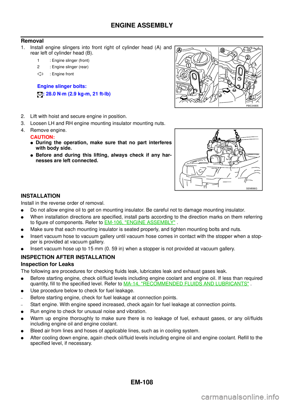
1. Install engine slingers into front right of cylinder head (A) and
rear left of cylinder head (B).
2. Lift with hoist and secure engine in position.
3. Loosen LH and RH engine mounting insulator mounting nuts.
4. Remove engine.
CAUTION:
lDuring the operation, make sure that no part interferes
with body side.
lBefore and during this lifting, always check if any har-
nesses are left connected.
INSTALLATION
Install in the reverse order of removal.
lDo not allow engine oil to get on mounting insulator. Be careful not to damage mounting insulator.
lWhen installation directions are specified, install parts according to the direction marks on them referring
to figure of components. Refer toEM-106, "
ENGINE ASSEMBLY".
lMake sure that each mounting insulator is seated properly, and tighten mounting bolts and nuts.
lInsert vacuum hose to vacuum gallery until vacuum hose comes in contact with the stopper when a stop-
per is provided at vacuum gallery.
lInsert vacuum hose up to 15 mm (0. 59 in) when a stopper is not provided at vacuum gallery.
INSPECTION AFTER INSTALLATION
Inspection for Leaks
The following are procedures for checking fluids leak, lubricates leak and exhaust gases leak.
lBefore starting engine, check oil/fluid levels including engine coolant and engine oil. If less than required
quantity, fill to the specified level. Refer toMA-14, "
RECOMMENDED FLUIDS AND LUBRICANTS".
lUse procedure below to check for fuel leakage.
–Before starting engine, check for fuel leakage at connection points.
–Start engine. With engine speed increased, check again for fuel leakage at connection points.
lRun engine to check for unusual noise and vibration.
lWarm up engine thoroughly to make sure there is no leakage of fuel, exhaust gases, or any oil/fluids
including engine oil and engine coolant.
lBleed air from lines and hoses of applicable lines, such as in cooling system.
lAfter cooling down engine, again check oil/fluid levels including engine oil and engine coolant. Refill to the
specified level, if necessary.
1 : Engine slinger (front)
2 : Engine slinger (rear)
: Engine front
Engine slinger bolts:
: 28.0 N·m (2.9 kg-m, 21 ft-lb)
PBIC3480E
SEM896G