NISSAN NAVARA 2005 Repair Workshop Manual
Manufacturer: NISSAN, Model Year: 2005, Model line: NAVARA, Model: NISSAN NAVARA 2005Pages: 3171, PDF Size: 49.59 MB
Page 2241 of 3171

LT-158
INTERIOR ROOM LAMP
4. Touch “INT LAMP” on “SELECT SYSTEM” screen.
WORK SUPPORT
Operation Procedure
1. Touch “INT LAMP” on “SELECT SYSTEM” screen.
2. Touch “WORK SUPPORT” on “SELECT DIAG MODE” screen.
3. Touch “SET I/L D-UNLCK INTCON” on “SELECT WORK ITEM” screen.
4. Touch “START”.
5. Touch “CHANGE SETT”.
6. The setting will be changed and “CUSTOMIZING COMPLETED” will be displayed.
7. Touch “END”.
Display Item List
Reference between “MODE” and “TIME” for “TURN ON/OFF”.
DATA MONITOR
Operation Procedure
1. Touch “INT LAMP” on “SELECT TEST ITEM” screen.
2. Touch “DATA MONITOR” on “SELECT DIAG MODE” screen.
3. Touch either “ALL SIGNALS” or “SELECTION FROM MENU” on “SELECT MONITOR ITEM” screen.
4. When “ALL SIGNALS” is selected, all the items will be monitored. When “SELECTION FROM MENU” is
selected, touch items to be monitored.
5. Touch “START”.
6. Touch “RECORD” while monitoring, then the status of the monitored item can be recorded. To stop
recording, touch “STOP”.
PKIC0325E
Item Description CONSULT-II
SET I/L D-UNLCK INTCONThe 30 seconds operating function of the interior room lamps and the ignition key-
hole illumination can be selected when driver's door is released (unlocked).ON/OFF
ROOM LAMP ON TIME SETThe time in order to escalate illumination can be selected when the interior room
lamps and the ignition keyhole illumination is turned on.MODE 1 - 7
ROOM LAMP OFF TIME SETThe time in order to diminish illumination can be selected when the interior room
lamps and the ignition keyhole illumination is turned off.MODE 1 - 7
MODE 1 2 3 4 5 6 7
Time (sec.) 0.5 1 2 3 4 5 0
ALL SIGNALS Monitors all the signals.
SELECTION FROM MENU Selects and monitors the individual signal.
Page 2242 of 3171

INTERIOR ROOM LAMP
LT-159
C
D
E
F
G
H
I
J
L
MA
B
LT
Display Item List
ACTIVE TEST
Operation Procedure
1. Touch “INT LAMP” on “SELECT TEST ITEM” screen.
2. Touch “ACTIVE TEST” on “SELECT DIAG MODE” screen.
3. Touch item to be tested and check operation of the selected item.
4. During the operation check, touching “OFF” deactivates the operation.
Display Item List
Monitor item Contents
IGN ON SW “ON/OFF” Displays “IGN position (ON)/OFF, ACC position (OFF)” judged from the ignition switch signal.
KEY ON SW “ON/OFF” Displays “Key inserted (ON)/key removed (OFF)” status judged from the key switch signal.
DOOR SW-DR “ON/OFF”Displays status of the driver's door as judged from the driver door switch signal. (Door is open:
ON/Door is closed: OFF)
DOOR SW-AS “ON/OFF”Displays “Door open (ON)/Door closed (OFF)” status, determined from passenger's door switch
signal.
DOOR SW-RR “ON/OFF”Displays “Door open (ON)/Door closed (OFF)” status, determined from rear door switch RH sig-
nal.
DOOR SW-RL “ON/OFF”Displays “Door open (ON)/Door closed (OFF)” status, determined from rear door switch LH sig-
nal.
BACK DOOR SW “ON/OFF” Displays “Door open (ON)/Door closed (OFF)” status, determined from back door switch signal.
KEY CYL LK-SW “ON/OFF” Displays “Door locked (ON)” status, determined from key cylinder lock switch in driver door.
KEY CYL UN-SW “ON/OFF” Displays “Door unlocked (OFF)” status, determined from key cylinder lock switch in driver door.
CDL LOCK SW “ON/OFF”Displays “Door locked (ON)/Door unlocked (OFF)” status, determined from locking detection
switch in driver door.
CDL UNLOCK SW “ON/OFF”Displays “Door unlocked (OFF)” status, determined from locking detection switch in passenger
door.
Test item Description
INT LAMP Interior room lamp can be operated by any ON-OFF operations.
Page 2243 of 3171
LT-160
INTERIOR ROOM LAMP
Map Lamp Control Does Not Operate
EKS00P9A
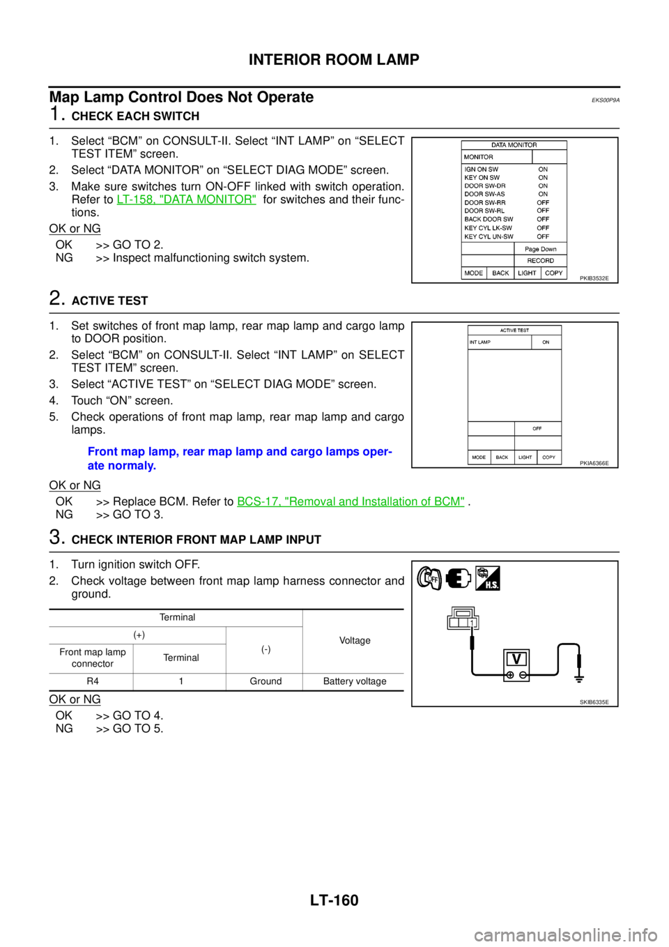
1.CHECK EACH SWITCH
1. Select “BCM” on CONSULT-II. Select “INT LAMP” on “SELECT
TEST ITEM” screen.
2. Select “DATA MONITOR” on “SELECT DIAG MODE” screen.
3. Make sure switches turn ON-OFF linked with switch operation.
Refer toLT- 1 5 8 , "
DATA MONITOR"for switches and their func-
tions.
OK or NG
OK >> GO TO 2.
NG >> Inspect malfunctioning switch system.
2.ACTIVE TEST
1. Set switches of front map lamp, rear map lamp and cargo lamp
to DOOR position.
2. Select “BCM” on CONSULT-II. Select “INT LAMP” on SELECT
TEST ITEM” screen.
3. Select “ACTIVE TEST” on “SELECT DIAG MODE” screen.
4. Touch “ON” screen.
5. Check operations of front map lamp, rear map lamp and cargo
lamps.
OK or NG
OK >> Replace BCM. Refer toBCS-17, "Removal and Installation of BCM".
NG >> GO TO 3.
3.CHECK INTERIOR FRONT MAP LAMP INPUT
1. Turn ignition switch OFF.
2. Check voltage between front map lamp harness connector and
ground.
OK or NG
OK >> GO TO 4.
NG >> GO TO 5.
PKIB3532E
Front map lamp, rear map lamp and cargo lamps oper-
ate normaly.PKIA6366E
Terminal
Voltage (+)
(-)
Front map lamp
connectorTerminal
R4 1 Ground Battery voltage
SKIB6335E
Page 2244 of 3171
INTERIOR ROOM LAMP
LT-161
C
D
E
F
G
H
I
J
L
MA
B
LT
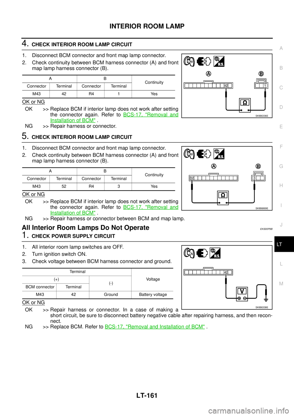
4.CHECK INTERIOR ROOM LAMP CIRCUIT
1. Disconnect BCM connector and front map lamp connector.
2. Check continuity between BCM harness connector (A) and front
map lamp harness connector (B).
OK or NG
OK >> Replace BCM if interior lamp does not work after setting
the connector again. Refer toBCS-17, "
Removal and
Installation of BCM".
NG >> Repair harness or connector.
5.CHECK INTERIOR ROOM LAMP CIRCUIT
1. Disconnect BCM connector and front map lamp connector.
2. Check continuity between BCM harness connector (A) and front
map lamp harness connector (B).
OK or NG
OK >> Replace BCM if interior lamp does not work after setting
the connector again. Refer toBCS-17, "
Removal and
Installation of BCM".
NG >> Repair harness or connector between BCM and map lamp.
All Interior Room Lamps Do Not OperateEKS00P9B
1.CHECK POWER SUPPLY CIRCUIT
1. All interior room lamp switches are OFF.
2. Turn ignition switch ON.
3. Check voltage between BCM harness connector and ground.
OK or NG
OK >> Repair harness or connector. In a case of making a
short circuit, be sure to disconnect battery negative cable after repairing harness, and then recon-
nect.
NG >> Replace BCM. Refer toBCS-17, "
Removal and Installation of BCM".
AB
Continuity
Connector Terminal Connector Terminal
M43 42 R4 1 Yes
SKIB6336E
AB
Continuity
Connector Terminal Connector Terminal
M43 52 R4 3 Yes
SKIB6869E
Te r m i n a l
Voltage (+)
(-)
BCM connector Terminal
M43 42 Ground Battery voltage
SKIB6338E
Page 2245 of 3171

LT-162
ILLUMINATION
ILLUMINATION
PFP:27545
System DescriptionEKS00P8V
Control of the illumination lamps operation is dependent upon the position of the lighting switch (combination
switch). When the lighting switch is placed in the 1ST position, 2ND position or AUTO position (headlamp is
ON) the BCM (body control module) receives input signal requesting the illumination lamps to illuminate. This
input signal is communicated to the IPDM E/R (intelligent power distribution module engine room) through the
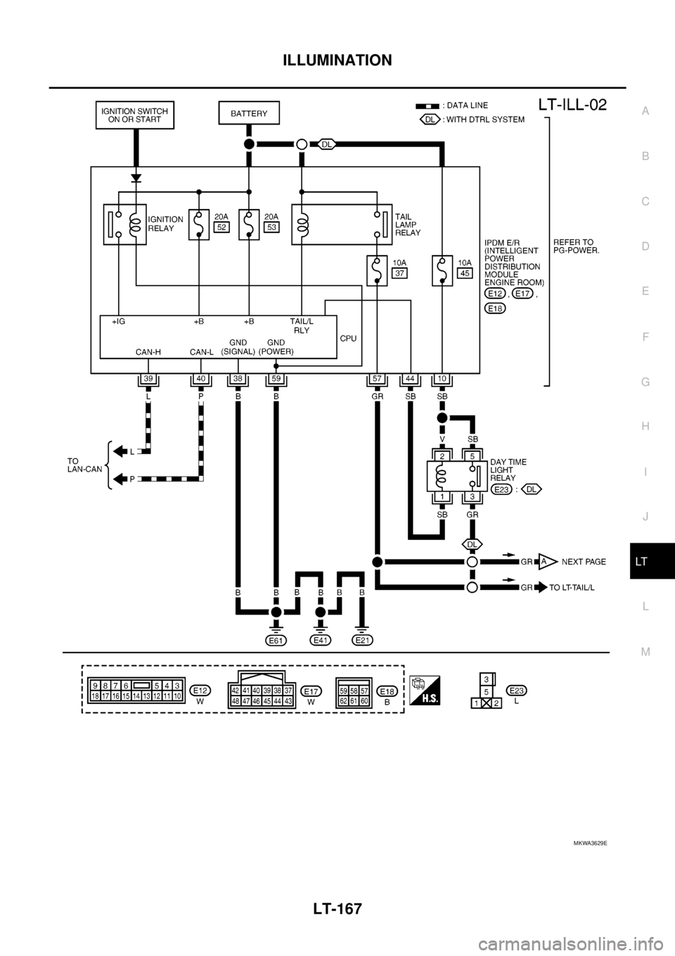
CAN communication. The CPU (central processing unit) of the IPDM E/R controls the tail lamp relay coil. This
relay, when energized, directs power to the illumination lamps, which then illuminate.
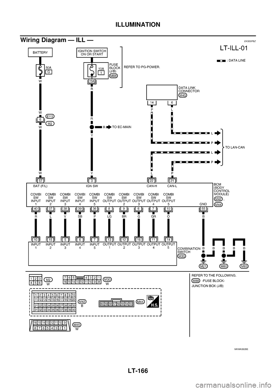
Power is supplied at all times
lto ignition relay (located in IPDM E/R) and
lto tail lamp relay (located in IPDM E/R), from battery directly,
lthrough 50A fusible link (letter G, located in fuse and fusible link box)
lto BCM terminal 57,
lthrough 20A fuse (No. 52, located in IPDM E/R) and
lthrough 20A fuse (No. 53, located in IPDM E/R)
lto CPU (located in IPDM E/R),
lthrough 10A fuse [No.19, located in fuse block (J/B)]
lto combination meter terminal 3.
With the ignition switch in the ON or START position, power is supplied
lto ignition relay (located in IPDM E/R),
lthrough 10A fuse [No. 1, located in fuse block (J/B)]
lto BCM terminal 3,
lthrough 10A fuse [No. 14, located in fuse block (J/B)]
lto combination meter 16.
Ground is supplied
lto BCM terminal 55 and
lto combination meter terminal 23
lthrough grounds M21, M80 and M83,
lto IPDM E/R terminals 38 and 59
lthrough grounds E21, E41 and E61.
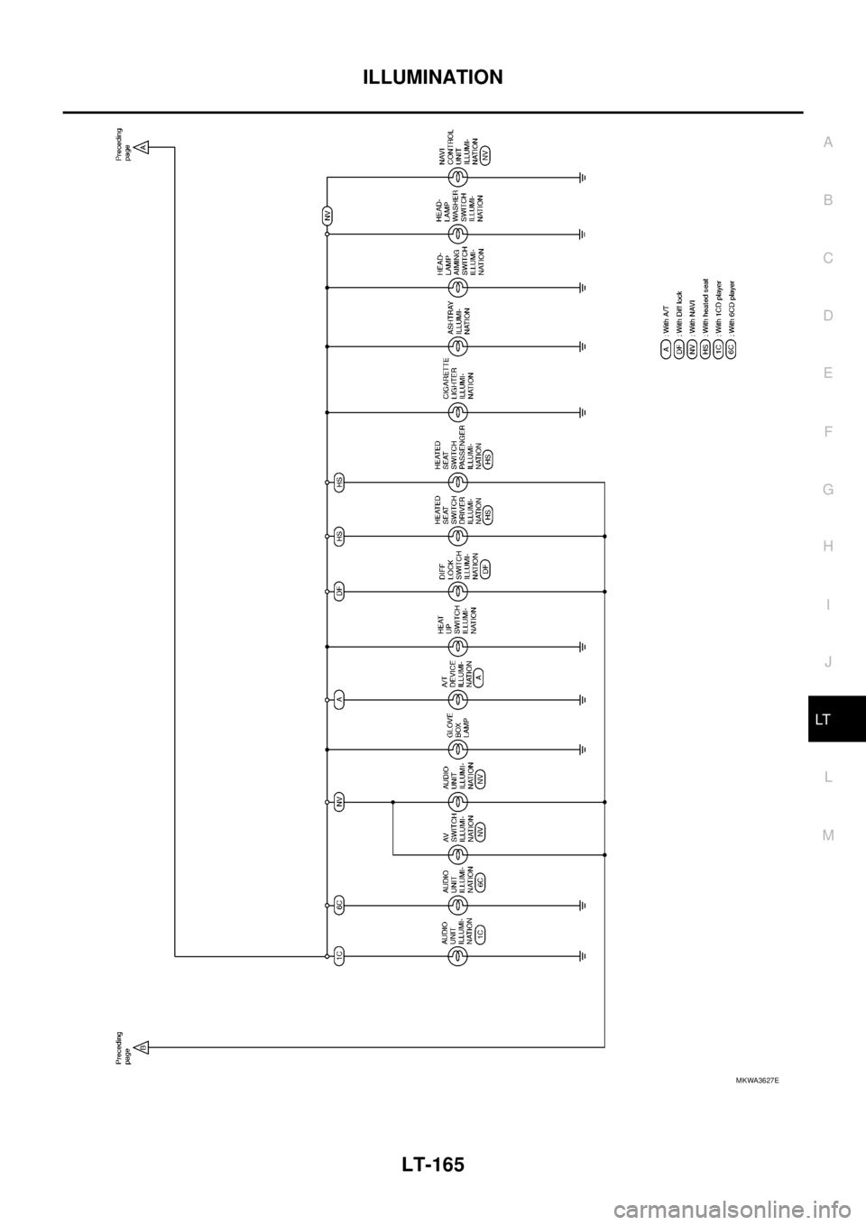
ILLUMINATION OPERATION BY LIGHTING SWITCH
With the lighting switch in the 1ST position, 2ND position or AUTO position (headlamp is ON), the BCM
receives input signal requesting the illumination lamps to illuminate. This input signal is communicated to the
IPDM E/R through the CAN communication. The CPU of the IPDM E/R controls the tail lamp relay coil, which,
when energized, directs power
lthrough 10A fuse (No. 37, located in IPDM E/R)
lthrough IPDM E/R terminal 57
lto hazard switch (illumination) terminal 3
lto 4WD shift switch (illumination) terminal 7 (with 4-wheel drive)
lto front air control (illumination) terminal 8
lto audio unit (illumination) terminal 2 (1CD player)
lto audio unit (illumination) terminal 8 (6CD player)
lto AV switch (illumination) terminal 3 (with NAVI)
lto audio unit (illumination) terminal 29 (with NAVI)
lto glove box lamp terminal 1
lto A/T device (illumination) terminal 3 (with A/T)
lto heat up switch (illumination) terminal 5
lto DIFF LOCK switch (illumination) terminal 4 (with DIFF LOCK)
lto heated seat switch (driver side) (illumination) terminal 5 (with heated seats)
lto heated seat switch (passenger side) (illumination) terminal 5 (with heated seats)
Page 2246 of 3171
ILLUMINATION
LT-163
C
D
E
F
G
H
I
J
L
MA
B
LT
lto cigarette lighter (illumination) terminal 1
lto ashtray (illumination) terminal 1
lto headlamp washer switch (illumination) terminal 3
lto headlamp aiming switch (illumination) terminal 3 and
lto NAVI control unit (illumination) terminal 61 (with NAVI).
Ground is supplied
lto hazard switch (illumination) terminal 4
lto 4WD shift switch (illumination) terminal 8 (with 4-wheel drive)
lto front air control (illumination) terminal 9
lto AV switch (illumination) terminal 4 (with NAVI)
lto audio unit (illumination) terminal 28 (with NAVI)
lto DIFF LOCK switch (illumination) terminal 5 (with DIFF LOCK)
lto heated seat switch (driver side) (illumination) terminal 6 (with heated seats) and
lto heated seat switch (passenger side) (illumination) terminal 6 (with heated seats)
lthrough combination meter terminal 22
lthrough combination meter terminal 23
lthrough ground M21, M80 and M83,
lto glove box lamp terminal 2
lto A/T device (illumination) terminal 5 (with A/T)
lto heat up switch (illumination) terminal 6
lto ashtray (illumination) terminal 2
lto headlamp washer switch (illumination) terminal 4 and
lto headlamp aiming switch (illumination) terminal 4
ltrough ground M21, M80 and M83,
lto audio unit (illumination) (1CD and 6CD player)
lthrough case ground of audio unit,
lto cigarette lighter (illumination)
lthrough case ground of cigarette lighter,
lto NAVI control unit (illumination) terminal 1 (with NAVI)
lthrough ground B106 and B121.
With power and ground supplied, illumination lamps illuminate.
CAN Communication System DescriptionEKS00P8W
Refer toLAN-23, "CAN COMMUNICATION".
CAN Communication UnitEKS00P8X
Refer toLAN-30, "CAN Communication Unit".
Page 2247 of 3171
LT-164
ILLUMINATION
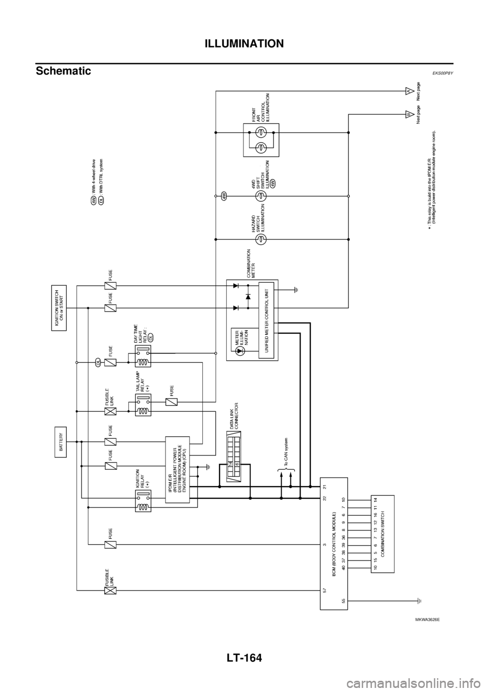
Schematic
EKS00P8Y
MKWA3626E
Page 2248 of 3171
ILLUMINATION
LT-165
C
D
E
F
G
H
I
J
L
MA
B
LT
MKWA3627E
Page 2249 of 3171
LT-166
ILLUMINATION
Wiring Diagram — ILL —
EKS00P8Z
MKWA3628E
Page 2250 of 3171
ILLUMINATION
LT-167
C
D
E
F
G
H
I
J
L
MA
B
LT
MKWA3629E