NISSAN NAVARA 2005 Repair Workshop Manual
NAVARA 2005
NISSAN
NISSAN
https://www.carmanualsonline.info/img/5/57362/w960_57362-0.png
NISSAN NAVARA 2005 Repair Workshop Manual
Trending: immobilizer, glove box, Engine lubrication system, clutch, wiring diagram, fuel consumption, oil change
Page 2231 of 3171
LT-148
INTERIOR ROOM LAMP
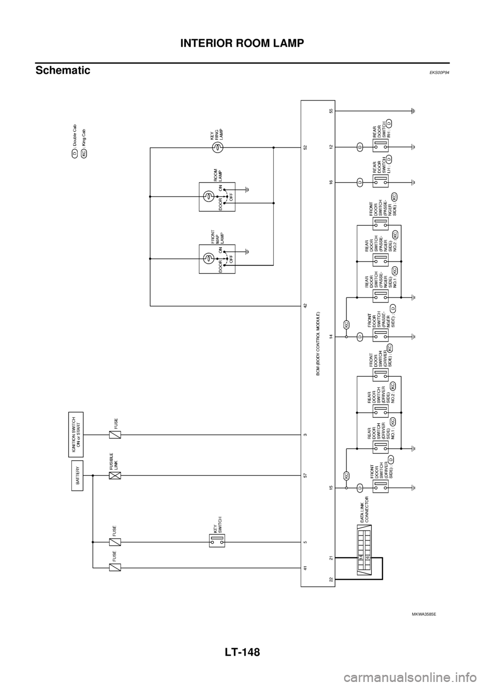
Schematic
EKS00P94
MKWA3585E
Page 2232 of 3171
INTERIOR ROOM LAMP
LT-149
C
D
E
F
G
H
I
J
L
MA
B
LT
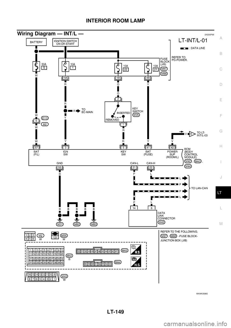
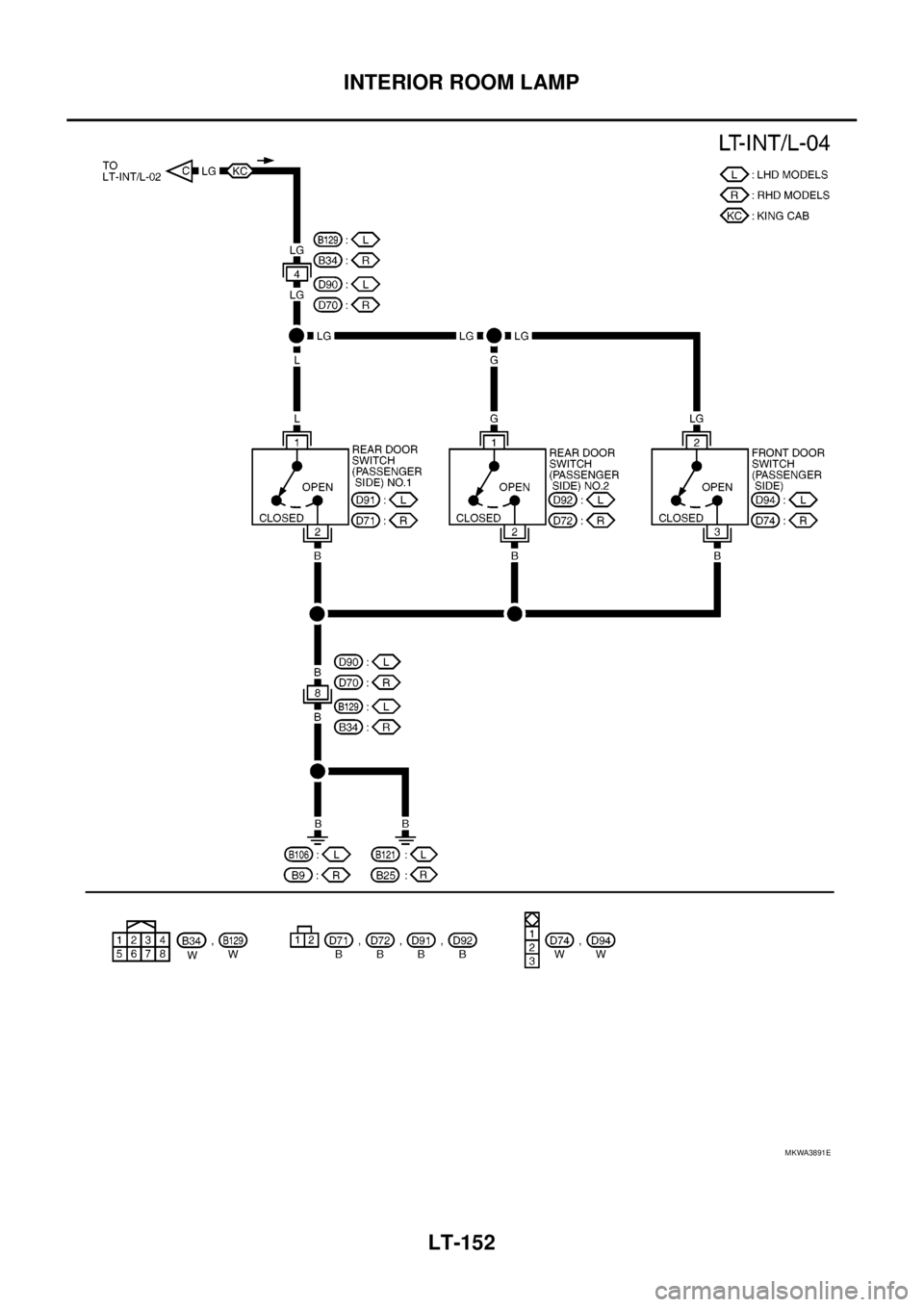
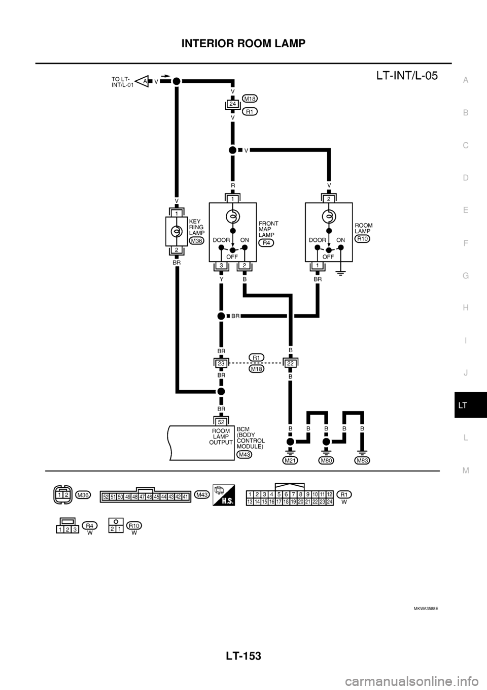
Wiring Diagram — INT/L —EKS00P95
MKWA3586E
Page 2233 of 3171
LT-150
INTERIOR ROOM LAMP
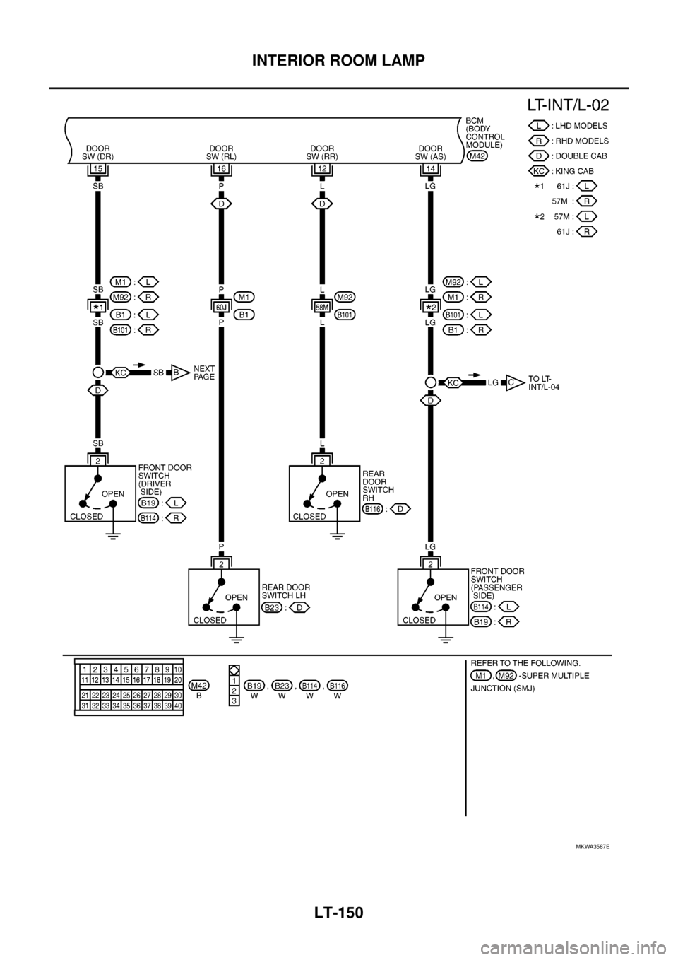
MKWA3587E
Page 2234 of 3171
INTERIOR ROOM LAMP
LT-151
C
D
E
F
G
H
I
J
L
MA
B
LT
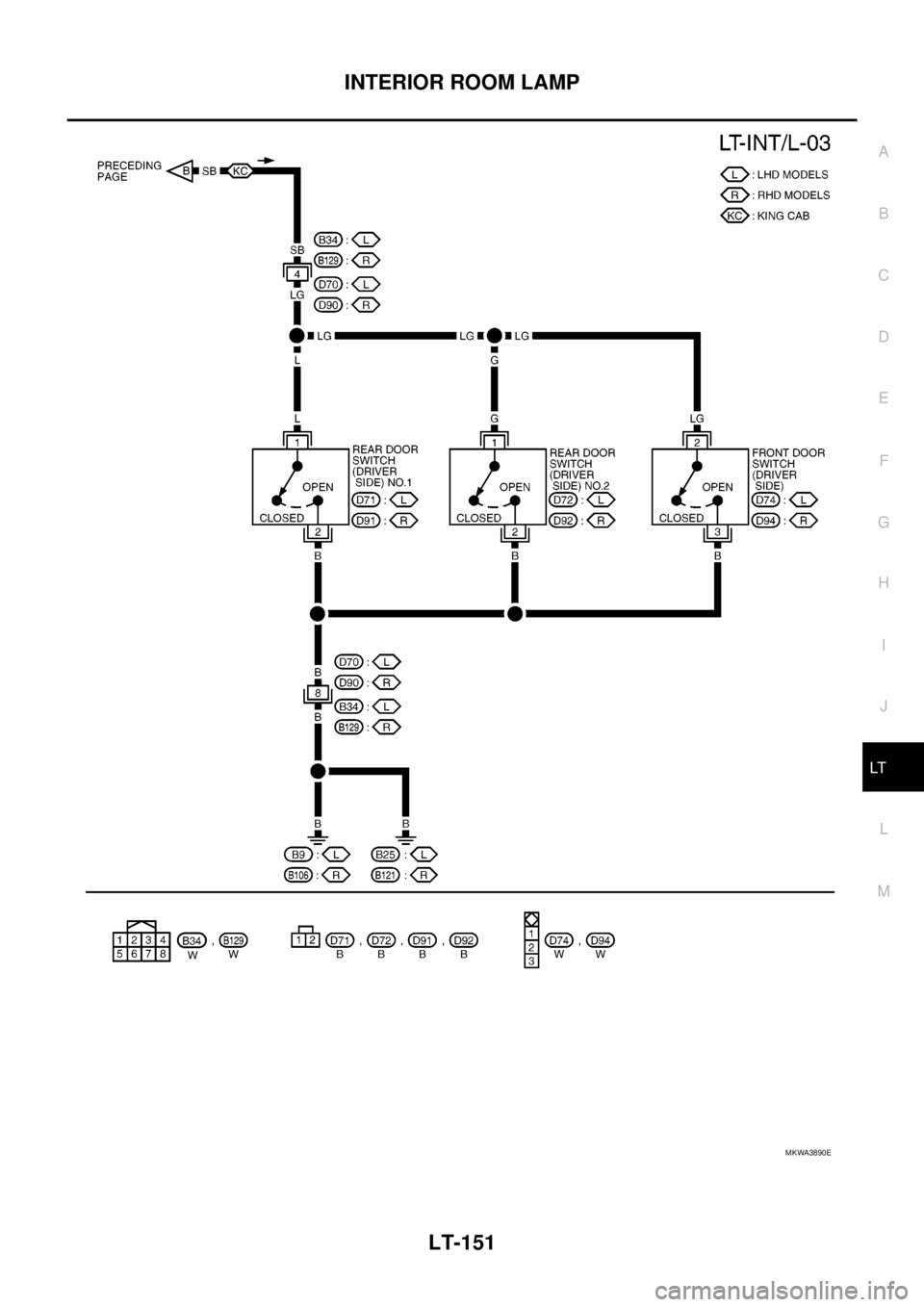
MKWA3890E
Page 2235 of 3171
LT-152
INTERIOR ROOM LAMP
MKWA3891E
Page 2236 of 3171
INTERIOR ROOM LAMP
LT-153
C
D
E
F
G
H
I
J
L
MA
B
LT
MKWA3588E
Page 2237 of 3171
LT-154
INTERIOR ROOM LAMP
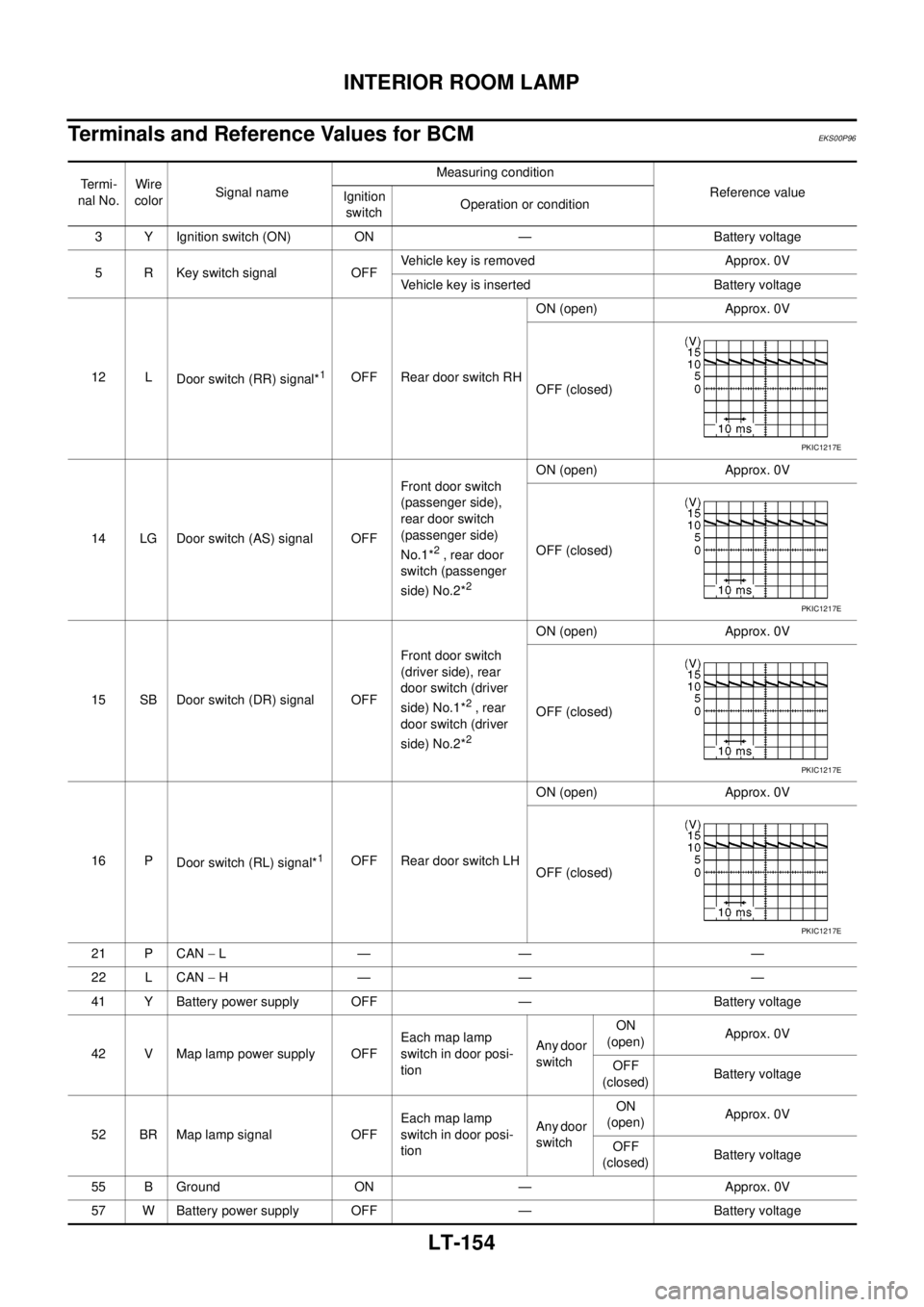
Terminals and Reference Values for BCM
EKS00P96
Te r m i -
nal No.Wire
colorSignal nameMeasuring condition
Reference value
Ignition
switchOperation or condition
3 Y Ignition switch (ON) ON — Battery voltage
5 R Key switch signal OFFVehicle key is removed Approx. 0V
Vehicle key is inserted Battery voltage
12 L
Door switch (RR) signal*
1OFF Rear door switch RHON (open) Approx. 0V
OFF (closed)
14 LG Door switch (AS) signal OFFFront door switch
(passenger side),
rear door switch
(passenger side)
No.1*
2, rear door
switch (passenger
side) No.2*
2
ON (open) Approx. 0V
OFF (closed)
15 SB Door switch (DR) signal OFFFront door switch
(driver side), rear
door switch (driver
side) No.1*
2, rear
door switch (driver
side) No.2*
2
ON (open) Approx. 0V
OFF (closed)
16 P
Door switch (RL) signal*
1OFF Rear door switch LHON (open) Approx. 0V
OFF (closed)
21 P CAN-L— — —
22 L CAN-H— — —
41 Y Battery power supply OFF — Battery voltage
42 V Map lamp power supply OFFEach map lamp
switch in door posi-
tionAny door
switchON
(open)Approx. 0V
OFF
(closed)Battery voltage
52 BR Map lamp signal OFFEach map lamp
switch in door posi-
tionAny door
switchON
(open)Approx. 0V
OFF
(closed)Battery voltage
55 B Ground ON — Approx. 0V
57 W Battery power supply OFF — Battery voltage
PKIC1217E
PKIC1217E
PKIC1217E
PKIC1217E
Page 2238 of 3171
INTERIOR ROOM LAMP
LT-155
C
D
E
F
G
H
I
J
L
MA
B
LT
*1: Double cab, *2: King cab
How to Proceed With Trouble DiagnosisEKS00P97
1. Confirm the symptom or customer complaint.
2. Understand operation description and function description. Refer toLT- 1 4 5 , "
System Description".
3. Carry out the Preliminary Check. Refer toLT- 1 5 5 , "
Preliminary Check".
4. Check symptom and repair or replace the cause of malfunction.
5. Does the interior room lamp operate normally? If YES: GO TO 6. If NO: GO TO 4.
6. INSPECTION END
Preliminary CheckEKS00P98
INSPECTION FOR POWER SUPPLY AND GROUND CIRCUIT
1.CHECK FUSES OR FUSIBLE LINK
Check for blown fuses or fusible link.
Refer toLT-149, "Wiring Diagram—INT/L—".
OK or NG
OK >> GO TO 2.
NG >> If fuse or fusible link is blown, be sure to eliminate cause of malfunction before installing new fuse
or fusible link. Refer toPG-4, "
POWER SUPPLY ROUTING CIRCUIT".
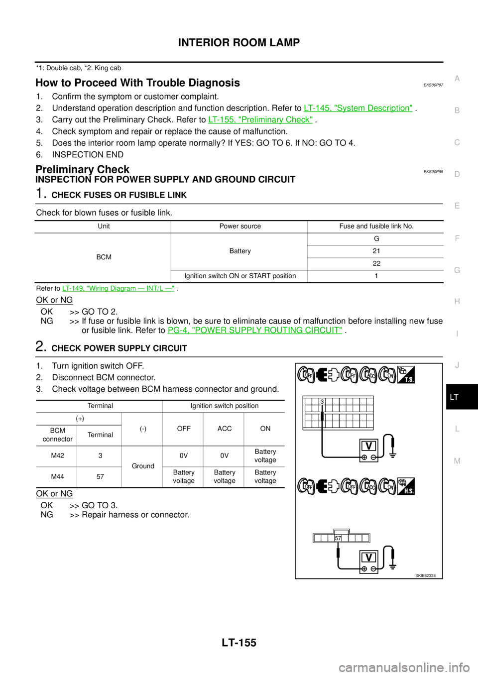
2.CHECK POWER SUPPLY CIRCUIT
1. Turn ignition switch OFF.
2. Disconnect BCM connector.
3. Check voltage between BCM harness connector and ground.
OK or NG
OK >> GO TO 3.
NG >> Repair harness or connector.
Unit Power source Fuse and fusible link No.
BCMBatteryG
21
22
Ignition switch ON or START position 1
Terminal Ignition switch position
(+)
(-) OFF ACC ON
BCM
connectorTerminal
M42 3
Ground0V 0VBattery
voltage
M44 57Battery
voltageBattery
voltageBattery
voltage
SKIB6233E
Page 2239 of 3171
LT-156
INTERIOR ROOM LAMP
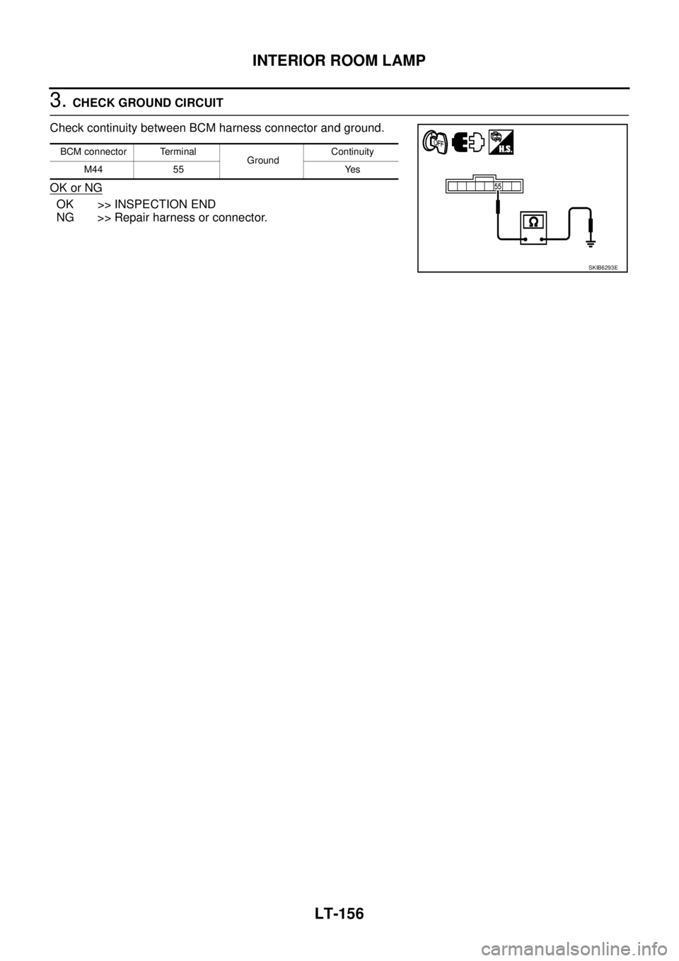
3.CHECK GROUND CIRCUIT
Check continuity between BCM harness connector and ground.
OK or NG
OK >> INSPECTION END
NG >> Repair harness or connector.
BCM connector Terminal
GroundContinuity
M44 55 Yes
SKIB6293E
Page 2240 of 3171
INTERIOR ROOM LAMP
LT-157
C
D
E
F
G
H
I
J
L
MA
B
LT
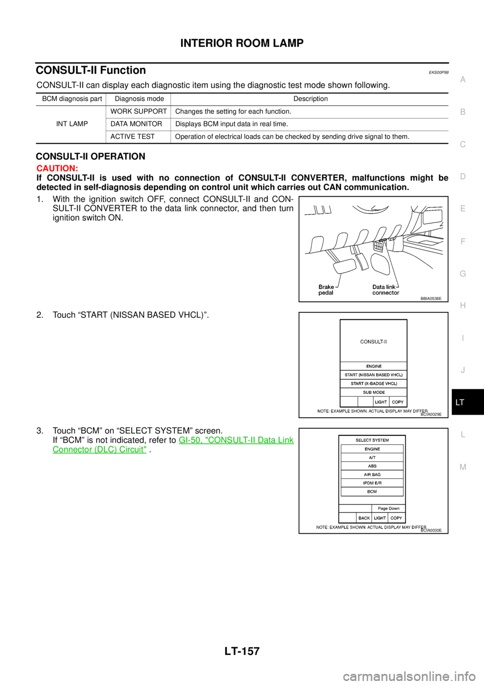
CONSULT-II FunctionEKS00P99
CONSULT-II can display each diagnostic item using the diagnostic test mode shown following.
CONSULT-II OPERATION
CAUTION:
If CONSULT-II is used with no connection of CONSULT-II CONVERTER, malfunctions might be
detected in self-diagnosis depending on control unit which carries out CAN communication.
1. With the ignition switch OFF, connect CONSULT-II and CON-
SULT-II CONVERTER to the data link connector, and then turn
ignition switch ON.
2. Touch “START (NISSAN BASED VHCL)”.
3. Touch “BCM” on “SELECT SYSTEM” screen.
If “BCM” is not indicated, refer toGI-50, "
CONSULT-II Data Link
Connector (DLC) Circuit".
BCM diagnosis part Diagnosis mode Description
INT LAMPWORK SUPPORT Changes the setting for each function.
DATA MONITOR Displays BCM input data in real time.
ACTIVE TEST Operation of electrical loads can be checked by sending drive signal to them.
BBIA0538E
BCIA0029E
BCIA0030E
Trending: wiring, tyre pressure, U1000, parking sensors, turn signal bulb, brake rotor, headlamp
