NISSAN NAVARA 2005 Repair Workshop Manual
Manufacturer: NISSAN, Model Year: 2005, Model line: NAVARA, Model: NISSAN NAVARA 2005Pages: 3171, PDF Size: 49.59 MB
Page 2311 of 3171
MA-36
CHASSIS AND BODY MAINTENANCE
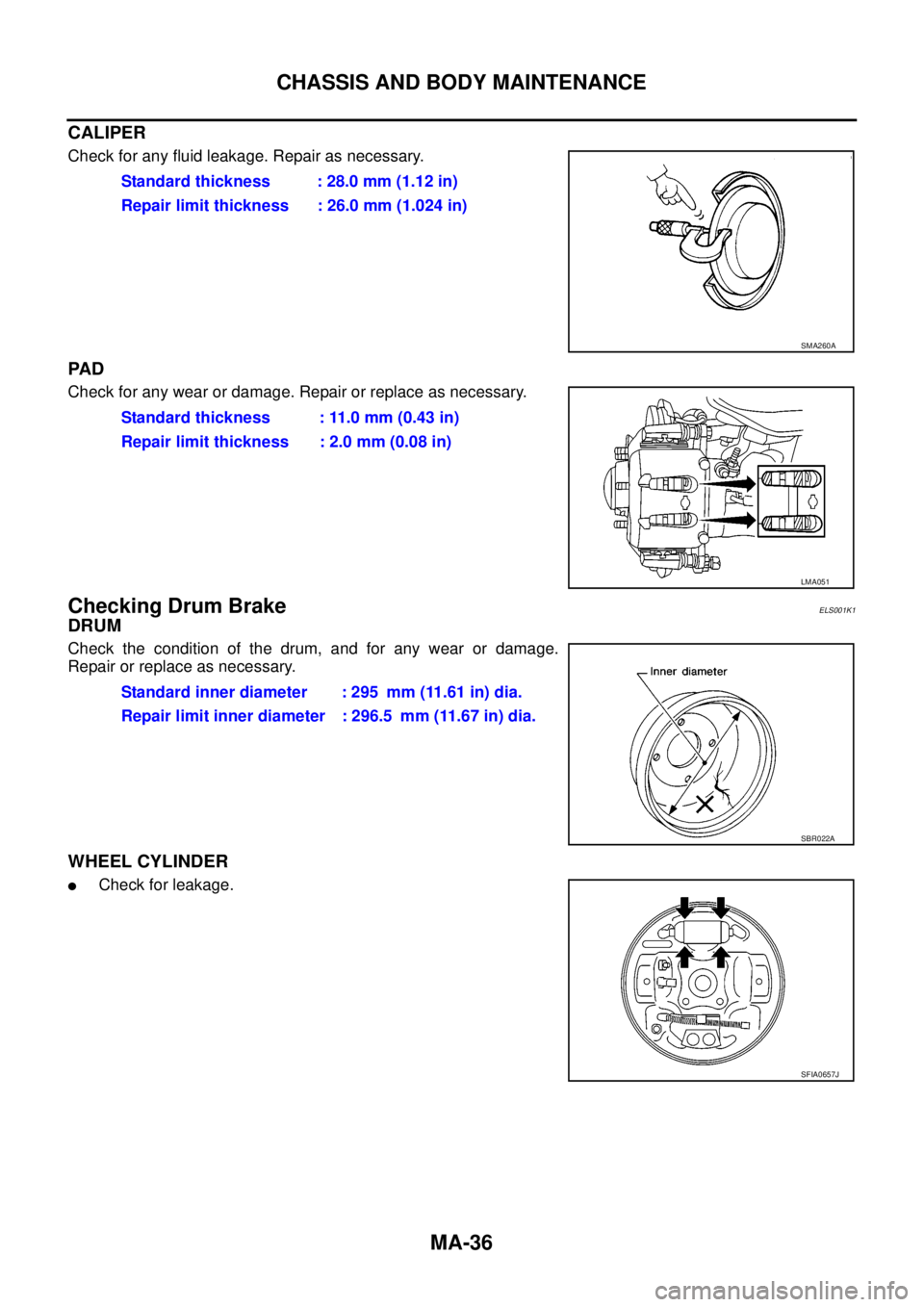
CALIPER
Check for any fluid leakage. Repair as necessary.
PA D
Check for any wear or damage. Repair or replace as necessary.
Checking Drum BrakeELS001K1
DRUM
Check the condition of the drum, and for any wear or damage.
Repair or replace as necessary.
WHEEL CYLINDER
lCheck for leakage.Standard thickness : 28.0 mm (1.12 in)
Repair limit thickness : 26.0 mm (1.024 in)
SMA260A
Standard thickness : 11.0 mm (0.43 in)
Repair limit thickness : 2.0 mm (0.08 in)
LMA051
Standard inner diameter : 295 mm (11.61 in) dia.
Repair limit inner diameter : 296.5 mm (11.67 in) dia.
SBR022A
SFIA0657J
Page 2312 of 3171
CHASSIS AND BODY MAINTENANCE
MA-37
C
D
E
F
G
H
I
J
K
MA
B
MA
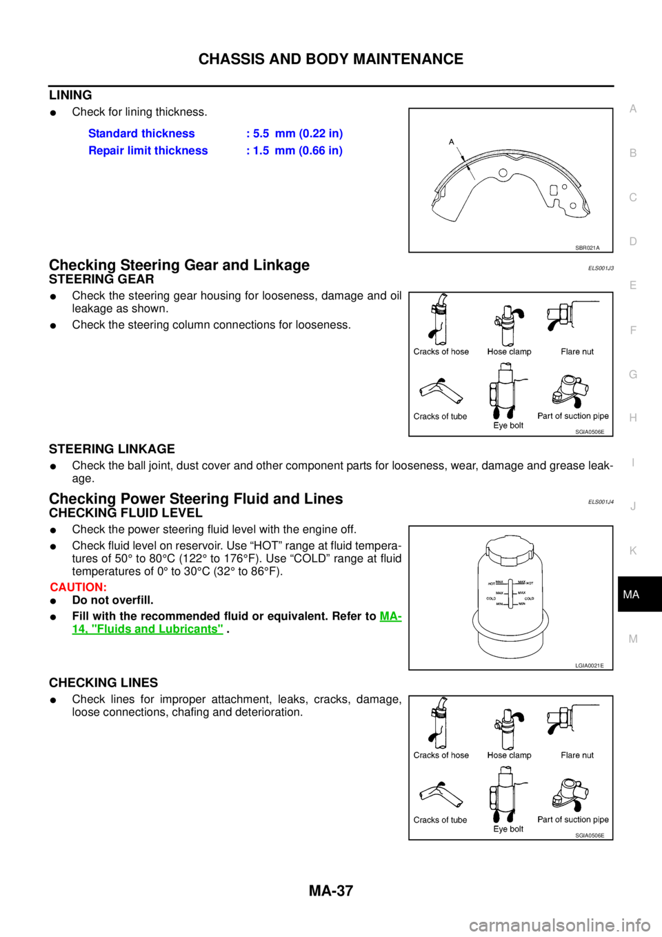
LINING
lCheck for lining thickness.
Checking Steering Gear and LinkageELS001J3
STEERING GEAR
lCheck the steering gear housing for looseness, damage and oil
leakage as shown.
lCheck the steering column connections for looseness.
STEERING LINKAGE
lCheck the ball joint, dust cover and other component parts for looseness, wear, damage and grease leak-
age.
Checking Power Steering Fluid and LinesELS001J4
CHECKING FLUID LEVEL
lCheck the power steering fluid level with the engine off.
lCheck fluid level on reservoir. Use “HOT” range at fluid tempera-
tures of 50°to 80°C(122°to 176°F). Use “COLD” range at fluid
temperatures of 0°to 30°C(32°to 86°F).
CAUTION:
lDo not overfill.
lFill with the recommended fluid or equivalent. Refer toMA-
14, "Fluids and Lubricants".
CHECKING LINES
lCheck lines for improper attachment, leaks, cracks, damage,
loose connections, chafing and deterioration.Standard thickness : 5.5 mm (0.22 in)
Repair limit thickness : 1.5 mm (0.66 in)
SBR021A
SGIA0506E
LGIA0021E
SGIA0506E
Page 2313 of 3171
MA-38
CHASSIS AND BODY MAINTENANCE
Checking Axle and Suspension Parts
ELS001J5
FRONT AND REAR AXLE AND SUSPENSION PARTS
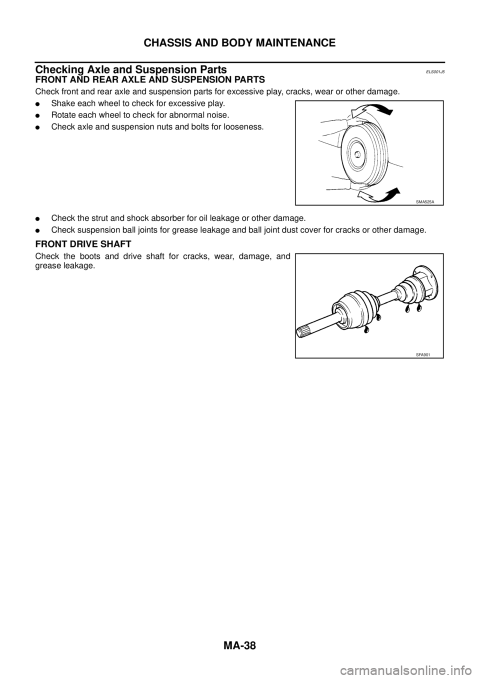
Check front and rear axle and suspension parts for excessive play, cracks, wear or other damage.
lShake each wheel to check for excessive play.
lRotate each wheel to check for abnormal noise.
lCheck axle and suspension nuts and bolts for looseness.
lCheck the strut and shock absorber for oil leakage or other damage.
lCheck suspension ball joints for grease leakage and ball joint dust cover for cracks or other damage.
FRONT DRIVE SHAFT
Check the boots and drive shaft for cracks, wear, damage, and
grease leakage.
SMA525A
SFA901
Page 2314 of 3171
CHASSIS AND BODY MAINTENANCE
MA-39
C
D
E
F
G
H
I
J
K
MA
B
MA
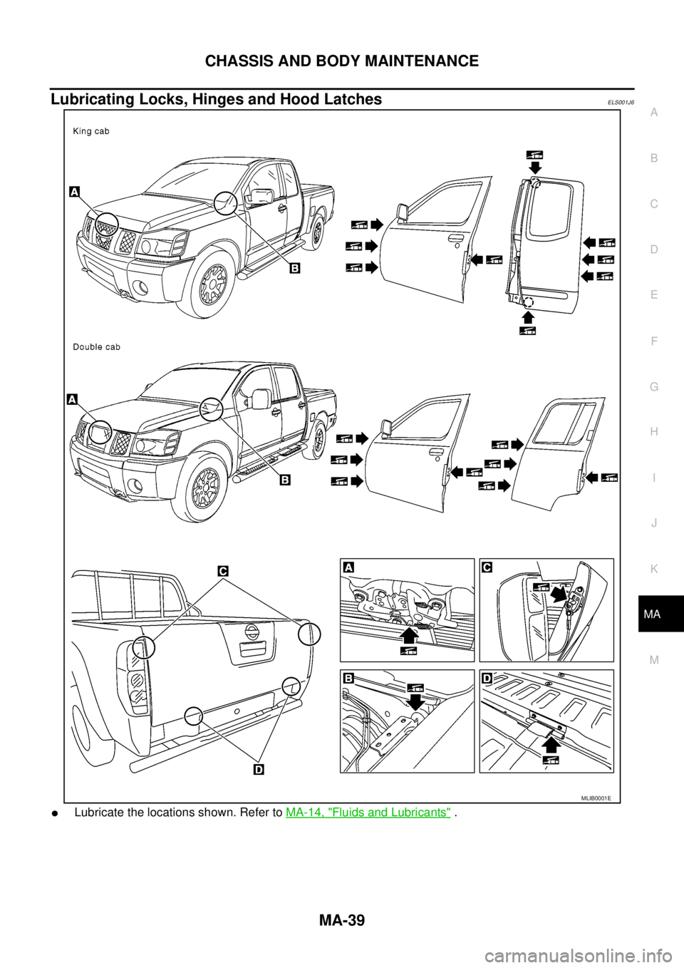
Lubricating Locks, Hinges and Hood LatchesELS001J6
lLubricate the locations shown. Refer toMA-14, "Fluids and Lubricants".
MLIB0001E
Page 2315 of 3171
MA-40
CHASSIS AND BODY MAINTENANCE
Checking Seat Belts, Buckles, Retractors, Anchors and Adjusters
ELS001J7
Check the seat belt buckles, webbing, retractors, anchors and adjusters. Replace any seat belt assembly as
necessary. Refer toSB-11, "
Seat Belt Inspection".
lCheck the seat belt anchors for loose mounting bolts, damage, or excessive wear.
lCheck the seat belt webbing for any damage, cuts, fraying, or excessive wear.
lCheck the retractor for smooth operation.
lCheck the function of the buckles by inserting the seat belt tongue and checking for proper engagement of
the buckle and press the button on the buckle to check for proper release of the seat belt tongue.
CAUTION:
lAfter any collision, inspect all seat belt assemblies, including retractors and other attached com-
ponents, such as the guide rail set. NISSAN recommends replacing all seat belt assemblies in use
during a collision, unless they are not damaged and are inspected to confirm they are operating
properly after a minor collision.
Also inspect all seat belt assemblies that are not in use during a collision, and replace any compo-
nents if damaged or not operating properly. The seat belt pre-tensioner should be replaced even if
the seat belts are not in use during a frontal collision where the driver and passenger air bags
have been deployed.
lIf any component of the seat belt assembly is suspected of being damaged or not operating prop-
erly, do not repair the component. Replace the components as an assembly.
lIf the seat belt webbing is cut, frayed, or damaged then replace the seat belt assembly.
lNever lubricate the seat belt buckle or tongue.
lWhen replacing any seat belt assembly always use a Genuine NISSAN seat belt assembly.
Checking Body CorrosionELS001K3
Visually check body panels for collision damage (scratches, chipping, rubbing, etc.) or damage to the anti-cor-
rosion materials. In particular, check the following locations.
HEMMED PANELS
Hood front end, door lower end, trunk lid rear end, etc.
PANEL JOINT
Side sill of rear fender and center pillar, rear wheel housing of rear fender, around strut tower in engine com-
partment, etc.
PANEL EDGE
Trunk lid opening, sunroof opening, fender wheel-arch flange, fuel filler lid flange, around holes in panel, etc.
PARTS CONTACT
Waist moulding, windshield moulding, bumper, etc.
PROTECTORS
Damage or condition of mudguard, fender protector, chipping protector, etc.
ANTI-CORROSION MATERIALS
Damage or separation of anti-corrosion materials under the body.
DRAIN HOLES
Condition of drain holes at door and side sill. When repairing corroded areas, refer to the Corrosion Repair
Manual.
Page 2316 of 3171
SERVICE DATA AND SPECIFICATIONS (SDS)
MA-41
C
D
E
F
G
H
I
J
K
MA
B
MA
SERVICE DATA AND SPECIFICATIONS (SDS)PFP:00030
Standard and LimitELS001J8
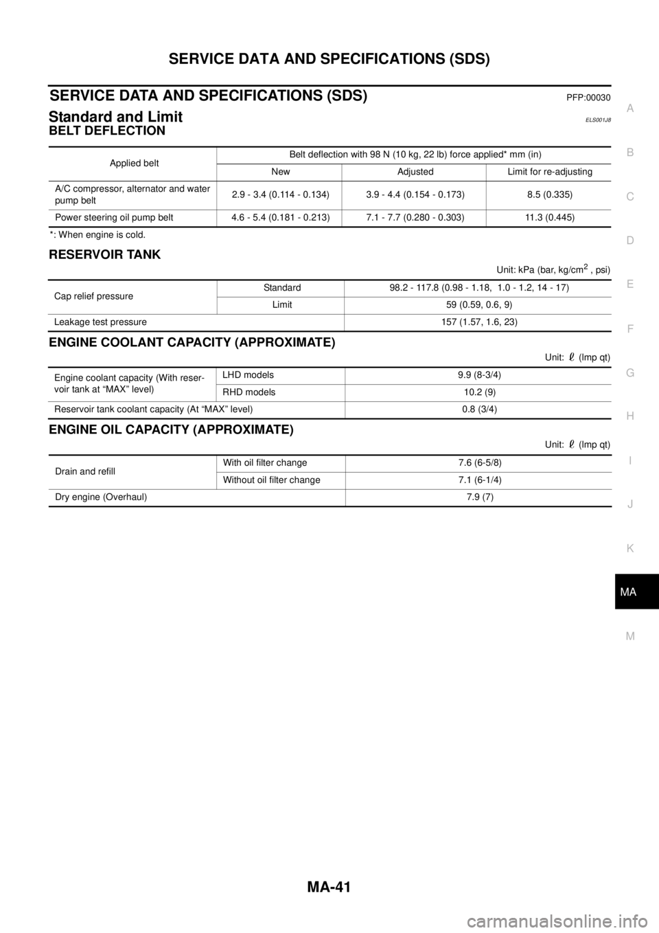
BELT DEFLECTION
*: When engine is cold.
RESERVOIR TANK
Unit:kPa(bar,kg/cm2, psi)
ENGINE COOLANT CAPACITY (APPROXIMATE)
Unit: (lmp qt)
ENGINE OIL CAPACITY (APPROXIMATE)
Unit: (lmp qt) Applied beltBelt deflection with 98 N (10 kg, 22 lb) force applied* mm (in)
New Adjusted Limit for re-adjusting
A/C compressor, alternator and water
pump belt2.9 - 3.4 (0.114 - 0.134) 3.9 - 4.4 (0.154 - 0.173) 8.5 (0.335)
Power steering oil pump belt 4.6 - 5.4 (0.181 - 0.213) 7.1 - 7.7 (0.280 - 0.303) 11.3 (0.445)
Cap relief pressureStandard 98.2 - 117.8 (0.98 - 1.18, 1.0 - 1.2, 14 - 17)
Limit 59 (0.59, 0.6, 9)
Leakage test pressure 157 (1.57, 1.6, 23)
Engine coolant capacity (With reser-
voir tank at “MAX” level)LHD models 9.9 (8-3/4)
RHD models 10.2 (9)
Reservoir tank coolant capacity (At “MAX” level) 0.8 (3/4)
Drain and refillWith oil filter change 7.6 (6-5/8)
Without oil filter change 7.1 (6-1/4)
Dry engine (Overhaul)7.9 (7)
Page 2317 of 3171

MA-42
SERVICE DATA AND SPECIFICATIONS (SDS)
Page 2318 of 3171
MT-1
MANUAL TRANSMISSION
C TRANSMISSION/TRANSAXLE
CONTENTS
D
E
F
G
H
I
J
K
L
M
SECTIONMT
A
B
MT
MANUAL TRANSMISSION
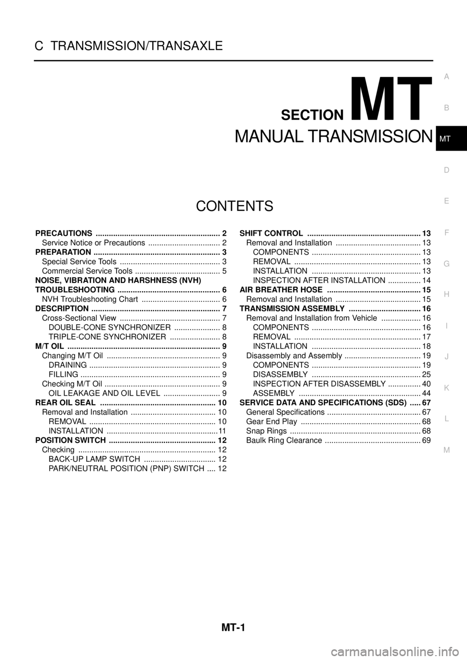
PRECAUTIONS .......................................................... 2
Service Notice or Precautions .................................. 2
PREPARATION ........................................................... 3
Special Service Tools ............................................... 3
Commercial Service Tools ........................................ 5
NOISE, VIBRATION AND HARSHNESS (NVH)
TROUBLESHOOTING ................................................ 6
NVH Troubleshooting Chart ..................................... 6
DESCRIPTION ............................................................ 7
Cross-Sectional View ............................................... 7
DOUBLE-CONE SYNCHRONIZER ...................... 8
TRIPLE-CONE SYNCHRONIZER ........................ 8
M/T OIL ....................................................................... 9
Changing M/T Oil ..................................................... 9
DRAINING ............................................................. 9
FILLING ................................................................. 9
Checking M/T Oil ...................................................... 9
OIL LEAKAGE AND OIL LEVEL ........................... 9
REAR OIL SEAL ...................................................... 10
Removal and Installation ........................................ 10
REMOVAL ........................................................... 10
INSTALLATION .................................................... 11
POSITION SWITCH .................................................. 12
Checking ................................................................ 12
BACK-UP LAMP SWITCH .................................. 12
PARK/NEUTRAL POSITION (PNP) SWITCH ..... 12SHIFT CONTROL ..................................................... 13
Removal and Installation ........................................ 13
COMPONENTS ................................................... 13
REMOVAL ........................................................... 13
INSTALLATION ................................................... 13
INSPECTION AFTER INSTALLATION ................ 14
AIR BREATHER HOSE ............................................ 15
Removal and Installation ........................................ 15
TRANSMISSION ASSEMBLY .................................. 16
Removal and Installation from Vehicle ................... 16
COMPONENTS ................................................... 16
REMOVAL ........................................................... 17
INSTALLATION ................................................... 18
Disassembly and Assembly .................................... 19
COMPONENTS ................................................... 19
DISASSEMBLY ................................................... 25
INSPECTION AFTER DISASSEMBLY ................ 40
ASSEMBLY ......................................................... 44
SERVICE DATA AND SPECIFICATIONS (SDS) ...... 67
General Specifications ............................................ 67
Gear End Play ........................................................ 68
Snap Rings ............................................................. 68
Baulk Ring Clearance ............................................. 69
Page 2319 of 3171

MT-2
PRECAUTIONS
PRECAUTIONS
PFP:00001
ServiceNoticeorPrecautionsECS00ICY
lDo not reuse transmission oil, once it has been drained.
lCheck oil level or replace oil with vehicle on level surface.
lDuring removal or installation, keep inside of transmission clear of dust or dirt.
lCheck for the correct installation status prior to removal or disassembly. If matching mark are required, be
certain they do not interfere with the function of the parts they are applied.
lIn principle, tighten bolts or nuts gradually in several steps working diagonally from inside to outside. If
tightening sequence is specified, use it.
lBe careful not to damage sliding surfaces and mating surfaces.
Page 2320 of 3171
PREPARATION
MT-3
D
E
F
G
H
I
J
K
L
MA
B
MT
PREPARATIONPFP:00002
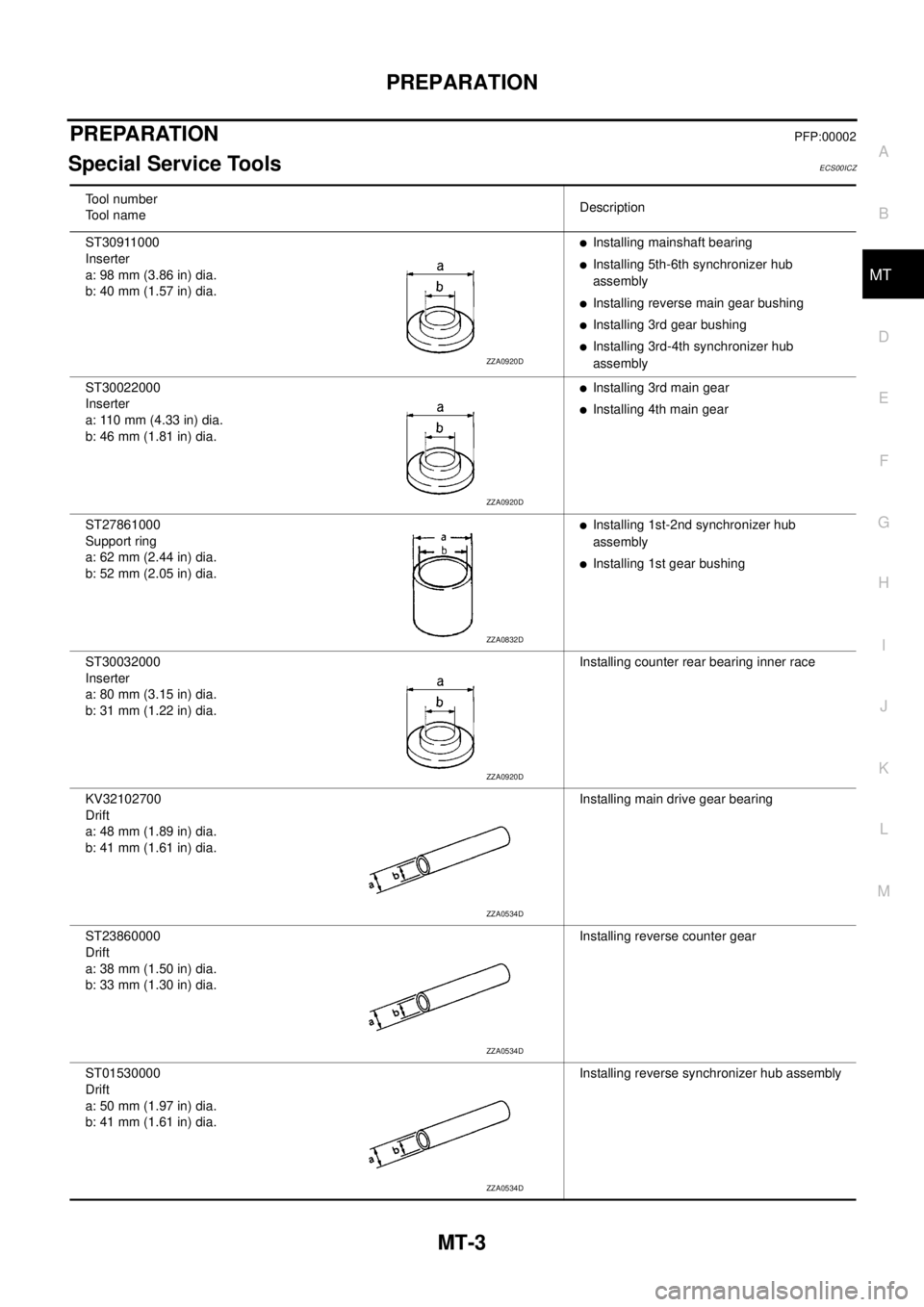
Special Service ToolsECS00ICZ
Tool number
Tool nameDescription
ST30911000
Inserter
a: 98 mm (3.86 in) dia.
b: 40 mm (1.57 in) dia.
lInstalling mainshaft bearing
lInstalling 5th-6th synchronizer hub
assembly
lInstalling reverse main gear bushing
lInstalling 3rd gear bushing
lInstalling 3rd-4th synchronizer hub
assembly
ST30022000
Inserter
a: 110 mm (4.33 in) dia.
b: 46 mm (1.81 in) dia.
lInstalling 3rd main gear
lInstalling 4th main gear
ST27861000
Support ring
a: 62 mm (2.44 in) dia.
b: 52 mm (2.05 in) dia.
lInstalling 1st-2nd synchronizer hub
assembly
lInstalling 1st gear bushing
ST30032000
Inserter
a: 80 mm (3.15 in) dia.
b: 31 mm (1.22 in) dia.Installing counter rear bearing inner race
KV32102700
Drift
a: 48 mm (1.89 in) dia.
b: 41 mm (1.61 in) dia.Installing main drive gear bearing
ST23860000
Drift
a: 38 mm (1.50 in) dia.
b: 33 mm (1.30 in) dia.Installing reverse counter gear
ST01530000
Drift
a: 50 mm (1.97 in) dia.
b: 41 mm (1.61 in) dia.Installing reverse synchronizer hub assembly
ZZA0920D
ZZA0920D
ZZA0832D
ZZA0920D
ZZA0534D
ZZA0534D
ZZA0534D