NISSAN NAVARA 2005 Repair Workshop Manual
NAVARA 2005
NISSAN
NISSAN
https://www.carmanualsonline.info/img/5/57362/w960_57362-0.png
NISSAN NAVARA 2005 Repair Workshop Manual
Trending: fuel injector, jacking, oil viscosity, diagnostic menu, trip computer, display, oil level
Page 2431 of 3171
MTC-44
TROUBLE DIAGNOSIS
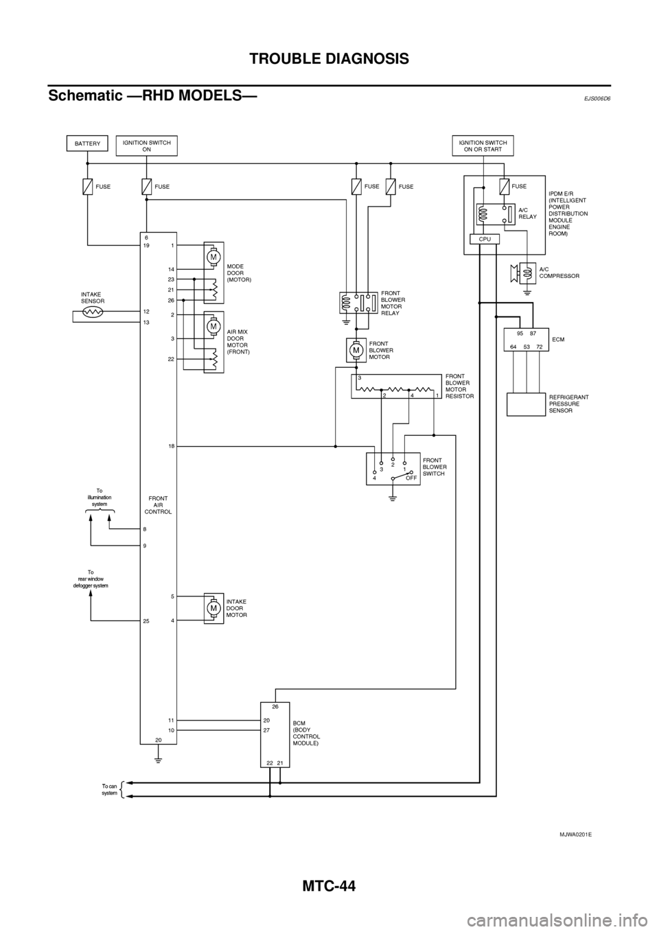
Schematic —RHD MODELS—
EJS006D6
MJWA0201E
Page 2432 of 3171
TROUBLE DIAGNOSIS
MTC-45
C
D
E
F
G
H
I
K
L
MA
B
MTC
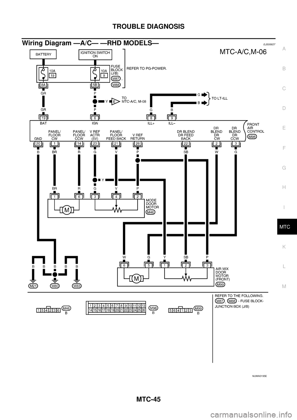
Wiring Diagram —A/C— —RHD MODELS—EJS006D7
MJWA0195E
Page 2433 of 3171
MTC-46
TROUBLE DIAGNOSIS
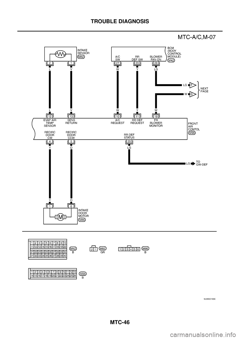
MJWA0196E
Page 2434 of 3171
TROUBLE DIAGNOSIS
MTC-47
C
D
E
F
G
H
I
K
L
MA
B
MTC
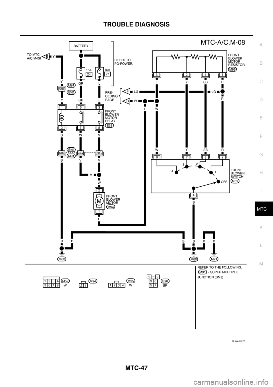
MJWA0197E
Page 2435 of 3171
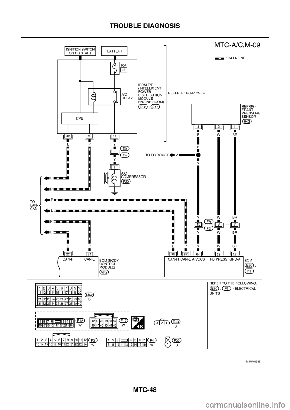
MTC-48
TROUBLE DIAGNOSIS
MJWA0198E
Page 2436 of 3171
TROUBLE DIAGNOSIS
MTC-49
C
D
E
F
G
H
I
K
L
MA
B
MTC
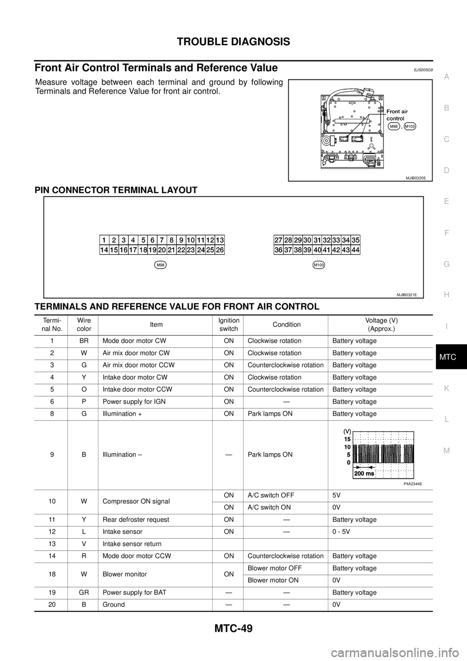
Front Air Control Terminals and Reference ValueEJS005G9
Measure voltage between each terminal and ground by following
Terminals and Reference Value for front air control.
PIN CONNECTOR TERMINAL LAYOUT
TERMINALS AND REFERENCE VALUE FOR FRONT AIR CONTROL
MJIB0320E
MJIB0321E
Te r m i -
nal No.Wire
colorItemIgnition
switchConditionVoltage (V)
(Approx.)
1 BR Mode door motor CW ON Clockwise rotation Battery voltage
2 W Air mix door motor CW ON Clockwise rotation Battery voltage
3 G Air mix door motor CCW ON Counterclockwise rotation Battery voltage
4 Y Intake door motor CW ON Clockwise rotation Battery voltage
5 O Intake door motor CCW ON Counterclockwise rotation Battery voltage
6 P Power supply for IGN ON — Battery voltage
8 G Illumination + ON Park lamps ON Battery voltage
9 B Illumination – — Park lamps ON
10 W Compressor ON signalON A/C switch OFF 5V
ON A/C switch ON 0V
11 Y Rear defroster request ON — Battery voltage
12 L Intake sensor ON — 0 - 5V
13 V Intake sensor return
14 R Mode door motor CCW ON Counterclockwise rotation Battery voltage
18 W Blower monitor ONBlower motor OFF Battery voltage
Blower motor ON 0V
19 GR Power supply for BAT — — Battery voltage
20 B Ground — — 0V
PIIA2344E
Page 2437 of 3171
MTC-50
TROUBLE DIAGNOSIS
21 V Mode door motor feedback ON — 0 - 5V
22 SB Air mix door motor feedback ON — 0 - 5V
23 G Sensor power ON — 5V
25 LG Rear defroster status
26 P Sensor return ON — 0 - 5V
36 PPTC heater relay 1
(LHD models)ONRelay ON Battery voltage
Relay OFF 0V
37 LGPTC heater relay 2
(LHD models)ONRelay ON Battery voltage
Relay OFF 0V
38 BRPTC heater relay 3
(LHD models)ONRelay ON Battery voltage
Relay OFF 0V
39 YSeat heater
(LHD models)ONSeat heater ON Battery voltage
Seat heater OFF 0V
40 RMirror heater
(LHD models)ONMirror heater ON Battery voltage
Mirror heater OFF 0V
41 LCAN-H
(LHD models)ON — 0 - 5V
42 PCAN-L
(LHD models)ON — 0 - 5V Te r m i -
nal No.Wire
colorItemIgnition
switchConditionVoltage (V)
(Approx.)
Page 2438 of 3171
TROUBLE DIAGNOSIS
MTC-51
C
D
E
F
G
H
I
K
L
MA
B
MTC
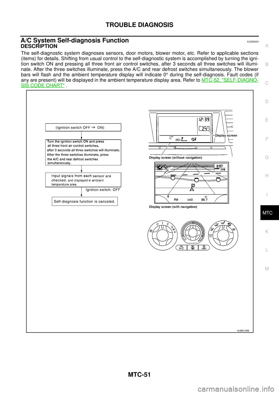
A/C System Self-diagnosis FunctionEJS005GA
DESCRIPTION
The self-diagnostic system diagnoses sensors, door motors, blower motor, etc. Refer to applicable sections
(items) for details. Shifting from usual control to the self-diagnostic system is accomplished by turning the igni-
tion switch ON and pressing all three front air control switches, after 3 seconds all three switches will illumi-
nate. After the three switches illuminate, press the A/C and rear defrost switches simultaneously. The blower
bars will flash and the ambient temperature display will indicate 0°during the self-diagnosis. Fault codes (if
any are present) will be displayed in the ambient temperature display area. Refer toMTC-52, "
SELF-DIAGNO-
SISCODECHART".
MJIB0189E
Page 2439 of 3171

MTC-52
TROUBLE DIAGNOSIS
SELF-DIAGNOSIS CODE CHART
Code No. Reference page
02 EE changed by calibration
04 Mode switch circuit open or shortMTC-58, "
Mode Door Motor Circuit"
05 Blower motor failureMTC-71, "Blower Motor Circuit"
20 BCM not responding to A/C requestMTC-79, "Magnet Clutch Circuit"
21 BCM not responding to rear defroster requestGW-47, "REAR WINDOW DEFOGGER"
22 Air mix door motor (front) circuit failureMTC-63, "Air Mix Door Motor Circuit"
34 Front potentio temperature control (PTC) failure
36 Air mix door motor (front) PBR circuit failureMTC-63, "
Air Mix Door Motor Circuit"
38 Air mix door motor (rear) circuit failureMTC-63, "Air Mix Door Motor Circuit"
56 Intake sensor circuit short
MTC-95, "Intake Sensor Circuit"57 Intake sensor circuit open
62 Defroster door motor circuit failure
80 CAN bus fault
LAN-3, "
Precautions When Using CONSULT-II"81 BCM CAN message missing
82 Intake door motor circuit failureMTC-68, "
Intake Door Motor Circuit"
90 Stuck switch
92 Mode door motor circuit failureMTC-58, "
Mode Door Motor Circuit"
Page 2440 of 3171

TROUBLE DIAGNOSIS
MTC-53
C
D
E
F
G
H
I
K
L
MA
B
MTC
Operational CheckEJS005GB
The purpose of the operational check is to confirm that the system operates properly.
CHECKING BLOWER
1. Turn blower control switch clockwise. Blower should operate on
low speed. The blower symbol should have one blade lit (on dis-
play).
2. Turn the blower control switch again, and continue checking
blower speed and blower symbol until all speeds are checked.
3. Leave blower on MAX speed.
If NG, go to trouble diagnosis procedure for
If OK, continue with next check.
CHECKING DISCHARGE AIR
1. Turn the mode switch.
2. Each position indicator should change shape (on display, if
equipped).
3. Confirm that discharge air comes out according to the air distri-
bution table.
Mode door position is checked in the next step.
If NG, go to trouble diagnosis procedure forMTC-58, "
Mode Door
Motor Circuit".
If OK, continue with next check.
NOTE:
Confirm that the compressor clutch is engaged (sound or visual
inspection) and intake door position is at fresh when the DEF or D/F
is selected.
CHECKING RECIRCULATION
1. Press recirculation ( ) switch one time. Recirculation indica-
tor should illuminate.
2. Press recirculation ( ) switch one more time. Recirculation
indicator should go off.
3. Listen for intake door position change (blower sound should
change slightly).
If NG, go to trouble diagnosis procedure forMTC-68, "
Intake Door
Motor Circuit".
If OK, continue with next check.
NOTE:
Confirm that the compressor clutch is engaged (sound or visual
inspection) and intake door position is at fresh when the DEF or D/F is selected.Conditions : Engine running and at normal operating temperature
MJIB0223E
MJIB0224E
MJIB0284E
MJIB0225E
Trending: fold seats, power windows, air bleeding, fuel fill door release, wheel bolt torque, change wheel, trunk release
