NISSAN NAVARA 2005 Repair Workshop Manual
Manufacturer: NISSAN, Model Year: 2005, Model line: NAVARA, Model: NISSAN NAVARA 2005Pages: 3171, PDF Size: 49.59 MB
Page 2521 of 3171

MTC-134
REFRIGERANT LINES
11. Discharge A/C system using approved refrigerant recovery equipment. Repair the leaking fitting or com-
ponent as necessary.
12. Evacuate and recharge A/C system and perform the leak test to confirm no refrigerant leaks.
13. Perform A/C performance test to ensure system works properly.
Page 2522 of 3171

SERVICE DATA AND SPECIFICATIONS (SDS)
MTC-135
C
D
E
F
G
H
I
K
L
MA
B
MTC
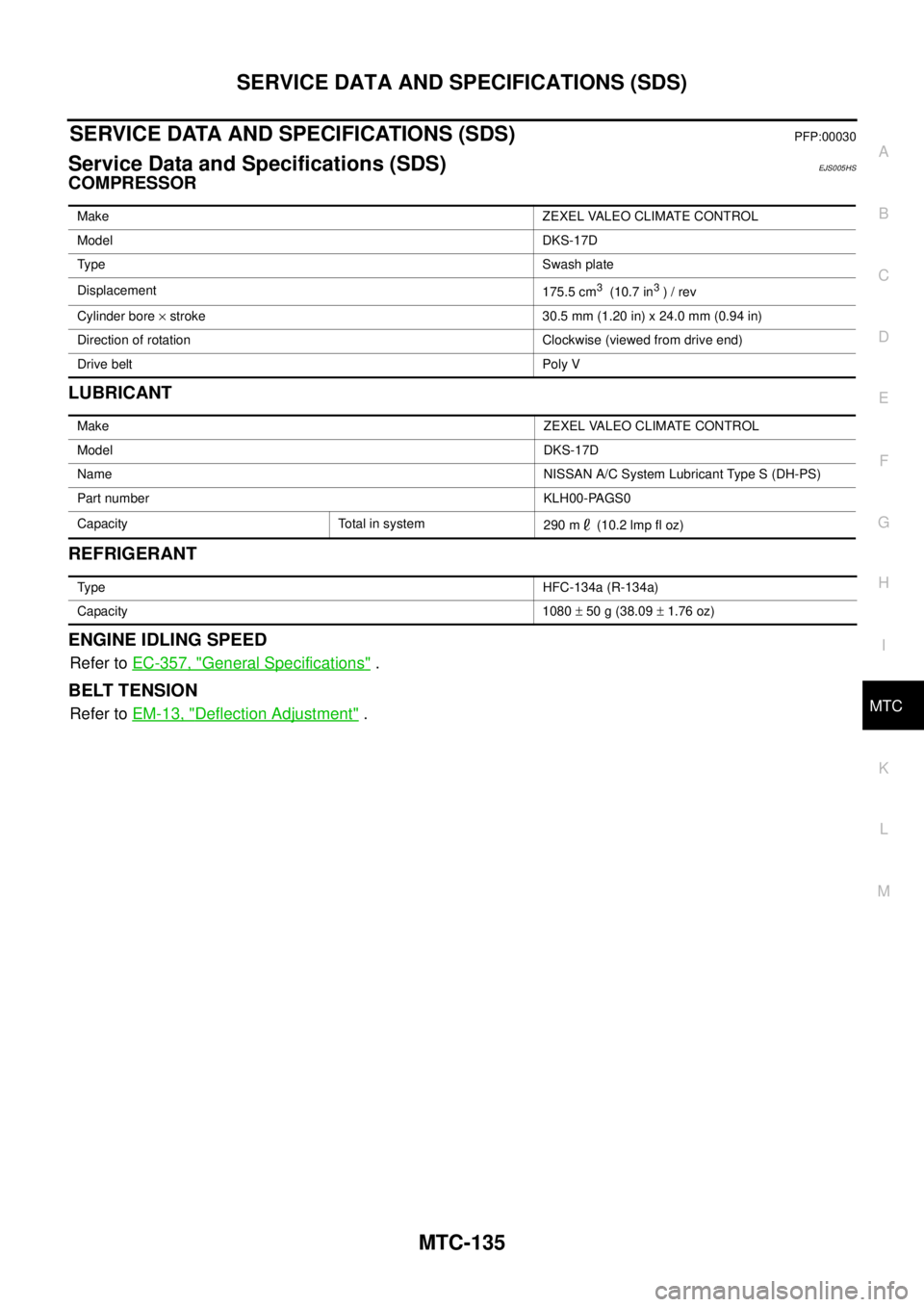
SERVICE DATA AND SPECIFICATIONS (SDS)PFP:00030
Service Data and Specifications (SDS)EJS005HS
COMPRESSOR
LUBRICANT
REFRIGERANT
ENGINE IDLING SPEED
Refer toEC-357, "General Specifications".
BELT TENSION
Refer toEM-13, "Deflection Adjustment".
MakeZEXEL VALEO CLIMATE CONTROL
ModelDKS-17D
Ty p eSwash plate
Displacement
175.5 cm
3(10.7 in3)/rev
Cylinder bore´stroke 30.5 mm (1.20 in) x 24.0 mm (0.94 in)
Direction of rotation Clockwise (viewed from drive end)
Drive belt Poly V
MakeZEXEL VALEO CLIMATE CONTROL
ModelDKS-17D
NameNISSAN A/C System Lubricant Type S (DH-PS)
Part number KLH00-PAGS0
Capacity Total in system
290m (10.2lmpfloz)
Ty p eHFC-134a (R-134a)
Capacity 1080±50g(38.09±1.76 oz)
Page 2523 of 3171

MTC-136
SERVICE DATA AND SPECIFICATIONS (SDS)
Page 2524 of 3171

PB-1
PARKING BRAKE SYSTEM
F BRAKES
CONTENTS
C
D
E
G
H
I
J
K
L
M
SECTIONPB
A
B
PB
PARKING BRAKE SYSTEM
PARKING BRAKE CONTROL ................................... 2
On-Vehicle Service ................................................... 2
INSPECTION ........................................................ 2
COMPONENTS INSPECTION ............................. 2
ADJUSTMENT ...................................................... 2Components ............................................................. 3
Removal and Installation .......................................... 4
REMOVAL ............................................................. 4
INSTALLATION ..................................................... 5
SERVICE DATA AND SPECIFICATIONS (SDS) ........ 6
Parking Brake Control .............................................. 6
Page 2525 of 3171

PB-2
PARKING BRAKE CONTROL
PARKING BRAKE CONTROL
PFP:36010
On-Vehicle ServiceEFS006AJ
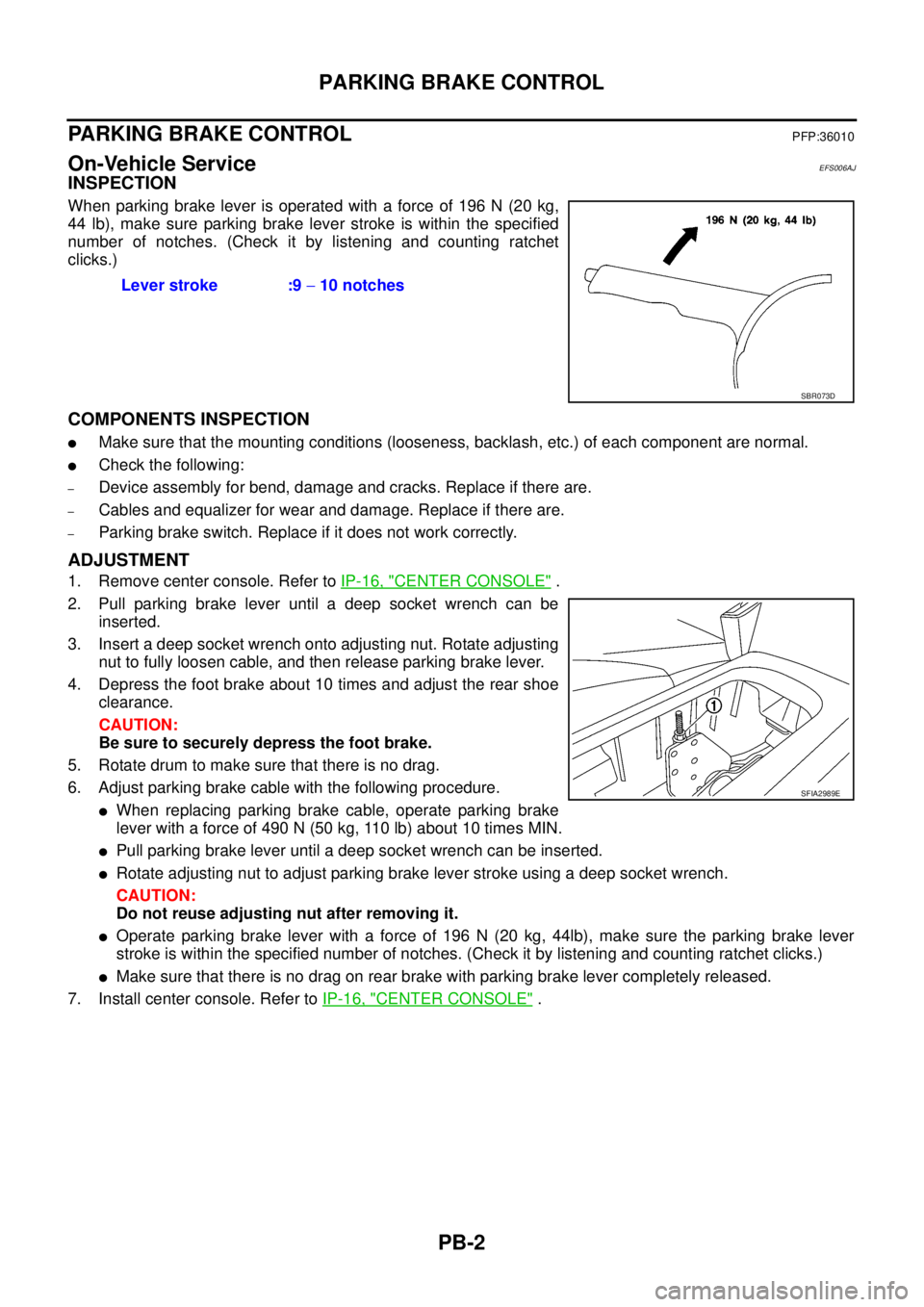
INSPECTION
When parking brake lever is operated with a force of 196 N (20 kg,
44 lb), make sure parking brake lever stroke is within the specified
number of notches. (Check it by listening and counting ratchet
clicks.)
COMPONENTS INSPECTION
lMake sure that the mounting conditions (looseness, backlash, etc.) of each component are normal.
lCheck the following:
–Device assembly for bend, damage and cracks. Replace if there are.
–Cables and equalizer for wear and damage. Replace if there are.
–Parking brake switch. Replace if it does not work correctly.
ADJUSTMENT
1. Remove center console. Refer toIP-16, "CENTER CONSOLE".
2. Pull parking brake lever until a deep socket wrench can be
inserted.
3. Insert a deep socket wrench onto adjusting nut. Rotate adjusting
nut to fully loosen cable, and then release parking brake lever.
4. Depress the foot brake about 10 times and adjust the rear shoe
clearance.
CAUTION:
Be sure to securely depress the foot brake.
5. Rotate drum to make sure that there is no drag.
6. Adjust parking brake cable with the following procedure.
lWhen replacing parking brake cable, operate parking brake
leverwithaforceof490N(50kg,110lb)about10timesMIN.
lPull parking brake lever until a deep socket wrench can be inserted.
lRotate adjusting nut to adjust parking brake lever stroke using a deep socket wrench.
CAUTION:
Do not reuse adjusting nut after removing it.
lOperate parking brake lever with a force of 196 N (20 kg, 44lb), make sure the parking brake lever
stroke is within the specified number of notches. (Check it by listening and counting ratchet clicks.)
lMake sure that there is no drag on rear brake with parking brake lever completely released.
7. Install center console. Refer toIP-16, "
CENTER CONSOLE". Lever stroke :9-10 notches
SBR073D
SFIA2989E
Page 2526 of 3171

PARKING BRAKE CONTROL
PB-3
C
D
E
G
H
I
J
K
L
MA
B
PB
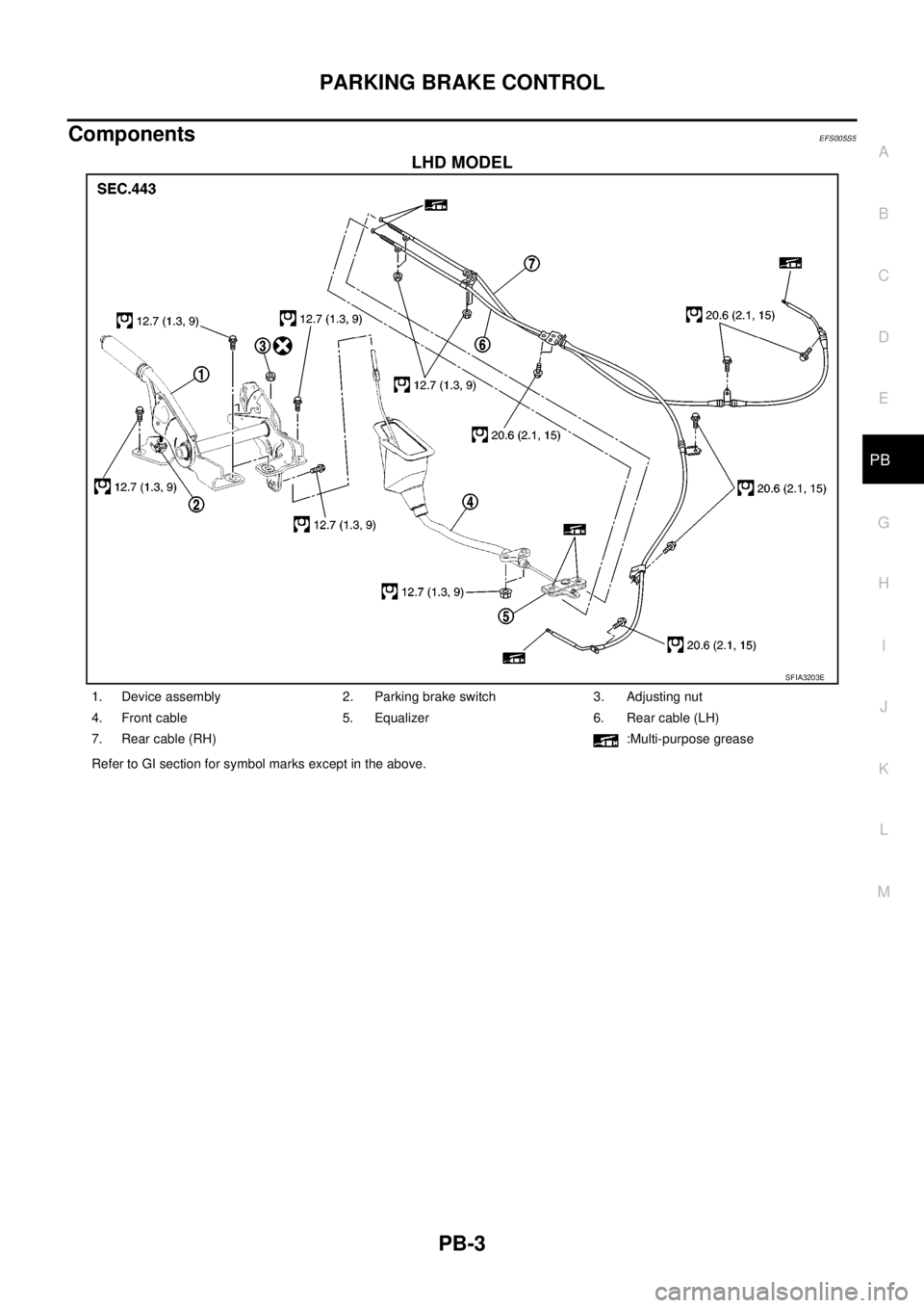
ComponentsEFS005S5
LHD MODEL
SFIA3203E
1. Device assembly 2. Parking brake switch 3. Adjusting nut
4. Front cable 5. Equalizer 6. Rear cable (LH)
7. Rear cable (RH) :Multi-purpose grease
Refer to GI section for symbol marks except in the above.
Page 2527 of 3171

PB-4
PARKING BRAKE CONTROL
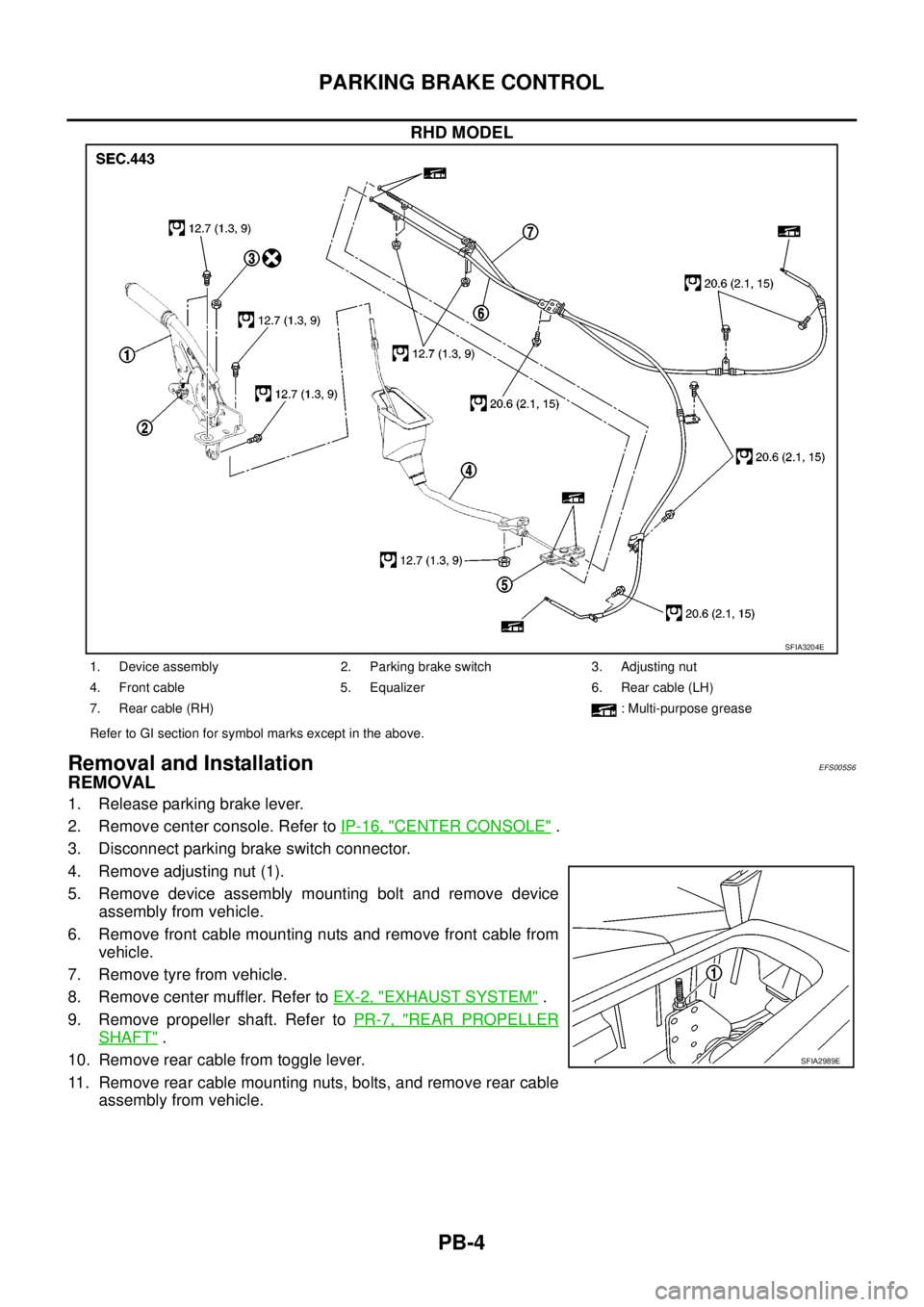
RHD MODEL
Removal and InstallationEFS005S6
REMOVAL
1. Release parking brake lever.
2. Remove center console. Refer toIP-16, "
CENTER CONSOLE".
3. Disconnect parking brake switch connector.
4. Remove adjusting nut (1).
5. Remove device assembly mounting bolt and remove device
assembly from vehicle.
6. Remove front cable mounting nuts and remove front cable from
vehicle.
7. Remove tyre from vehicle.
8. Remove center muffler. Refer toEX-2, "
EXHAUST SYSTEM".
9. Remove propeller shaft. Refer toPR-7, "
REAR PROPELLER
SHAFT".
10. Remove rear cable from toggle lever.
11. Remove rear cable mounting nuts, bolts, and remove rear cable
assembly from vehicle.
SFIA3204E
1. Device assembly 2. Parking brake switch 3. Adjusting nut
4. Front cable 5. Equalizer 6. Rear cable (LH)
7. Rear cable (RH) : Multi-purpose grease
Refer to GI section for symbol marks except in the above.
SFIA2989E
Page 2528 of 3171

PARKING BRAKE CONTROL
PB-5
C
D
E
G
H
I
J
K
L
MA
B
PB
INSTALLATION
1. Installation is in the reverse order of the removal. Refer toPB-3, "Components"for tightening torque.
2. Adjust parking brake. Refer toPB-2, "
ADJUSTMENT".
Page 2529 of 3171

PB-6
SERVICE DATA AND SPECIFICATIONS (SDS)
SERVICE DATA AND SPECIFICATIONS (SDS)
PFP:00030
Parking Brake ControlEFS005SA
Control typeCenter lever
Number of notches [under a force of 196 N (20 kg, 44 lb)] 9 -10 notches
Number of notches when warning lamp switch comes on. 1 notch
Page 2530 of 3171

PG-1
POWER SUPPLY, GROUND & CIRCUIT ELEMENTS
K ELECTRICAL
CONTENTS
C
D
E
F
G
H
I
J
L
M
SECTIONPG
A
B
PG
POWER SUPPLY, GROUND & CIRCUIT ELEMENTS
PRECAUTIONS .......................................................... 3
Precautions for Supplemental Restraint System
(SRS)“AIRBAG”and“SEATBELTPRE-TEN-
SIONER” .................................................................. 3
Wiring Diagrams and Trouble Diagnosis .................. 3
POWER SUPPLY ROUTING CIRCUIT ...................... 4
Schematic ................................................................ 4
Wiring Diagram — POWER — ................................. 5
BATTERY POWER SUPPLY — IGNITION SW.
IN ANY POSITION ................................................ 5
ACCESSORY POWER SUPPLY — IGNITION
SW. IN ACC OR ON ............................................ 10
IGNITION POWER SUPPLY — IGNITION SW.
IN ON ................................................................... 11
IGNITION POWER SUPPLY — IGNITION SW.
IN ON AND/OR START ....................................... 12
IPDM E/R (INTELLIGENT POWER DISTRIBUTION
MODULE ENGINE ROOM) ...................................... 14
System Description ................................................ 14
SYSTEMS CONTROLLED BY IPDM E/R ........... 14
CAN COMMUNICATION LINE CONTROL ......... 14
IPDM E/R STATUS CONTROL ........................... 15
CAN Communication System Description .............. 15
Function of Detecting Ignition Relay Malfunction ... 15
CONSULT-II Function (IPDM E/R) ......................... 16
CONSULT-II BASIC OPERATION ...................... 16
SELF-DIAGNOSTIC RESULTS .......................... 17
DATA MONITOR ................................................. 17
CAN DIAG SUPPORT MNTR ............................. 18
ACTIVE TEST ..................................................... 18
Auto Active Test ..................................................... 19
DESCRIPTION .................................................... 19
OPERATION PROCEDURE ............................... 19
INSPECTION IN AUTO ACTIVE TEST MODE... 20
Schematic .............................................................. 22
IPDM E/R Terminal Arrangement ........................... 23
Check IPDM E/R Power Supply and Ground Circuit... 24Inspection with CONSULT-II (Self-Diagnosis) ........ 25
Removal and Installation of IPDM E/R ................... 26
REMOVAL ........................................................... 26
INSTALLATION ................................................... 26
GROUND CIRCUIT ................................................... 27
Ground Distribution ................................................. 27
MAIN HARNESS ................................................. 27
ENGINE ROOM HARNESS ................................ 30
ENGINE CONTROL HARNESS .......................... 34
BODY HARNESS (LH SIDE) .............................. 35
BODY HARNESS (RH SIDE) .............................. 36
DEFOGGER CABLE ........................................... 37
HARNESS ................................................................. 38
Harness Layout ...................................................... 38
HOW TO READ HARNESS LAYOUT ................. 38
OUTLINE/DOUBLE CAB MODELS .................... 39
OUTLINE/KING CAB MODELS .......................... 40
MAIN HARNESS/LHD MODELS ......................... 41
MAIN HARNESS/RHD MODELS ........................ 44
ENGINE ROOM HARNESS/LHD MODELS ........ 47
ENGINE ROOM HARNESS/RHD MODELS ....... 49
ENGINE CONTROL HARNESS .......................... 51
CHASSIS HARNESS .......................................... 53
BODY HARNESS (LH SIDE)/DOUBLE CAB
MODELS ............................................................. 54
BODY HARNESS (RH SIDE)/DOUBLE CAB
MODELS ............................................................. 56
BODY HARNESS (LH SIDE)/KING CAB MOD-
ELS ...................................................................... 58
BODY HARNESS (RH SIDE)/KING CAB MOD-
ELS ...................................................................... 60
ROOM LAMP HARNESS .................................... 62
FRONT DOOR LH HARNESS/LHD MODELS .... 63
FRONT DOOR RH HARNESS/LHD MODELS ... 63
FRONT DOOR LH HARNESS/RHD MODELS ... 64
FRONT DOOR RH HARNESS/RHD MODELS ... 64
REAR DOOR LH HARNESS/DOUBLE CAB
MODELS ............................................................. 65
REAR DOOR RH HARNESS/DOUBLE CAB
MODELS ............................................................. 65