NISSAN NAVARA 2005 Repair Workshop Manual
NAVARA 2005
NISSAN
NISSAN
https://www.carmanualsonline.info/img/5/57362/w960_57362-0.png
NISSAN NAVARA 2005 Repair Workshop Manual
Trending: heating, warning lights, airbag off, reset sun roof, ABS, EC_main, alternator
Page 2481 of 3171
MTC-94
TROUBLE DIAGNOSIS
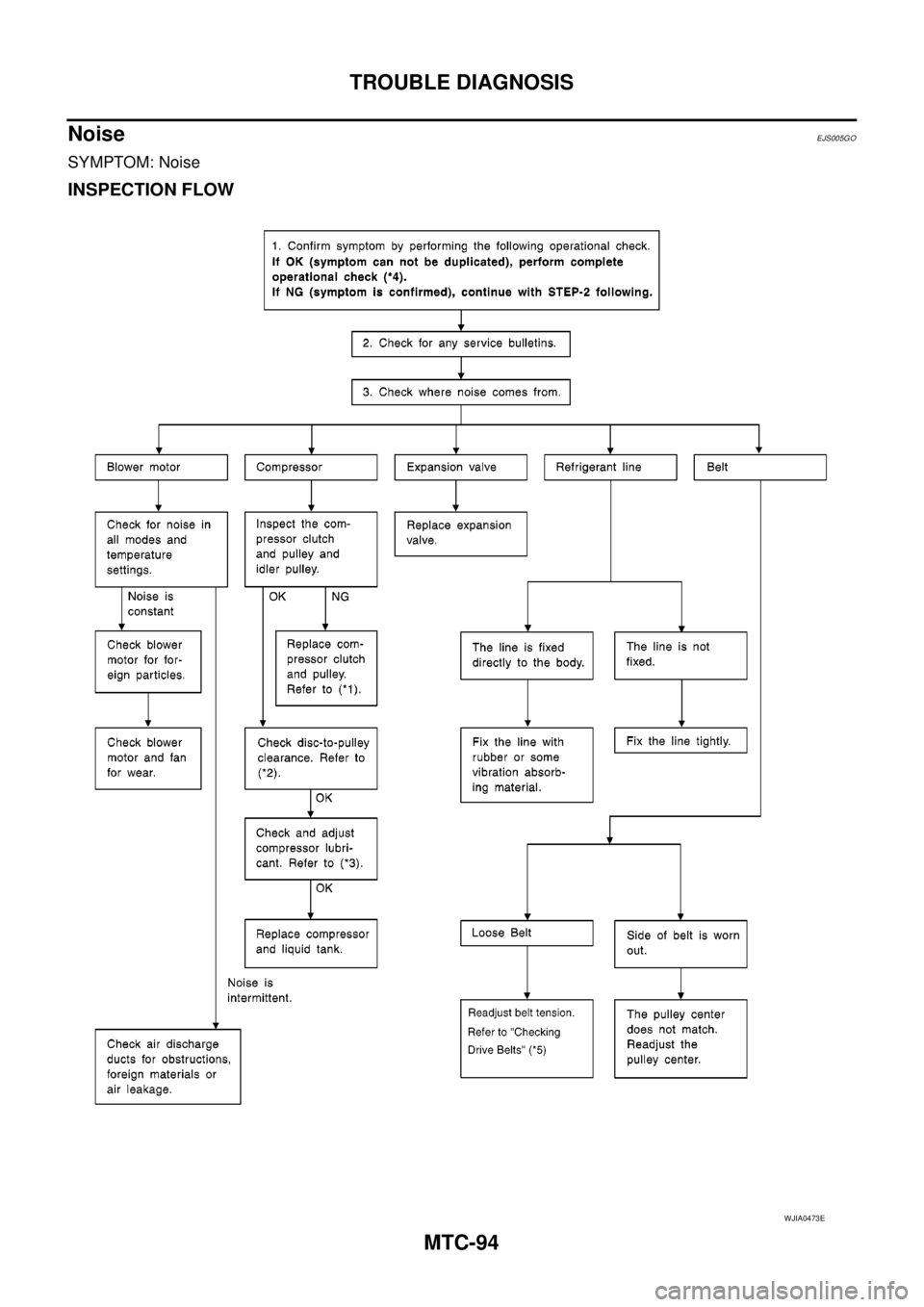
Noise
EJS005GO
SYMPTOM: Noise
INSPECTION FLOW
WJIA0473E
Page 2482 of 3171
TROUBLE DIAGNOSIS
MTC-95
C
D
E
F
G
H
I
K
L
MA
B
MTC
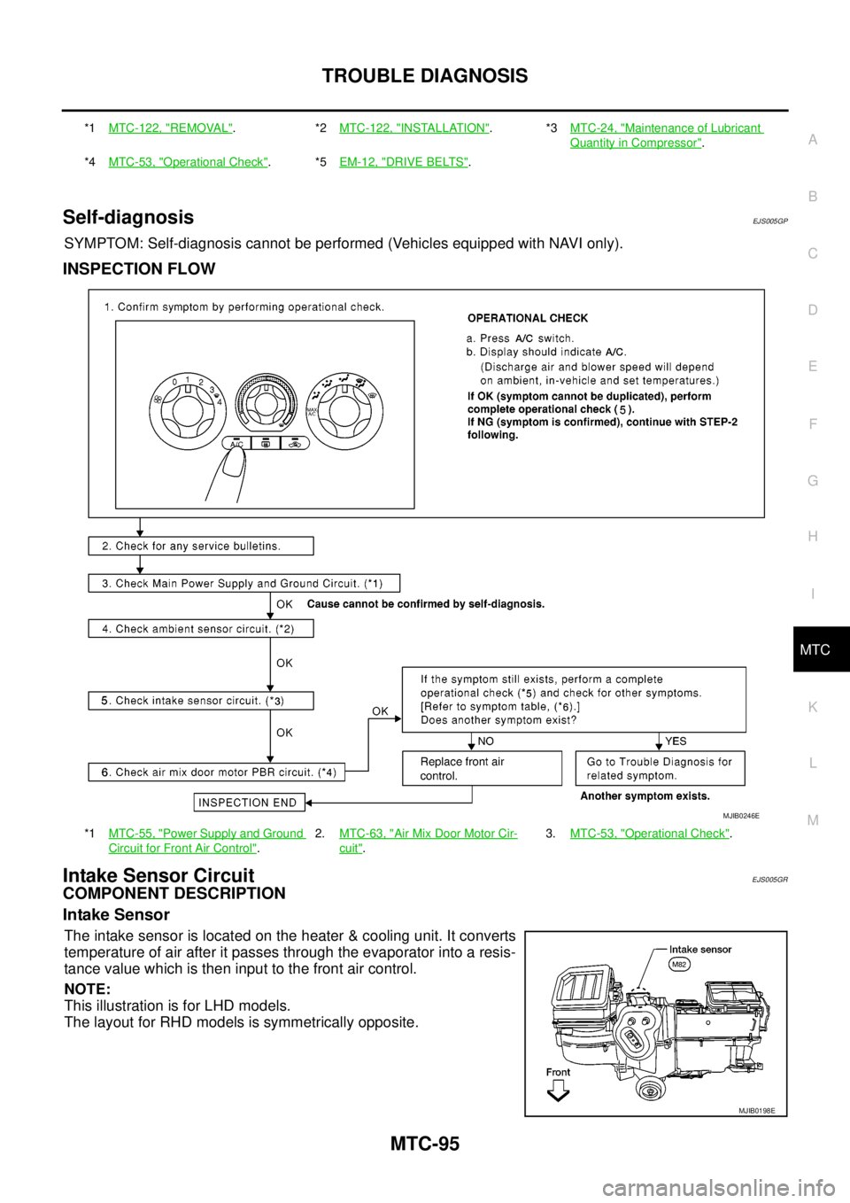
Self-diagnosisEJS005GP
SYMPTOM: Self-diagnosis cannot be performed (Vehicles equipped with NAVI only).
INSPECTION FLOW
Intake Sensor CircuitEJS005GR
COMPONENT DESCRIPTION
Intake Sensor
The intake sensor is located on the heater & cooling unit. It converts
temperature of air after it passes through the evaporator into a resis-
tance value which is then input to the front air control.
NOTE:
This illustration is for LHD models.
The layout for RHD models is symmetrically opposite.
*1MTC-122, "REMOVAL".*2MTC-122, "INSTALLATION".*3MTC-24, "Maintenance of Lubricant
Quantity in Compressor".
*4MTC-53, "
Operational Check".*5EM-12, "DRIVE BELTS".
*1MTC-55, "
Power Supply and Ground
Circuit for Front Air Control".2.MTC-63, "
Air Mix Door Motor Cir-
cuit".3.MTC-53, "
Operational Check".
MJIB0246E
MJIB0198E
Page 2483 of 3171
MTC-96
TROUBLE DIAGNOSIS
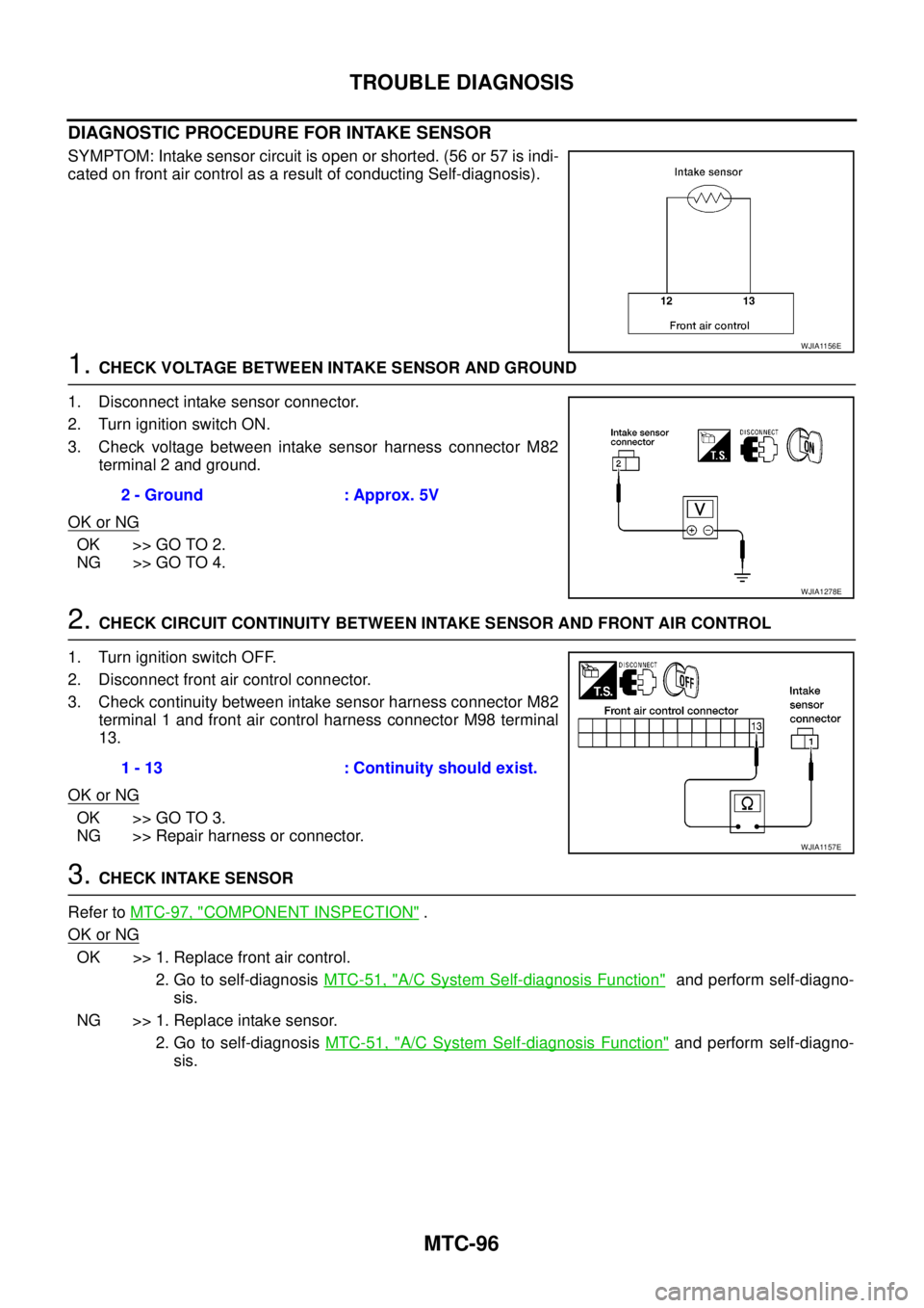
DIAGNOSTIC PROCEDURE FOR INTAKE SENSOR
SYMPTOM: Intake sensor circuit is open or shorted. (56 or 57 is indi-
cated on front air control as a result of conducting Self-diagnosis).
1.CHECK VOLTAGE BETWEEN INTAKE SENSOR AND GROUND
1. Disconnect intake sensor connector.
2. Turn ignition switch ON.
3. Check voltage between intake sensor harness connector M82
terminal 2 and ground.
OK or NG
OK >> GO TO 2.
NG >> GO TO 4.
2.CHECK CIRCUIT CONTINUITY BETWEEN INTAKE SENSOR AND FRONT AIR CONTROL
1. Turn ignition switch OFF.
2. Disconnect front air control connector.
3. Check continuity between intake sensor harness connector M82
terminal 1 and front air control harness connector M98 terminal
13.
OK or NG
OK >> GO TO 3.
NG >> Repair harness or connector.
3.CHECK INTAKE SENSOR
Refer toMTC-97, "
COMPONENT INSPECTION".
OK or NG
OK >> 1. Replace front air control.
2. Go to self-diagnosisMTC-51, "
A/C System Self-diagnosis Function"and perform self-diagno-
sis.
NG >> 1. Replace intake sensor.
2. Go to self-diagnosisMTC-51, "
A/C System Self-diagnosis Function"and perform self-diagno-
sis.
WJIA1156E
2 - Ground : Approx. 5V
WJIA1278E
1 - 13 : Continuity should exist.
WJIA1157E
Page 2484 of 3171
TROUBLE DIAGNOSIS
MTC-97
C
D
E
F
G
H
I
K
L
MA
B
MTC
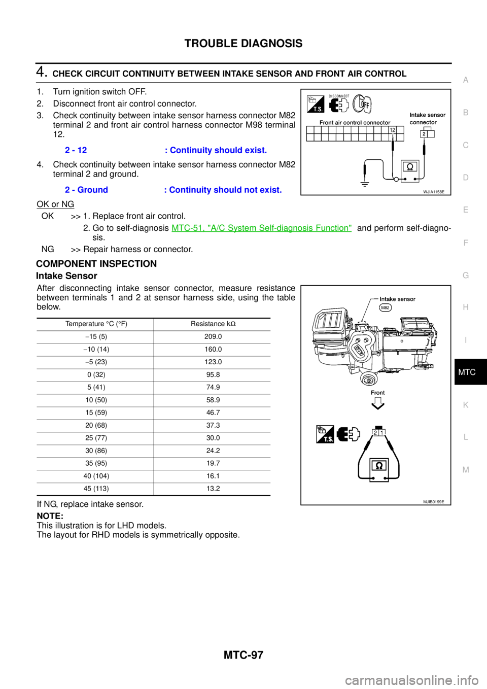
4.CHECK CIRCUIT CONTINUITY BETWEEN INTAKE SENSOR AND FRONT AIR CONTROL
1. Turn ignition switch OFF.
2. Disconnect front air control connector.
3. Check continuity between intake sensor harness connector M82
terminal 2 and front air control harness connector M98 terminal
12.
4. Check continuity between intake sensor harness connector M82
terminal 2 and ground.
OK or NG
OK >> 1. Replace front air control.
2. Go to self-diagnosisMTC-51, "
A/C System Self-diagnosis Function"and perform self-diagno-
sis.
NG >> Repair harness or connector.
COMPONENT INSPECTION
Intake Sensor
After disconnecting intake sensor connector, measure resistance
between terminals 1 and 2 at sensor harness side, using the table
below.
If NG, replace intake sensor.
NOTE:
This illustration is for LHD models.
The layout for RHD models is symmetrically opposite.2 - 12 : Continuity should exist.
2 - Ground : Continuity should not exist.
WJIA1158E
Temperature°C(°F) Resistance kW
-15 (5) 209.0
-10 (14) 160.0
-5 (23) 123.0
0 (32) 95.8
5 (41) 74.9
10 (50) 58.9
15 (59) 46.7
20 (68) 37.3
25 (77) 30.0
30 (86) 24.2
35 (95) 19.7
40 (104) 16.1
45 (113) 13.2
MJIB0199E
Page 2485 of 3171
MTC-98
CONTROL UNIT
CONTROL UNIT
PFP:27500
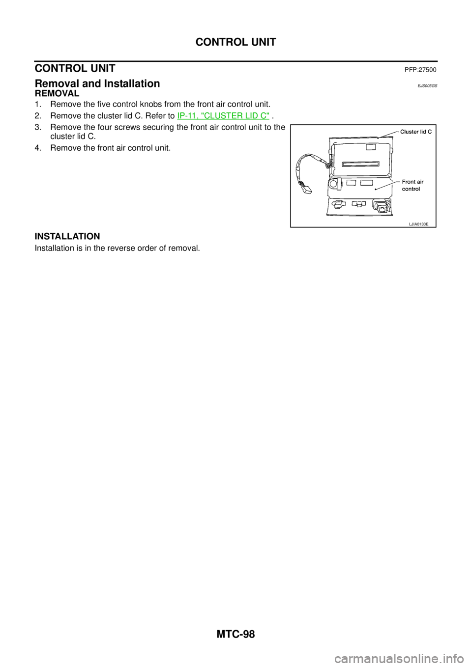
Removal and InstallationEJS005GS
REMOVAL
1. Remove the five control knobs from the front air control unit.
2. Remove the cluster lid C. Refer toIP-11, "
CLUSTER LID C".
3. Remove the four screws securing the front air control unit to the
cluster lid C.
4. Remove the front air control unit.
INSTALLATION
Installation is in the reverse order of removal.
LJIA0130E
Page 2486 of 3171
INTAKE SENSOR
MTC-99
C
D
E
F
G
H
I
K
L
MA
B
MTC
INTAKE SENSORPFP:27723
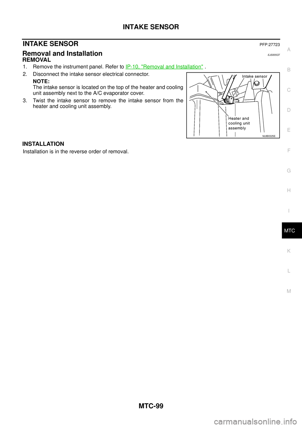
Removal and InstallationEJS005GT
REMOVAL
1. Remove the instrument panel. Refer toIP-10, "Removal and Installation".
2. Disconnect the intake sensor electrical connector.
NOTE:
The intake sensor is located on the top of the heater and cooling
unit assembly next to the A/C evaporator cover.
3. Twist the intake sensor to remove the intake sensor from the
heater and cooling unit assembly.
INSTALLATION
Installation is in the reverse order of removal.
MJIB0325E
Page 2487 of 3171
MTC-100
BLOWER MOTOR
BLOWER MOTOR
PFP:27226
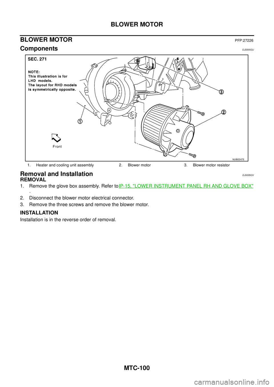
ComponentsEJS005GU
Removal and InstallationEJS005GV
REMOVAL
1. Remove the glove box assembly. Refer toIP-15, "LOWER INSTRUMENT PANEL RH AND GLOVE BOX"
.
2. Disconnect the blower motor electrical connector.
3. Remove the three screws and remove the blower motor.
INSTALLATION
Installation is in the reverse order of removal.
1. Heater and cooling unit assembly 2. Blower motor 3. Blower motor resistor
MJIB0247E
Page 2488 of 3171
AIR CONDITIONER FILTER
MTC-101
C
D
E
F
G
H
I
K
L
MA
B
MTC
AIR CONDITIONER FILTERPFP:27277
Removal and InstallationEJS005GW
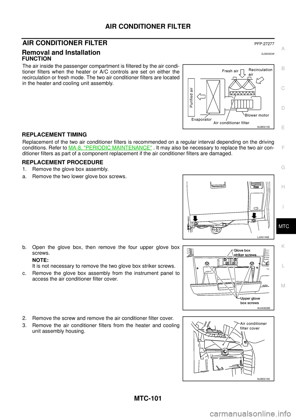
FUNCTION
The air inside the passenger compartment is filtered by the air condi-
tioner filters when the heater or A/C controls are set on either the
recirculation or fresh mode. The two air conditioner filters are located
in the heater and cooling unit assembly.
REPLACEMENT TIMING
Replacement of the two air conditioner filters is recommended on a regular interval depending on the driving
conditions. Refer toMA-8, "
PERIODIC MAINTENANCE". It may also be necessary to replace the two air con-
ditioner filters as part of a component replacement if the air conditioner filters are damaged.
REPLACEMENT PROCEDURE
1. Remove the glove box assembly.
a. Remove the two lower glove box screws.
b. Open the glove box, then remove the four upper glove box
screws.
NOTE:
It is not necessary to remove the two glove box striker screws.
c. Remove the glove box assembly from the instrument panel to
access the air conditioner filter cover.
2. Remove the screw and remove the air conditioner filter cover.
3. Remove the air conditioner filters from the heater and cooling
unit assembly housing.
MJIB0215E
LJIA0146E
WJIA0628E
MJIB0216E
Page 2489 of 3171
MTC-102
AIR CONDITIONER FILTER
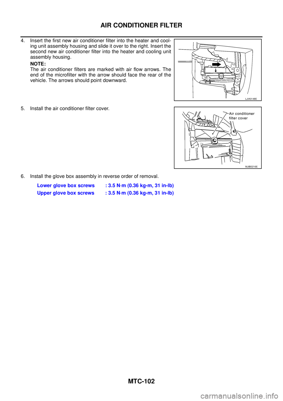
4. Insert the first new air conditioner filter into the heater and cool-
ing unit assembly housing and slide it over to the right. Insert the
second new air conditioner filter into the heater and cooling unit
assembly housing.
NOTE:
The air conditioner filters are marked with air flow arrows. The
end of the microfilter with the arrow should face the rear of the
vehicle. The arrows should point downward.
5. Install the air conditioner filter cover.
6. Install the glove box assembly in reverse order of removal.
LJIA0148E
MJIB0216E
Lower glove box screws : 3.5 N·m (0.36 kg-m, 31 in-lb)
Upper glove box screws : 3.5 N·m (0.36 kg-m, 31 in-lb)
Page 2490 of 3171
HEATER & COOLING UNIT ASSEMBLY
MTC-103
C
D
E
F
G
H
I
K
L
MA
B
MTC
HEATER & COOLING UNIT ASSEMBLYPFP:27110
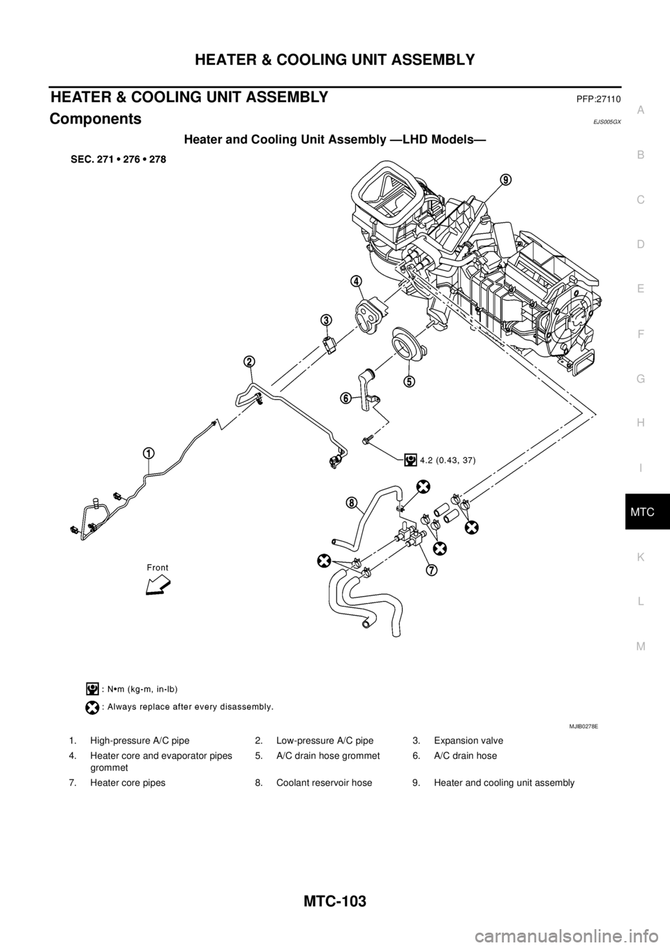
ComponentsEJS005GX
Heater and Cooling Unit Assembly —LHD Models—
MJIB0278E
1. High-pressure A/C pipe 2. Low-pressure A/C pipe 3. Expansion valve
4. Heater core and evaporator pipes
grommet5. A/C drain hose grommet 6. A/C drain hose
7. Heater core pipes 8. Coolant reservoir hose 9. Heater and cooling unit assembly
Trending: oil type, P1272, windshield wipers, wheel size, length, tow bar, navigation system
