NISSAN NAVARA 2005 Repair Workshop Manual
NAVARA 2005
NISSAN
NISSAN
https://www.carmanualsonline.info/img/5/57362/w960_57362-0.png
NISSAN NAVARA 2005 Repair Workshop Manual
Trending: air condition, EC_main, cooling, height adjustment, reset sun roof, radiator, tire size
Page 2501 of 3171
MTC-114
DUCTS AND GRILLES
1. Defroster nozzle 2. LH side demister duct 3. LH ventilator duct
4. RH side demister duct 5. RH ventilator duct 6. Center ventilator duct
7. Heater and cooling unit assembly 8. Floor duct 9. Clips
10. Heat duct
Page 2502 of 3171
DUCTS AND GRILLES
MTC-115
C
D
E
F
G
H
I
K
L
MA
B
MTC
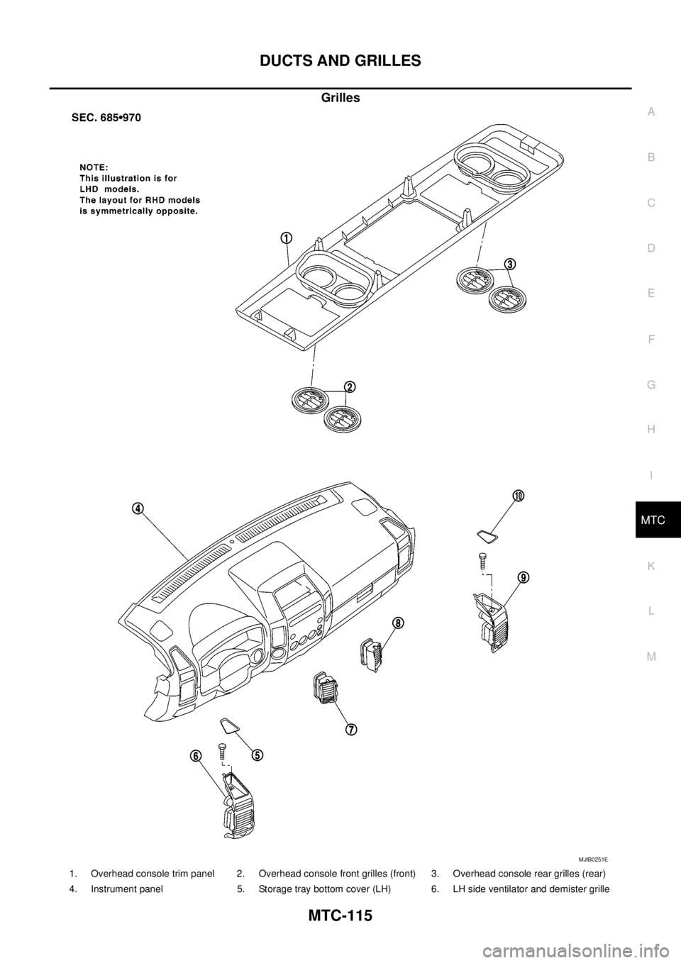
Grilles
MJIB0251E
1. Overhead console trim panel 2. Overhead console front grilles (front) 3. Overhead console rear grilles (rear)
4. Instrument panel 5. Storage tray bottom cover (LH) 6. LH side ventilator and demister grille
Page 2503 of 3171
MTC-116
DUCTS AND GRILLES
Removal and Installation
EJS005H9
CENTER CONSOLE HEAT DUCT AND REAR FINISHER ASSEMBLY GRILLE
Removal
The center console must be removed and disassembled to remove the heat duct and rear finisher assembly
grille. Refer toIP-10, "
Removal and Installation".
Installation
Installation is in the reverse order of removal.
DEFROSTER NOZZLE
Removal
1. Remove the instrument panel trim. Refer toIP-10, "Removal and Installation".
2. Remove the defroster nozzle.
Installation
Installation is in the reverse order of removal.
RH AND LH SIDE DEMISTER DUCT
Removal
1. Remove the instrument panel trim. Refer toIP-10, "Removal and Installation".
2. Remove the RH or LH side demister duct.
Installation
Installation is in the reverse order of removal.
RH AND LH VENTILATOR DUCT
Removal
1. Remove the instrument panel trim. Refer toIP-10, "Removal and Installation".
2. Remove the RH or LH ventilator duct.
Installation
Installation is in the reverse order of removal.
CENTER VENTILATOR DUCT
Removal
1. Remove the instrument panel trim. Refer toIP-10, "Removal and Installation".
2. Remove the defroster nozzle.
3. Remove the RH and LH side demister ducts.
4. Remove the RH and LH ventilator ducts.
5. Remove the center ventilator duct.
Installation
Installation is in the reverse order of removal.
FLOOR DUCT
Removal
1. Remove the floor carpet. Refer toEI-38, "Removal and Installation".
2. Remove the two clips and remove the floor duct.
Installation
Installation is in the reverse order of removal.
GRILLES
Removal
1. Remove the interior trim panel as necessary. Refer toIP-10, "Removal and Installation".
2. Remove the grille from the interior trim panel.
7. LH ventilator grille 8. RH ventilator grille 9. RH side ventilator and demister grille
10. Storage tray bottom cover (RH)
Page 2504 of 3171
DUCTS AND GRILLES
MTC-117
C
D
E
F
G
H
I
K
L
MA
B
MTC
NOTE:
To remove the overhead console front and rear grilles, turn the grille counter-clockwise to release the
grille from the overhead console trim panel.
Installation
Installation is in the reverse order of removal.
Page 2505 of 3171
MTC-118
REFRIGERANT LINES
REFRIGERANT LINES
PFP:92600
HFC-134a (R-134a) Service ProcedureEJS005HA
SETTING OF SERVICE TOOLS AND EQUIPMENT
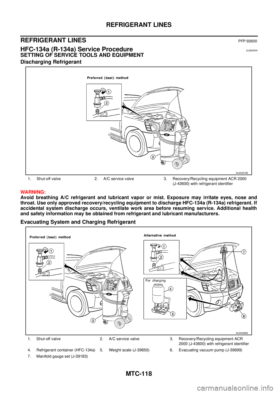
Discharging Refrigerant
WARNING:
Avoid breathing A/C refrigerant and lubricant vapor or mist. Exposure may irritate eyes, nose and
throat. Use only approved recovery/recycling equipment to discharge HFC-134a (R-134a) refrigerant. If
accidental system discharge occurs, ventilate work area before resuming service. Additional health
and safety information may be obtained from refrigerant and lubricant manufacturers.
Evacuating System and Charging Refrigerant
1. Shut-off valve 2. A/C service valve 3. Recovery/Recycling equipment ACR 2000
(J-43600) with refrigerant identifier
WJIA0579E
1. Shut-off valve 2. A/C service valve 3. Recovery/Recycling equipment ACR
2000 (J-43600) with refrigerant identifier
4. Refrigerant container (HFC-134a) 5. Weight scale (J-39650) 6. Evacuating vacuum pump (J-39699)
7. Manifold gauge set (J-39183)
WJIA0580E
Page 2506 of 3171
REFRIGERANT LINES
MTC-119
C
D
E
F
G
H
I
K
L
MA
B
MTC
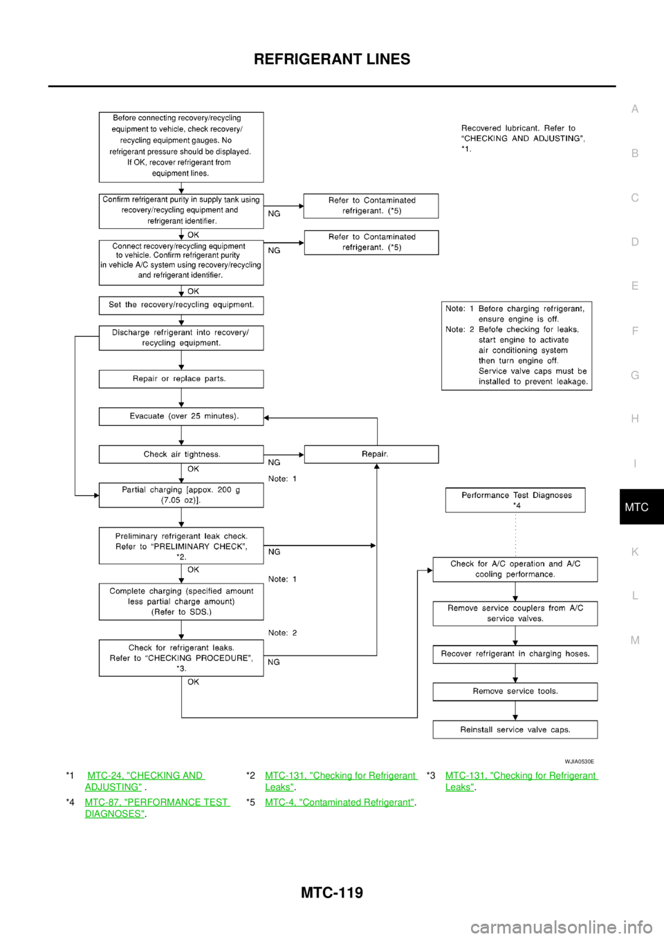
*1MTC-24, "CHECKING AND
ADJUSTING".*2MTC-131, "
Checking for Refrigerant
Leaks".*3MTC-131, "
Checking for Refrigerant
Leaks".
*4MTC-87, "
PERFORMANCE TEST
DIAGNOSES".*5MTC-4, "
Contaminated Refrigerant".
WJIA0530E
Page 2507 of 3171
MTC-120
REFRIGERANT LINES
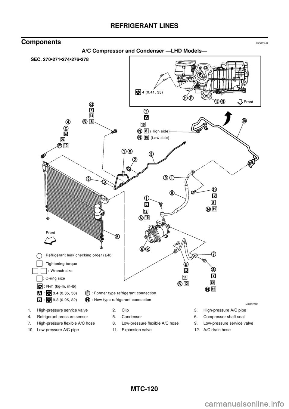
Components
EJS005HB
A/C Compressor and Condenser —LHD Models—
MJIB0276E
1. High-pressure service valve 2. Clip 3. High-pressure A/C pipe
4. Refrigerant pressure sensor 5. Condenser 6. Compressor shaft seal
7. High-pressure flexible A/C hose 8. Low-pressure flexible A/C hose 9. Low-pressure service valve
10. Low-pressure A/C pipe 11. Expansion valve 12. A/C drain hose
Page 2508 of 3171
REFRIGERANT LINES
MTC-121
C
D
E
F
G
H
I
K
L
MA
B
MTC
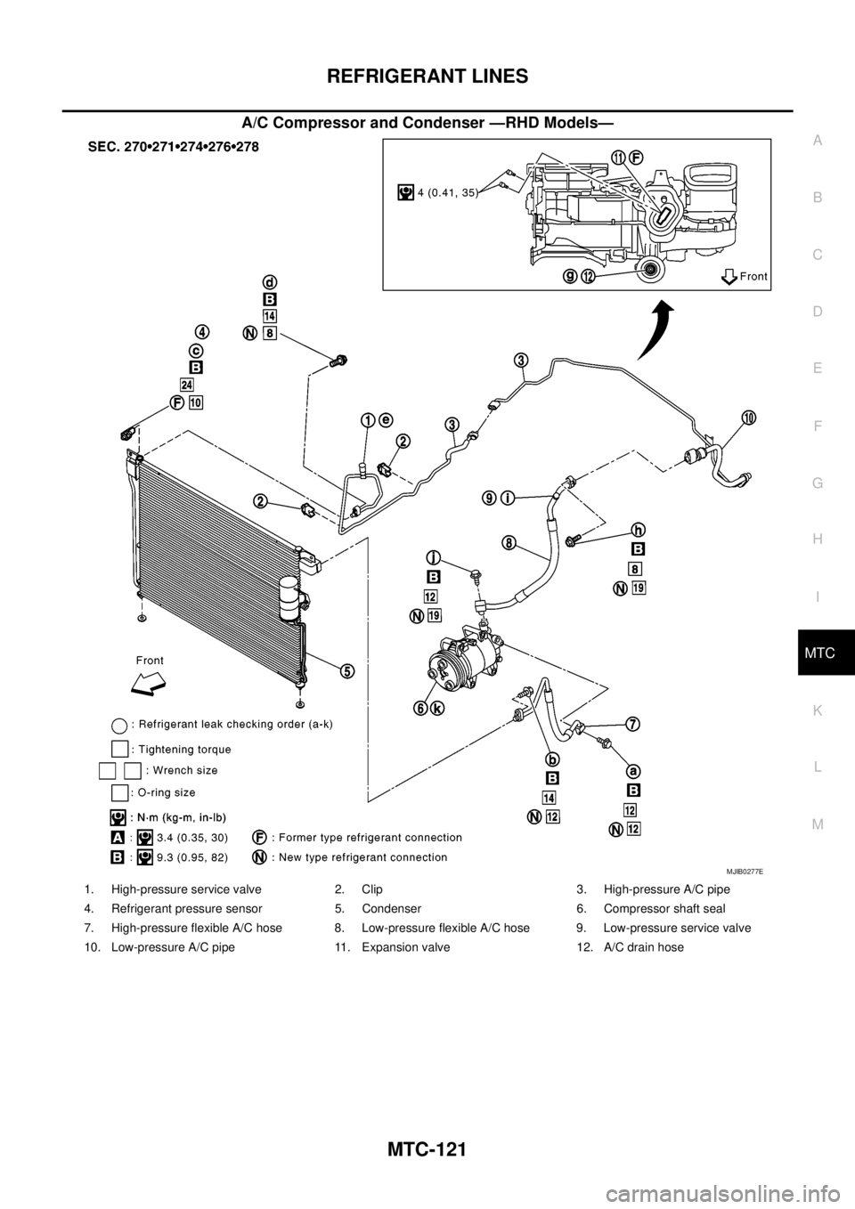
A/C Compressor and Condenser —RHD Models—
MJIB0277E
1. High-pressure service valve 2. Clip 3. High-pressure A/C pipe
4. Refrigerant pressure sensor 5. Condenser 6. Compressor shaft seal
7. High-pressure flexible A/C hose 8. Low-pressure flexible A/C hose 9. Low-pressure service valve
10. Low-pressure A/C pipe 11. Expansion valve 12. A/C drain hose
Page 2509 of 3171
MTC-122
REFRIGERANT LINES
Removal and Installation for Compressor
EJS005HC
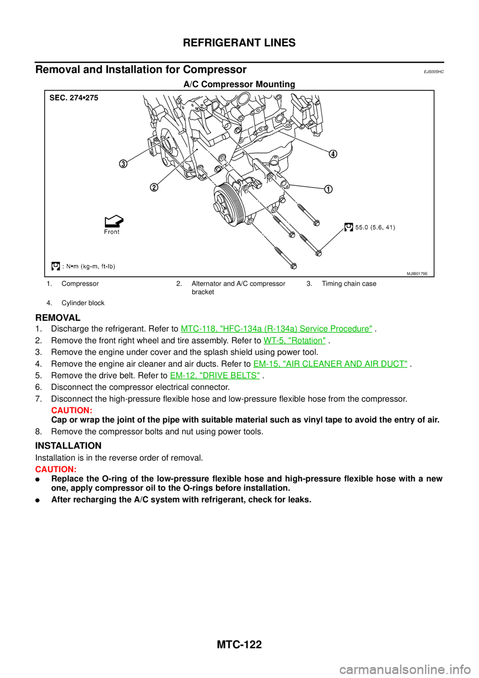
A/C Compressor Mounting
REMOVAL
1. Discharge the refrigerant. Refer toMTC-118, "HFC-134a (R-134a) Service Procedure".
2. Remove the front right wheel and tire assembly. Refer toWT-5, "
Rotation".
3. Remove the engine under cover and the splash shield using power tool.
4. Remove the engine air cleaner and air ducts. Refer toEM-15, "
AIR CLEANER AND AIR DUCT".
5. Remove the drive belt. Refer toEM-12, "
DRIVE BELTS".
6. Disconnect the compressor electrical connector.
7. Disconnect the high-pressure flexible hose and low-pressure flexible hose from the compressor.
CAUTION:
Cap or wrap the joint of the pipe with suitable material such as vinyl tape to avoid the entry of air.
8. Remove the compressor bolts and nut using power tools.
INSTALLATION
Installation is in the reverse order of removal.
CAUTION:
lReplace the O-ring of the low-pressure flexible hose and high-pressure flexible hose with a new
one, apply compressor oil to the O-rings before installation.
lAfter recharging the A/C system with refrigerant, check for leaks.
MJIB0179E
1. Compressor 2. Alternator and A/C compressor
bracket3. Timing chain case
4. Cylinder block
Page 2510 of 3171
REFRIGERANT LINES
MTC-123
C
D
E
F
G
H
I
K
L
MA
B
MTC
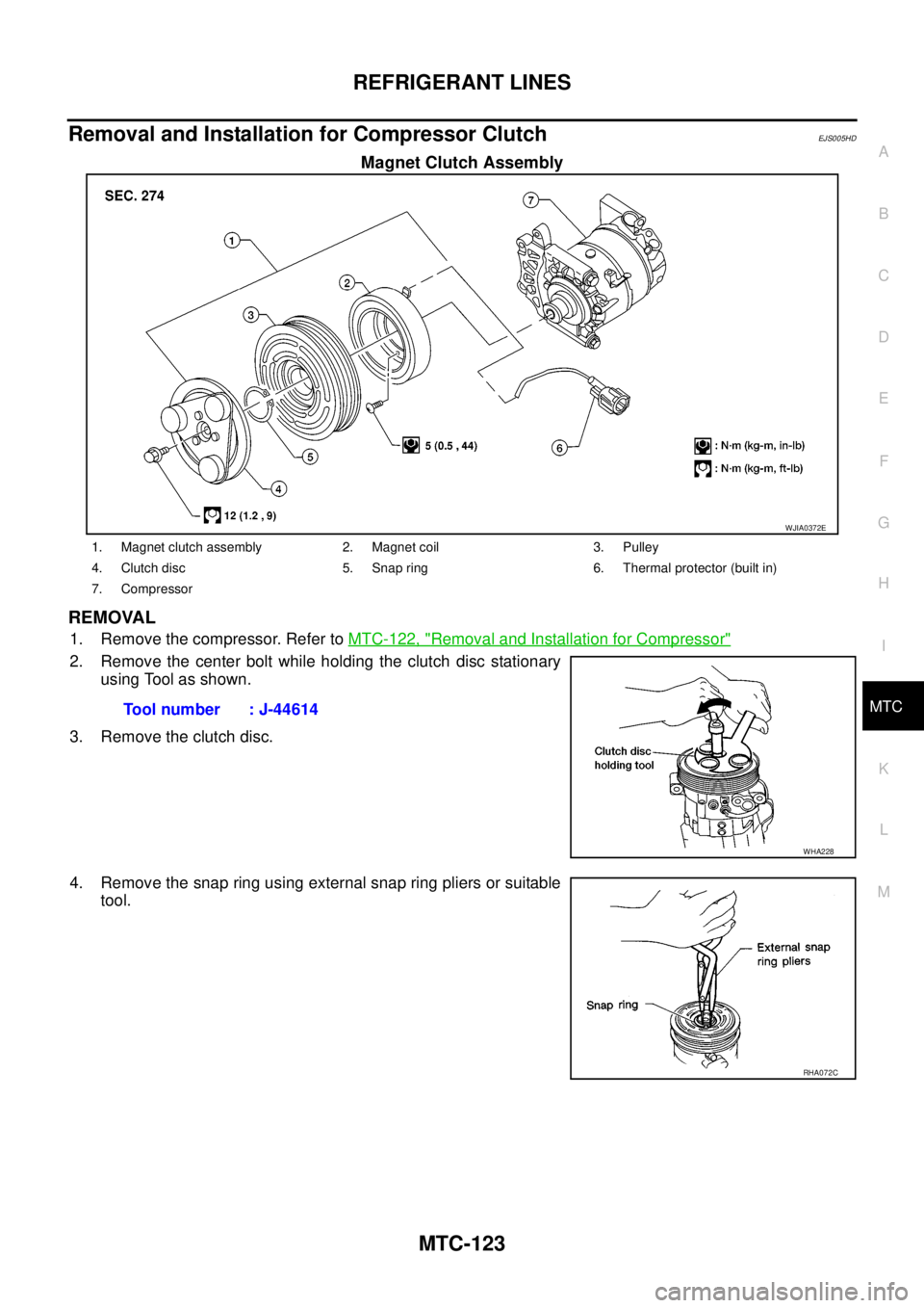
Removal and Installation for Compressor ClutchEJS005HD
Magnet Clutch Assembly
REMOVAL
1. Remove the compressor. Refer toMTC-122, "Removal and Installation for Compressor"
2. Remove the center bolt while holding the clutch disc stationary
using Tool as shown.
3. Remove the clutch disc.
4. Remove the snap ring using external snap ring pliers or suitable
tool.
WJIA0372E
1. Magnet clutch assembly 2. Magnet coil 3. Pulley
4. Clutch disc 5. Snap ring 6. Thermal protector (built in)
7. Compressor
Tool number : J-44614
WHA228
RHA072C
Trending: wheelbase, ignition, traction control, navigation, ECU, battery replacement, rear view mirror

