NISSAN NAVARA 2005 Repair Workshop Manual
Manufacturer: NISSAN, Model Year: 2005, Model line: NAVARA, Model: NISSAN NAVARA 2005Pages: 3171, PDF Size: 49.59 MB
Page 761 of 3171
NATS(NISSAN ANTI-THEFT SYSTEM)
BL-177
C
D
E
F
G
H
J
K
L
MA
B
BL
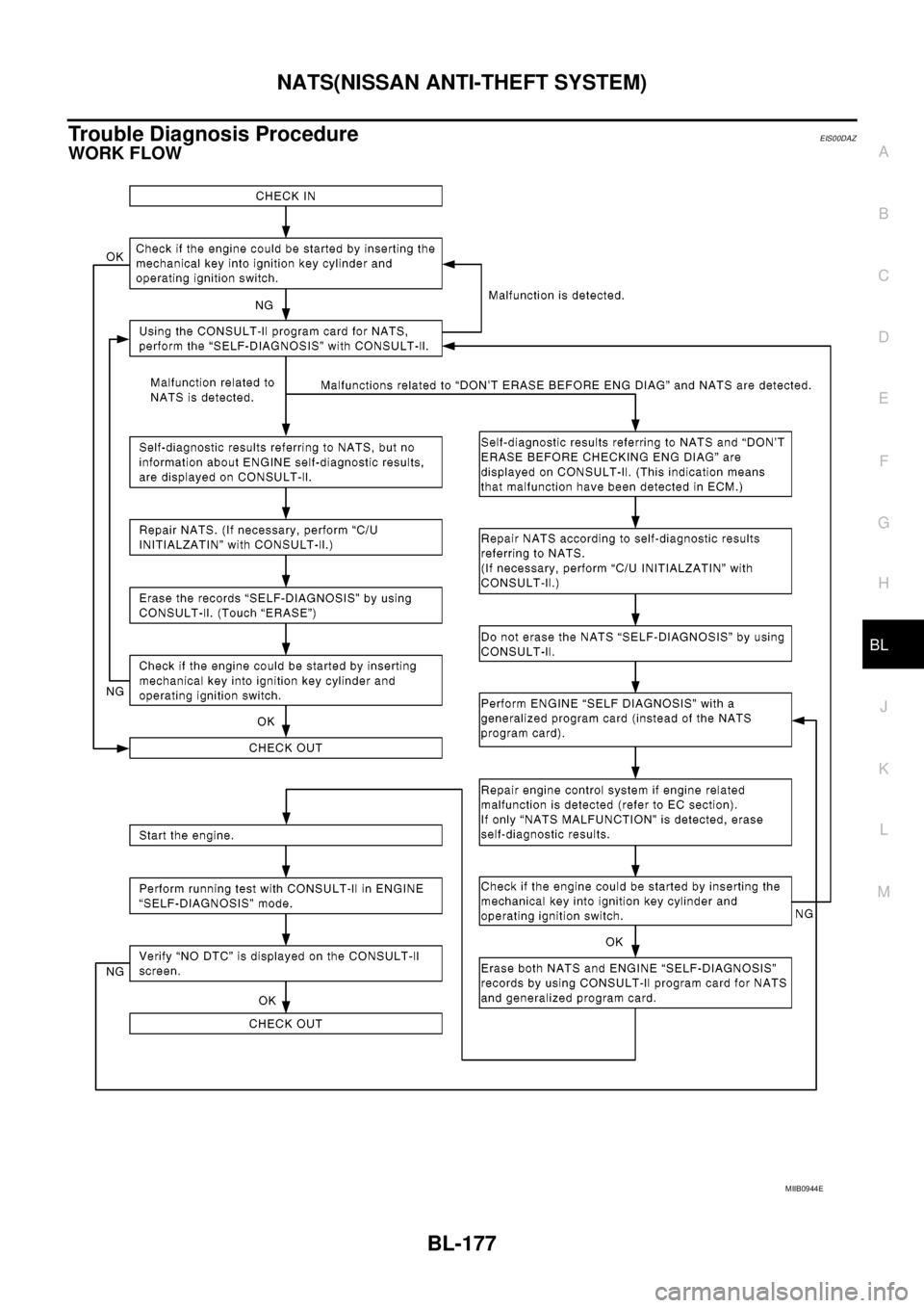
Trouble Diagnosis ProcedureEIS00DAZ
WORK FLOW
MIIB0944E
Page 762 of 3171
BL-178
NATS(NISSAN ANTI-THEFT SYSTEM)
Trouble Diagnoses
EIS00DB0
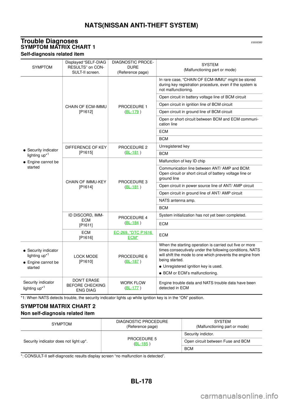
SYMPTOM MATRIX CHART 1
Self-diagnosis related item
*1: When NATS detects trouble, the security indicator lights up while ignition key is in the “ON” position.
SYMPTOM MATRIX CHART 2
Non self-diagnosis related item
*: CONSULT-II self-diagnostic results display screen “no malfunction is detected”.SYMPTOMDisplayed “SELF-DIAG
RESULTS” on CON-
SULT-II screen.DIAGNOSTIC PROCE-
DURE
(Reference page)SYSTEM
(Malfunctioning part or mode)
lSecurity indicator
lighting up*1
lEngine cannot be
startedCHAIN OF ECM-IMMU
[P1612]PROCEDURE 1
(BL-179
)In rare case, “CHAIN OF ECM-IMMU” might be stored
during key registration procedure, even if the system is
not malfunctioning.
Open circuit in battery voltage line of BCM circuit
Open circuit in ignition line of BCM circuit
Open circuit in ground line of BCM circuit
Open or short circuit between BCM and ECM communi-
cation line
ECM
BCM
DIFFERENCE OF KEY
[P1615]PROCEDURE 2
(BL-181
)Unregistered key
BCM
CHAIN OF IMMU-KEY
[P1614]PROCEDURE 3
(BL-181
)Malfunction of key ID chip
Communication line between ANT/ AMP and BCM:
Open circuit or short circuit of battery voltage line or
ground line
Open circuit in power source line of ANT/ AMP circuit
Open circuit in ground line of ANT/ AMP circuit
NATS antenna amp.
BCM
ID DISCORD, IMM-
ECM
[P1611]PROCEDURE 4
(BL-184
)System initialization has not yet been completed.
ECM
ECM
[P1616]EC-269, "
DTC P1616
ECM"ECM
lSecurity indicator
lighting up*1
lEngine cannot be
startedLOCK MODE
[P1610]PROCEDURE 6
(BL-187)When the starting operation is carried out five or more
times consecutively under the following conditions, NATS
will shift the mode to one which prevents the engine from
being started.
lUnregistered ignition key is used.
lBCM or ECM’s malfunctioning.
Security indicator
lighting up*
1
DON'T ERASE
BEFORE CHECKING
ENG DIAGWORK FLOW
(BL-177
)Engine trouble data and NATS trouble data have been
detected in ECM
SYMPTOMDIAGNOSTIC PROCEDURE
(Reference page)SYSTEM
(Malfunctioning part or mode)
Security indicator does not light up*.PROCEDURE 5
(BL-185
)Security indictor.
Open circuit between Fuse and BCM
BCM
Page 763 of 3171
NATS(NISSAN ANTI-THEFT SYSTEM)
BL-179
C
D
E
F
G
H
J
K
L
MA
B
BL
Diagnostic Procedure 1EIS00DB1
Self-diagnostic results:
“CHAIN OF ECM-IMMU” displayed on CONSULT-II screen
First perform the “SELF-DIAG RESULTS” in “BCM” with CONSULT-II, then perform the trouble diagno-
sis of malfunction system indicated “SELF-DIAG RESULTS” of “BCM”. Refer toBCS-16, "
CAN Com-
munication Inspection Using CONSULT-II (Self-Diagnosis)".
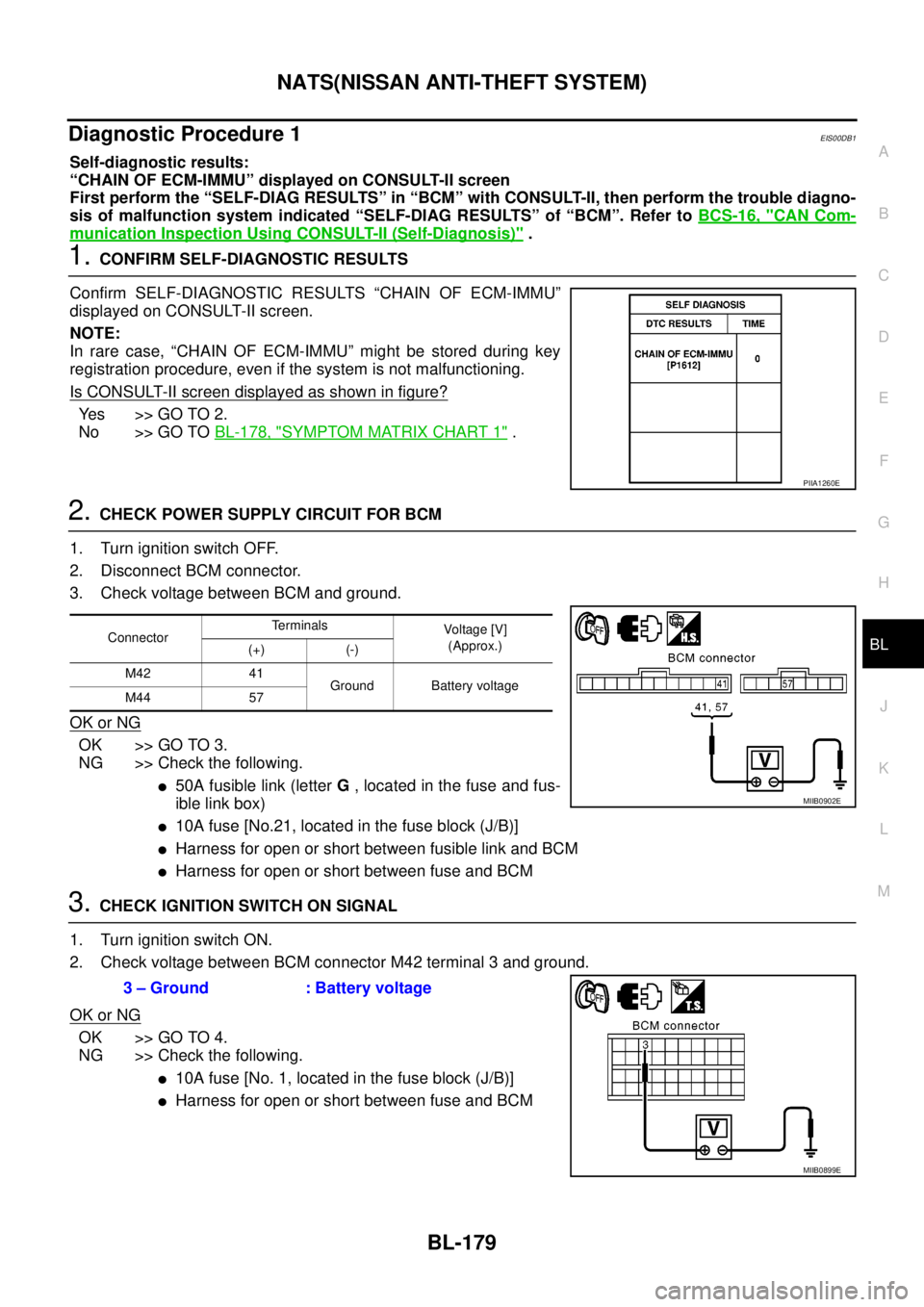
1.CONFIRM SELF-DIAGNOSTIC RESULTS
Confirm SELF-DIAGNOSTIC RESULTS “CHAIN OF ECM-IMMU”
displayed on CONSULT-II screen.
NOTE:
In rare case, “CHAIN OF ECM-IMMU” might be stored during key
registration procedure, even if the system is not malfunctioning.
Is CONSULT-II screen displayed as shown in figure?
Ye s > > G O T O 2 .
No >> GO TOBL-178, "
SYMPTOM MATRIX CHART 1".
2.CHECK POWER SUPPLY CIRCUIT FOR BCM
1. Turn ignition switch OFF.
2. Disconnect BCM connector.
3. Check voltage between BCM and ground.
OK or NG
OK >> GO TO 3.
NG >> Check the following.
l50A fusible link (letterG, located in the fuse and fus-
ible link box)
l10A fuse [No.21, located in the fuse block (J/B)]
lHarness for open or short between fusible link and BCM
lHarness for open or short between fuse and BCM
3.CHECK IGNITION SWITCH ON SIGNAL
1. Turn ignition switch ON.
2. Check voltage between BCM connector M42 terminal 3 and ground.
OK or NG
OK >> GO TO 4.
NG >> Check the following.
l10A fuse [No. 1, located in the fuse block (J/B)]
lHarness for open or short between fuse and BCM
PIIA1260E
ConnectorTerminals
Voltag e [V]
(Approx.)
(+) (-)
M42 41
Ground Battery voltage
M44 57
MIIB0902E
3 – Ground : Battery voltage
MIIB0899E
Page 764 of 3171
BL-180
NATS(NISSAN ANTI-THEFT SYSTEM)
4.CHECK GROUND CIRCUIT FOR BCM
1. Turn ignition switch OFF.
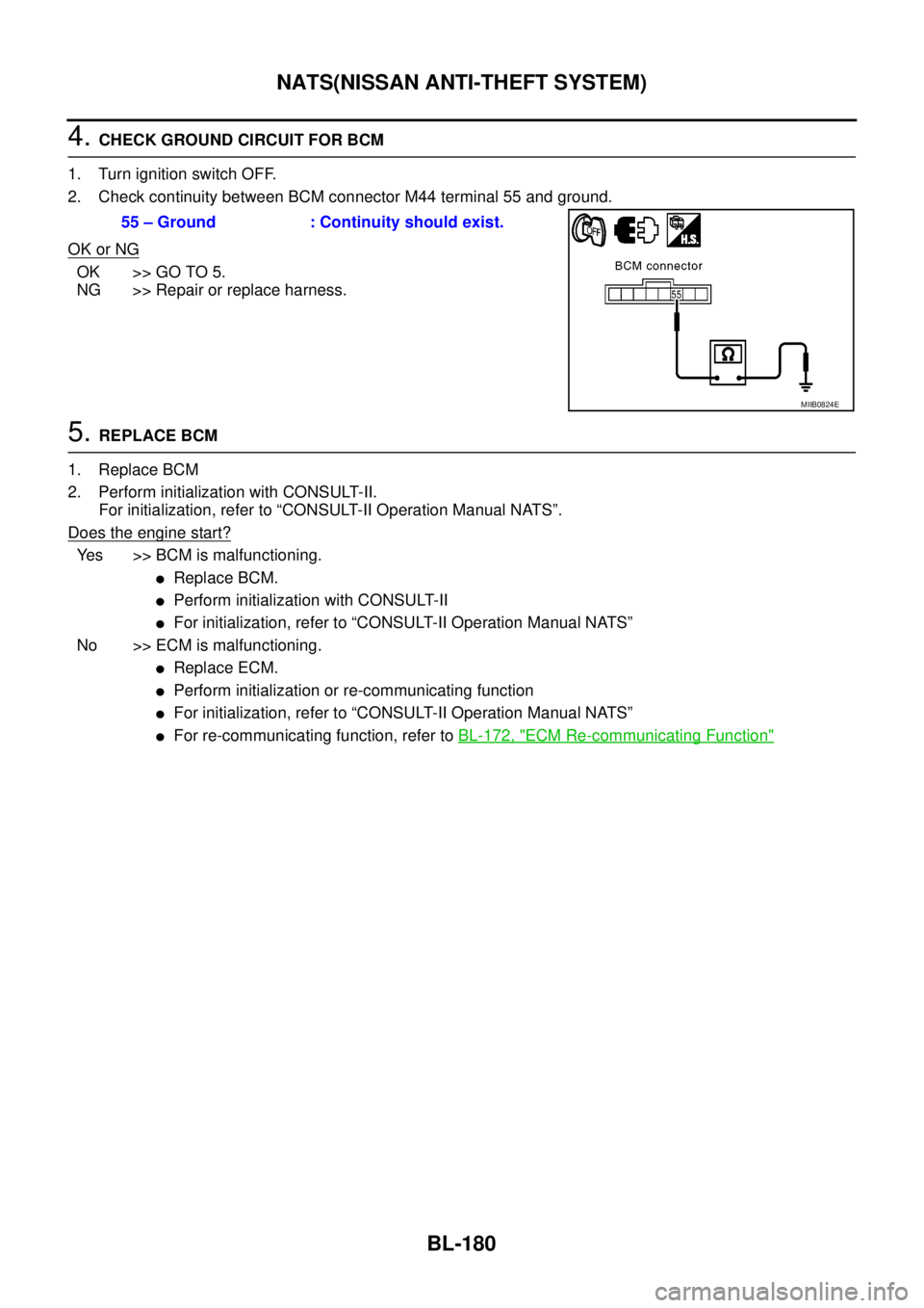
2. Check continuity between BCM connector M44 terminal 55 and ground.
OK or NG
OK >> GO TO 5.
NG >> Repair or replace harness.
5.REPLACE BCM
1. Replace BCM
2. Perform initialization with CONSULT-II.
For initialization, refer to “CONSULT-II Operation Manual NATS”.
Doestheenginestart?
Yes >> BCM is malfunctioning.
lReplace BCM.
lPerform initialization with CONSULT-II
lFor initialization, refer to “CONSULT-II Operation Manual NATS”
No >> ECM is malfunctioning.
lReplace ECM.
lPerform initialization or re-communicating function
lFor initialization, refer to “CONSULT-II Operation Manual NATS”
lFor re-communicating function, refer toBL-172, "ECM Re-communicating Function"
55 – Ground : Continuity should exist.
MIIB0824E
Page 765 of 3171
NATS(NISSAN ANTI-THEFT SYSTEM)
BL-181
C
D
E
F
G
H
J
K
L
MA
B
BL
Diagnostic Procedure 2EIS00DB2
Self-diagnostic results:
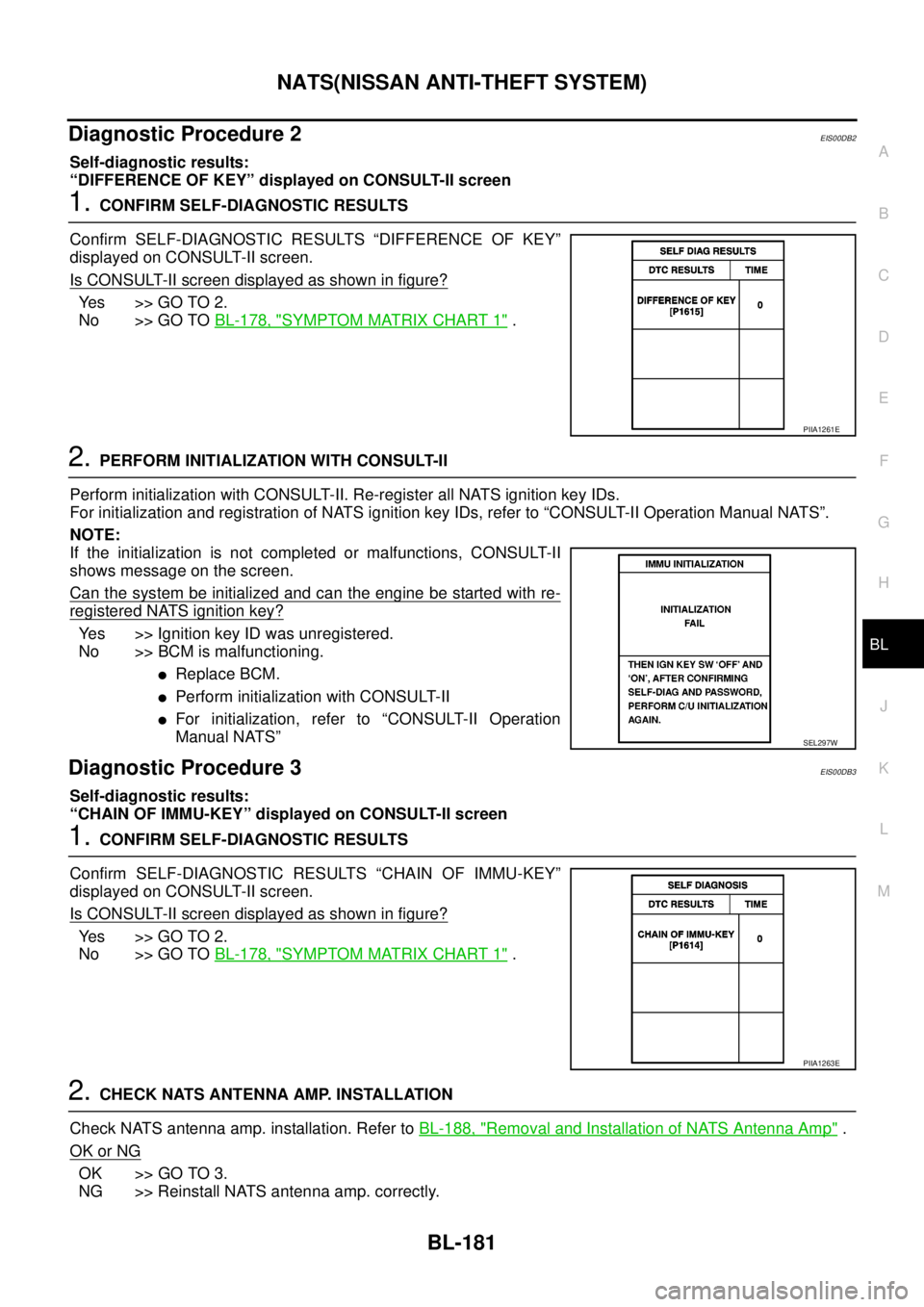
“DIFFERENCE OF KEY” displayed on CONSULT-II screen
1.CONFIRM SELF-DIAGNOSTIC RESULTS
Confirm SELF-DIAGNOSTIC RESULTS “DIFFERENCE OF KEY”
displayed on CONSULT-II screen.
Is CONSULT-II screen displayed as shown in figure?
Ye s > > G O T O 2 .
No >> GO TOBL-178, "
SYMPTOM MATRIX CHART 1".
2.PERFORM INITIALIZATION WITH CONSULT-II
Perform initialization with CONSULT-II. Re-register all NATS ignition key IDs.
For initialization and registration of NATS ignition key IDs, refer to “CONSULT-II Operation Manual NATS”.
NOTE:
If the initialization is not completed or malfunctions, CONSULT-II
shows message on the screen.
Can the system be initialized and can the engine be started with re-
registered NATS ignition key?
Yes >> Ignition key ID was unregistered.
No >> BCM is malfunctioning.
lReplace BCM.
lPerform initialization with CONSULT-II
lFor initialization, refer to “CONSULT-II Operation
Manual NATS”
Diagnostic Procedure 3EIS00DB3
Self-diagnostic results:
“CHAIN OF IMMU-KEY” displayed on CONSULT-II screen
1.CONFIRM SELF-DIAGNOSTIC RESULTS
Confirm SELF-DIAGNOSTIC RESULTS “CHAIN OF IMMU-KEY”
displayed on CONSULT-II screen.
Is CONSULT-II screen displayed as shown in figure?
Ye s > > G O T O 2 .
No >> GO TOBL-178, "
SYMPTOM MATRIX CHART 1".
2.CHECK NATS ANTENNA AMP. INSTALLATION
Check NATS antenna amp. installation. Refer toBL-188, "
Removal and Installation of NATS Antenna Amp".
OK or NG
OK >> GO TO 3.
NG >> Reinstall NATS antenna amp. correctly.
PIIA1261E
SEL297W
PIIA1263E
Page 766 of 3171
BL-182
NATS(NISSAN ANTI-THEFT SYSTEM)
3.CHECK NATS IGNITION KEY ID CHIP
Start engine with another registered NATS ignition key.
Doestheenginestart?
Yes >> Ignition key ID chip is malfunctioning.
lReplace the ignition key
lPerform initialization with CONSULT-II
For initialization, refer to “CONSULT-II Operation Manual NATS”
No >> GO TO 4.
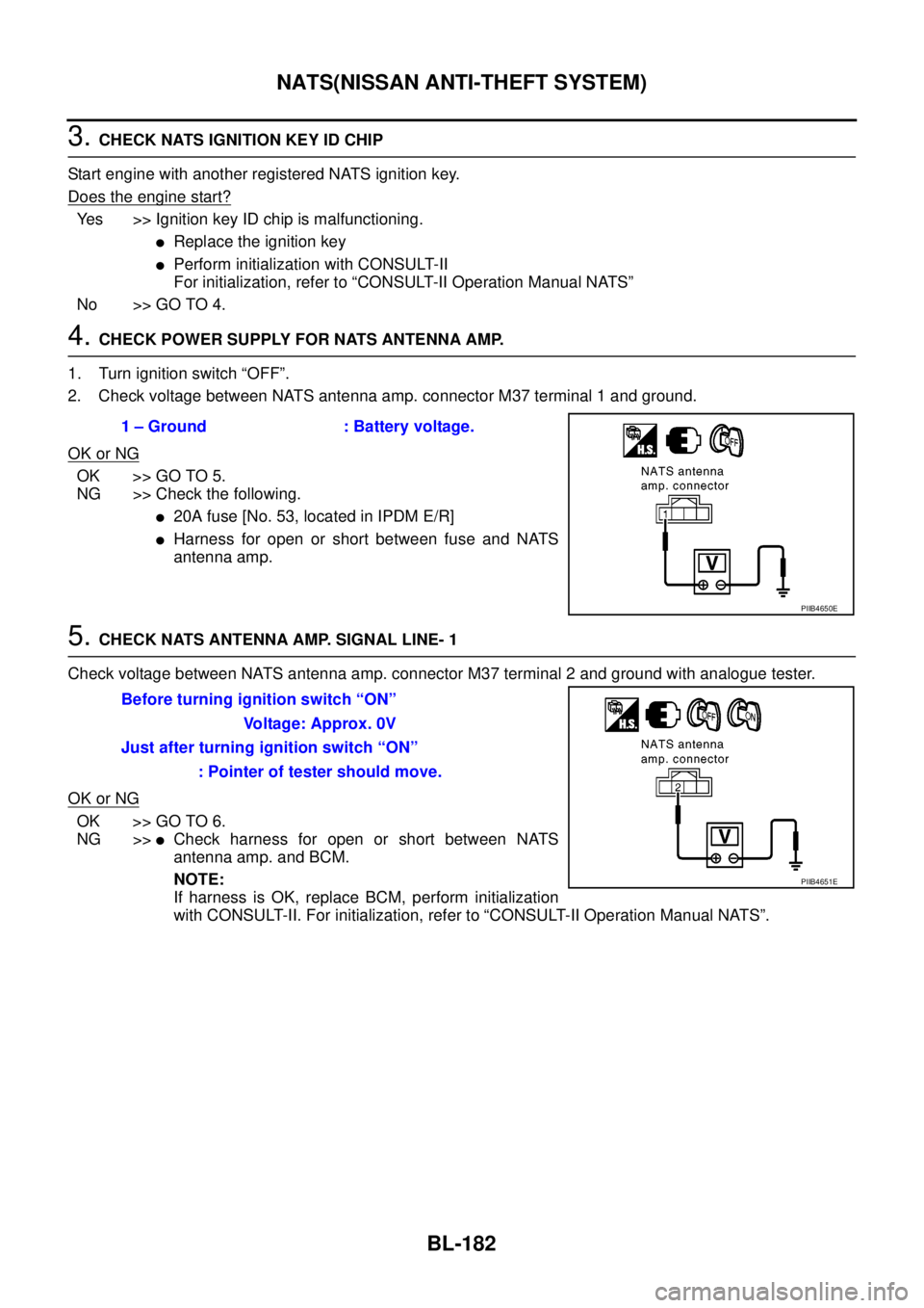
4.CHECK POWER SUPPLY FOR NATS ANTENNA AMP.
1. Turn ignition switch “OFF”.
2. Check voltage between NATS antenna amp. connector M37 terminal 1 and ground.
OK or NG
OK >> GO TO 5.
NG >> Check the following.
l20A fuse [No. 53, located in IPDM E/R]
lHarness for open or short between fuse and NATS
antenna amp.
5.CHECK NATS ANTENNA AMP. SIGNAL LINE- 1
Check voltage between NATS antenna amp. connector M37 terminal 2 and ground with analogue tester.
OK or NG
OK >> GO TO 6.
NG >>
lCheck harness for open or short between NATS
antenna amp. and BCM.
NOTE:
If harness is OK, replace BCM, perform initialization
with CONSULT-II. For initialization, refer to “CONSULT-II Operation Manual NATS”. 1 – Ground : Battery voltage.
PIIB4650E
Before turning ignition switch “ON”
Voltage: Approx. 0V
Just after turning ignition switch “ON”
: Pointer of tester should move.
PIIB4651E
Page 767 of 3171
NATS(NISSAN ANTI-THEFT SYSTEM)
BL-183
C
D
E
F
G
H
J
K
L
MA
B
BL
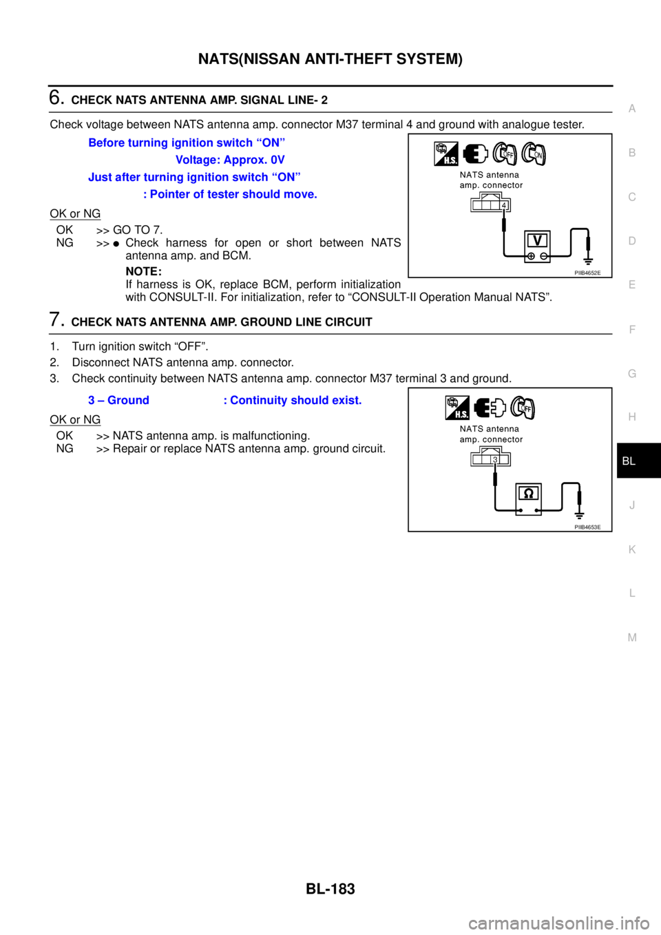
6.CHECK NATS ANTENNA AMP. SIGNAL LINE- 2
Check voltage between NATS antenna amp. connector M37 terminal 4 and ground with analogue tester.
OK or NG
OK >> GO TO 7.
NG >>
lCheck harness for open or short between NATS
antenna amp. and BCM.
NOTE:
If harness is OK, replace BCM, perform initialization
with CONSULT-II. For initialization, refer to “CONSULT-II Operation Manual NATS”.
7.CHECK NATS ANTENNA AMP. GROUND LINE CIRCUIT
1. Turn ignition switch “OFF”.
2. Disconnect NATS antenna amp. connector.
3. Check continuity between NATS antenna amp. connector M37 terminal 3 and ground.
OK or NG
OK >> NATS antenna amp. is malfunctioning.
NG >> Repair or replace NATS antenna amp. ground circuit.Before turning ignition switch “ON”
Voltage: Approx. 0V
Just after turning ignition switch “ON”
: Pointer of tester should move.
PIIB4652E
3 – Ground : Continuity should exist.
PIIB4653E
Page 768 of 3171
BL-184
NATS(NISSAN ANTI-THEFT SYSTEM)
Diagnostic Procedure 4
EIS00DB4
Self-diagnostic results:
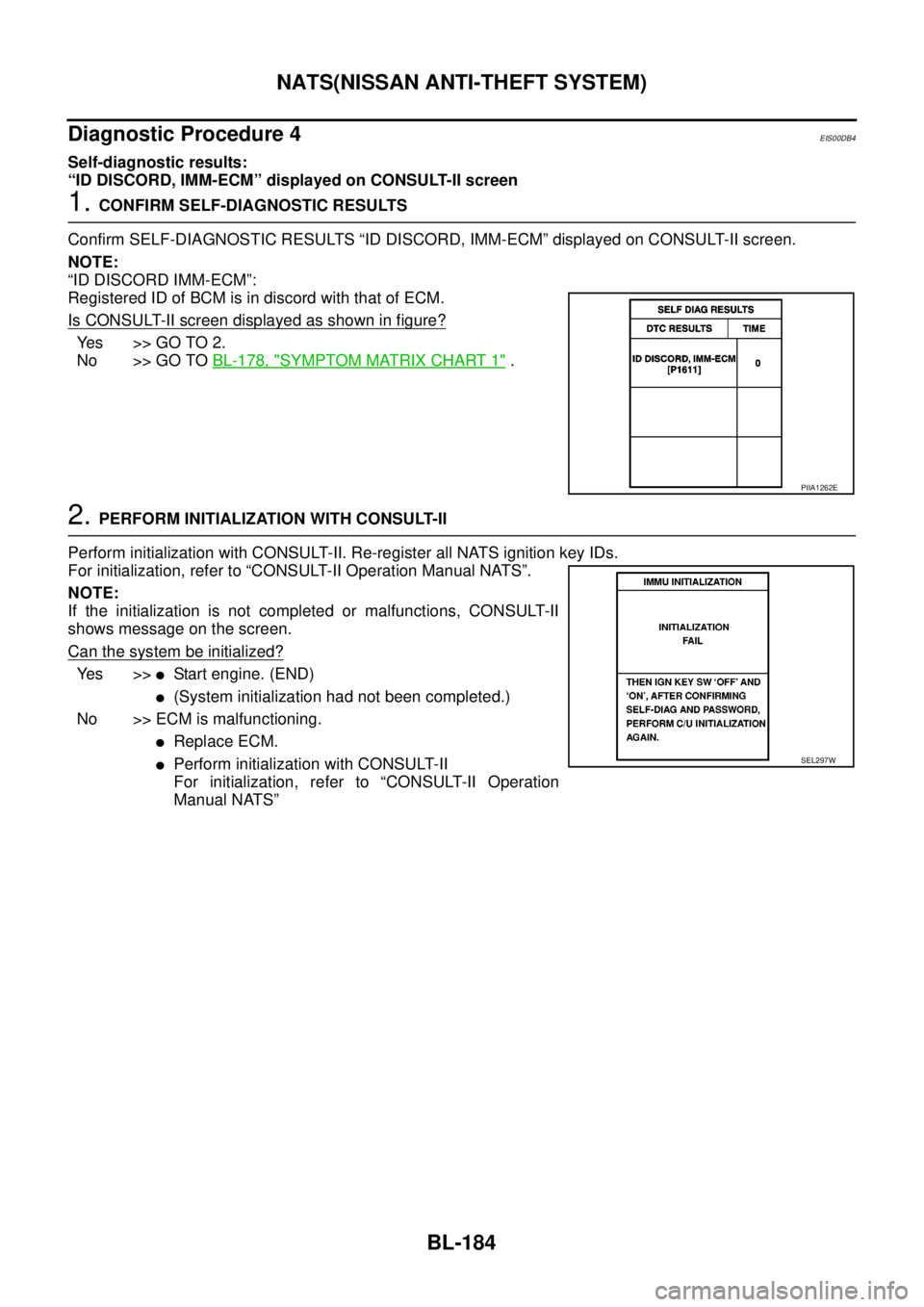
“ID DISCORD, IMM-ECM” displayed on CONSULT-II screen
1.CONFIRM SELF-DIAGNOSTIC RESULTS
Confirm SELF-DIAGNOSTIC RESULTS “ID DISCORD, IMM-ECM” displayed on CONSULT-II screen.
NOTE:
“ID DISCORD IMM-ECM”:
Registered ID of BCM is in discord with that of ECM.
Is CONSULT-II screen displayed as shown in figure?
Yes >>GOTO2.
No >> GO TOBL-178, "
SYMPTOM MATRIX CHART 1".
2.PERFORM INITIALIZATION WITH CONSULT-II
Perform initialization with CONSULT-II. Re-register all NATS ignition key IDs.
For initialization, refer to “CONSULT-II Operation Manual NATS”.
NOTE:
If the initialization is not completed or malfunctions, CONSULT-II
shows message on the screen.
Can the system be initialized?
Ye s > >lStart engine. (END)
l(System initialization had not been completed.)
No >> ECM is malfunctioning.
lReplace ECM.
lPerform initialization with CONSULT-II
For initialization, refer to “CONSULT-II Operation
Manual NATS”
PIIA1262E
SEL297W
Page 769 of 3171
NATS(NISSAN ANTI-THEFT SYSTEM)
BL-185
C
D
E
F
G
H
J
K
L
MA
B
BL
Diagnostic Procedure 5EIS00DB5
“SECURITY INDICATOR LAMP DOES NOT LIGHT UP”
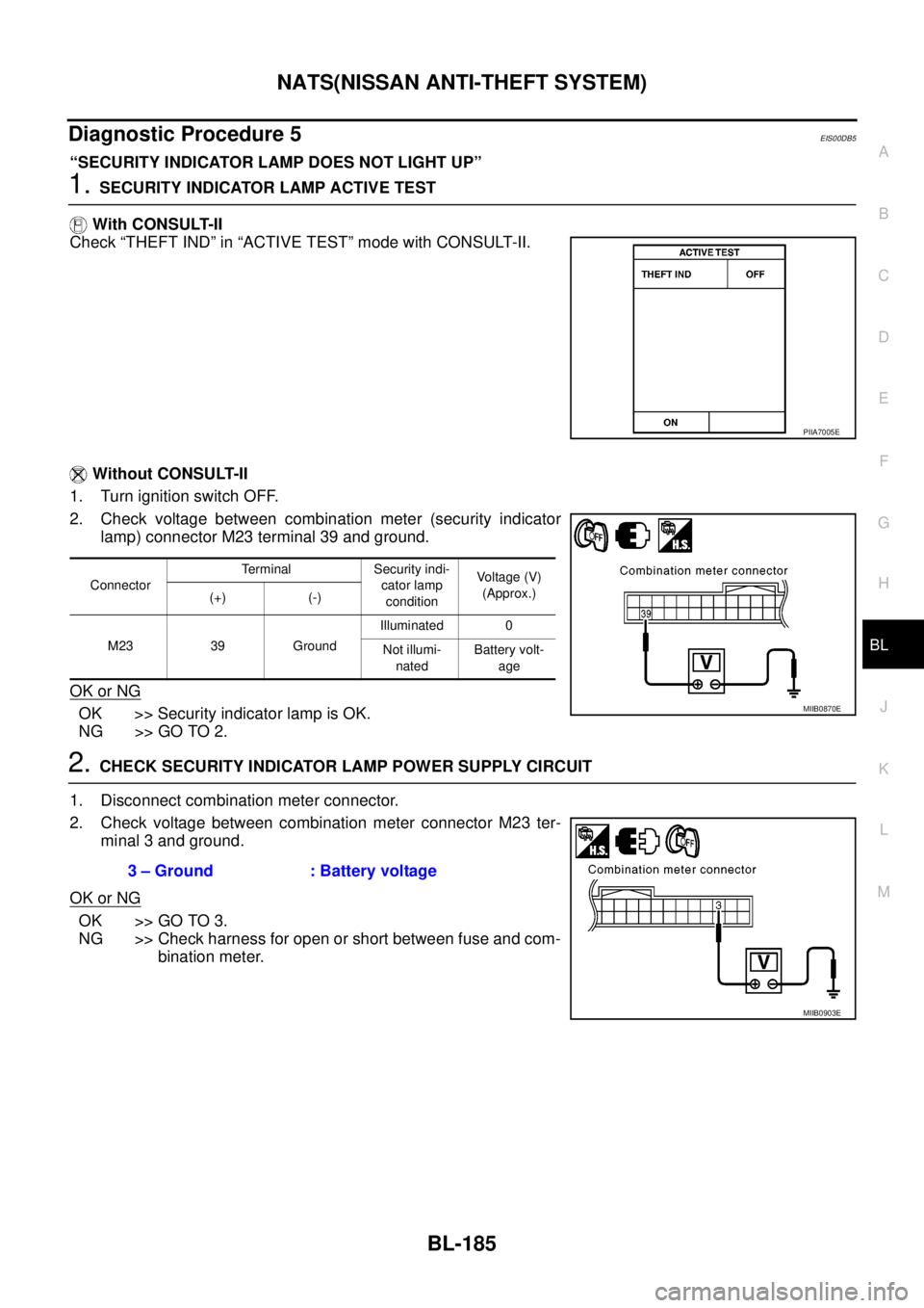
1.SECURITY INDICATOR LAMP ACTIVE TEST
With CONSULT-II
Check “THEFT IND” in “ACTIVE TEST” mode with CONSULT-II.
Without CONSULT-II
1. Turn ignition switch OFF.
2. Check voltage between combination meter (security indicator
lamp) connector M23 terminal 39 and ground.
OK or NG
OK >> Security indicator lamp is OK.
NG >> GO TO 2.
2.CHECK SECURITY INDICATOR LAMP POWER SUPPLY CIRCUIT
1. Disconnect combination meter connector.
2. Check voltage between combination meter connector M23 ter-
minal 3 and ground.
OK or NG
OK >> GO TO 3.
NG >> Check harness for open or short between fuse and com-
bination meter.
PIIA7005E
ConnectorTerminal Security indi-
cator lamp
conditionVoltage (V)
(Approx.)
(+) (-)
M23 39 GroundIlluminated 0
Not illumi-
natedBattery volt-
age
MIIB0870E
3 – Ground : Battery voltage
MIIB0903E
Page 770 of 3171
BL-186
NATS(NISSAN ANTI-THEFT SYSTEM)
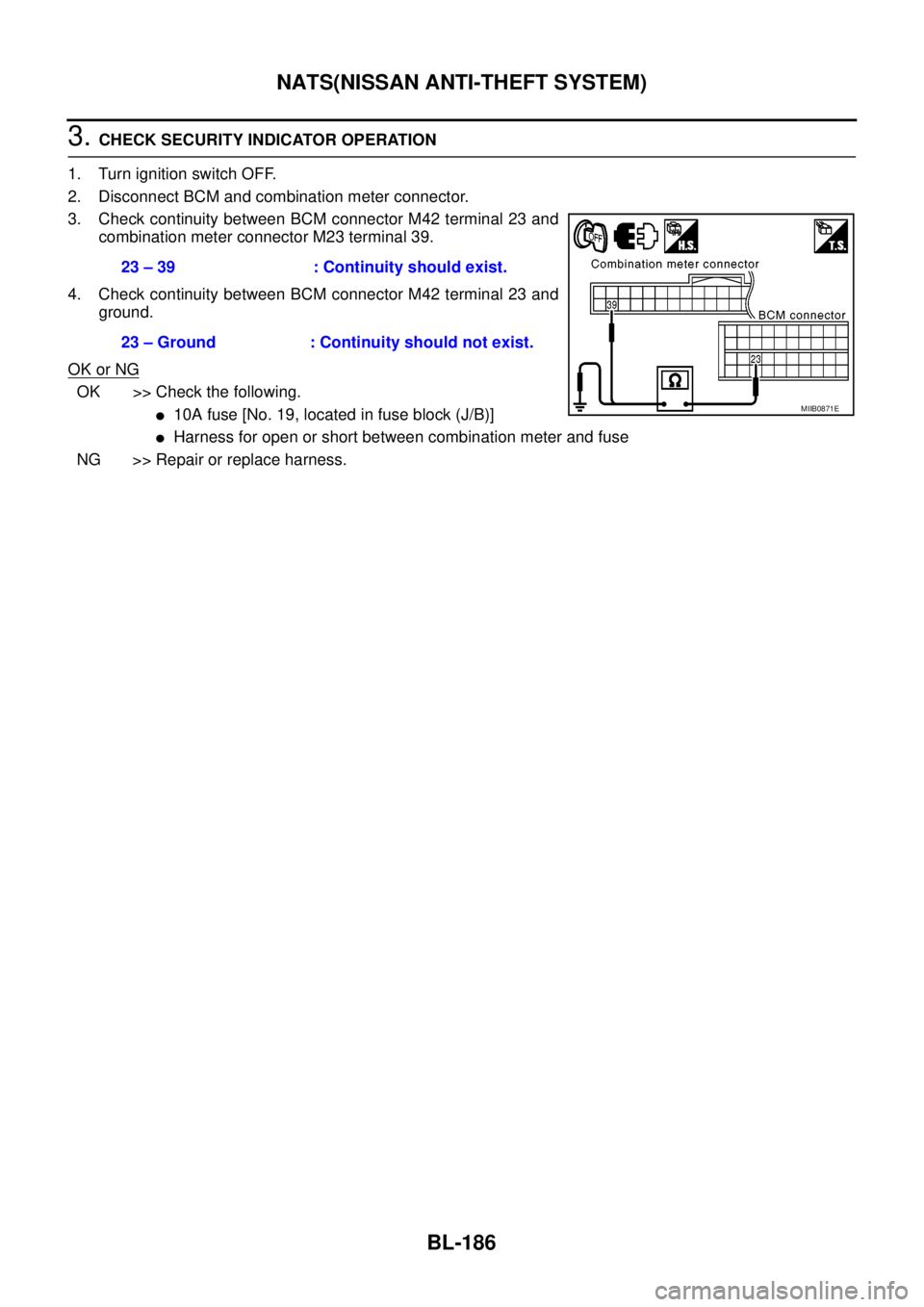
3.CHECK SECURITY INDICATOR OPERATION
1. Turn ignition switch OFF.
2. Disconnect BCM and combination meter connector.
3. Check continuity between BCM connector M42 terminal 23 and
combination meter connector M23 terminal 39.
4. Check continuity between BCM connector M42 terminal 23 and
ground.
OK or NG
OK >> Check the following.
l10A fuse [No. 19, located in fuse block (J/B)]
lHarness for open or short between combination meter and fuse
NG >> Repair or replace harness.23 – 39 : Continuity should exist.
23 – Ground : Continuity should not exist.
MIIB0871E