NISSAN NAVARA 2005 Repair Workshop Manual
NAVARA 2005
NISSAN
NISSAN
https://www.carmanualsonline.info/img/5/57362/w960_57362-0.png
NISSAN NAVARA 2005 Repair Workshop Manual
Trending: radiator, oil filter, Em 49, oil viscosity, rear view mirror, cooling, sensor
Page 771 of 3171
NATS(NISSAN ANTI-THEFT SYSTEM)
BL-187
C
D
E
F
G
H
J
K
L
MA
B
BL
Diagnostic Procedure 6EIS00DB6
Self-diagnostic results:
“LOCK MODE” displayed on CONSULT-II screen
1.CONFIRM SELF-DIAGNOSTIC RESULTS
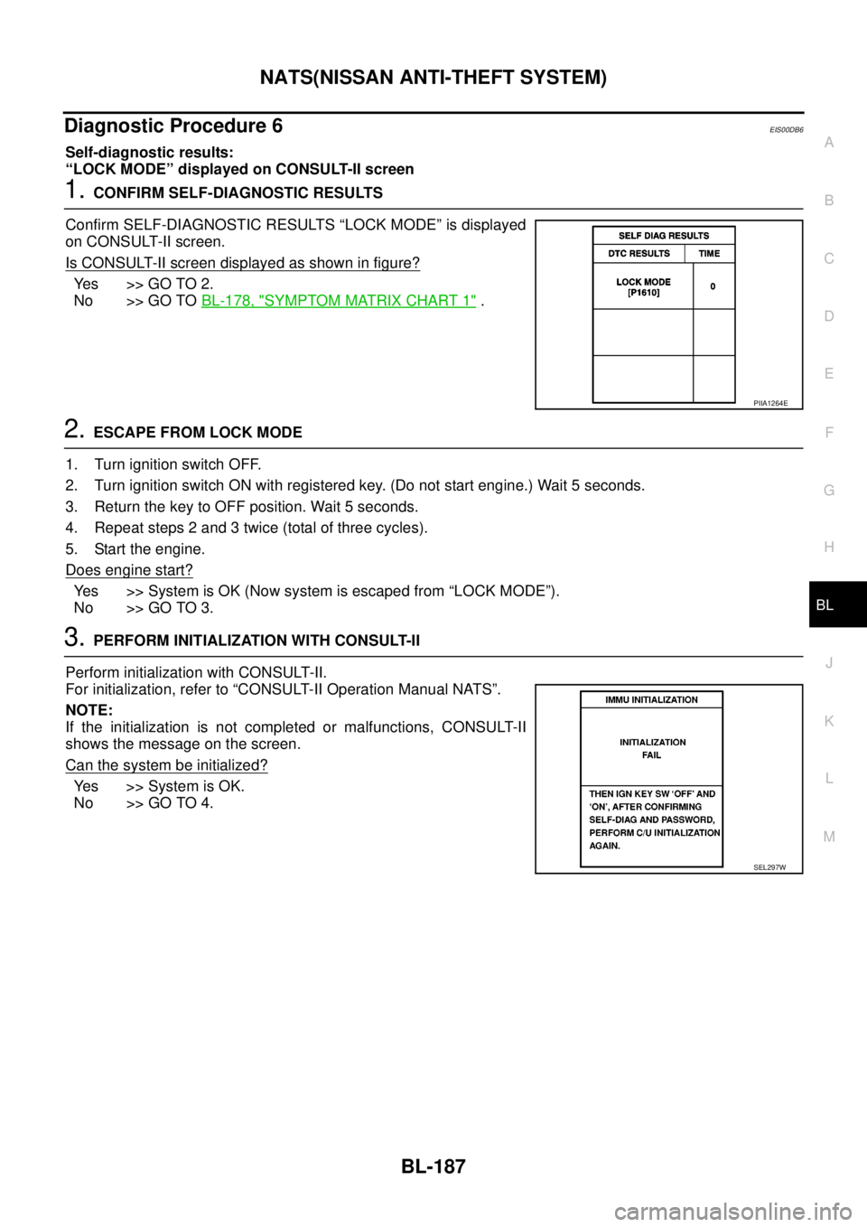
Confirm SELF-DIAGNOSTIC RESULTS “LOCK MODE” is displayed
on CONSULT-II screen.
Is CONSULT-II screen displayed as shown in figure?
Ye s > > G O T O 2 .
No >> GO TOBL-178, "
SYMPTOM MATRIX CHART 1".
2.ESCAPE FROM LOCK MODE
1. Turn ignition switch OFF.
2. Turn ignition switch ON with registered key. (Do not start engine.) Wait 5 seconds.
3. Return the key to OFF position. Wait 5 seconds.
4. Repeat steps 2 and 3 twice (total of three cycles).
5. Start the engine.
Does engine start?
Yes >>SystemisOK(Nowsystemisescapedfrom“LOCKMODE”).
No >> GO TO 3.
3.PERFORM INITIALIZATION WITH CONSULT-II
Perform initialization with CONSULT-II.
For initialization, refer to “CONSULT-II Operation Manual NATS”.
NOTE:
If the initialization is not completed or malfunctions, CONSULT-II
shows the message on the screen.
Can the system be initialized?
Yes >>SystemisOK.
No >> GO TO 4.
PIIA1264E
SEL297W
Page 772 of 3171
BL-188
NATS(NISSAN ANTI-THEFT SYSTEM)
4.PERFORM INITIALIZATION WITH CONSULT-II AGAIN
1. Replace BCM.
2. Perform initialization with CONSULT-II.
For initialization, refer to “CONSULT-II Operation Manual
NATS”.
NOTE:
If the initialization is not completed or malfunctions, CONSULT-II
shows the message on the screen.
Can the system be initialized?
Yes >>SystemisOK.(BCMismalfunctioning.)
No >> ECM is malfunctioning.
lReplace ECM.
lPerform initialization with CONSULT-II
lFor initialization, refer to “CONSULT-II Operation
Manual NATS”
Removal and Installation of NATS Antenna AmpEIS00DB7
REMOVAL
CAUTION:
Before servicing SRS, turn ignition switch OFF, disconnect both battery cables and wait at least 3 min-
utes.
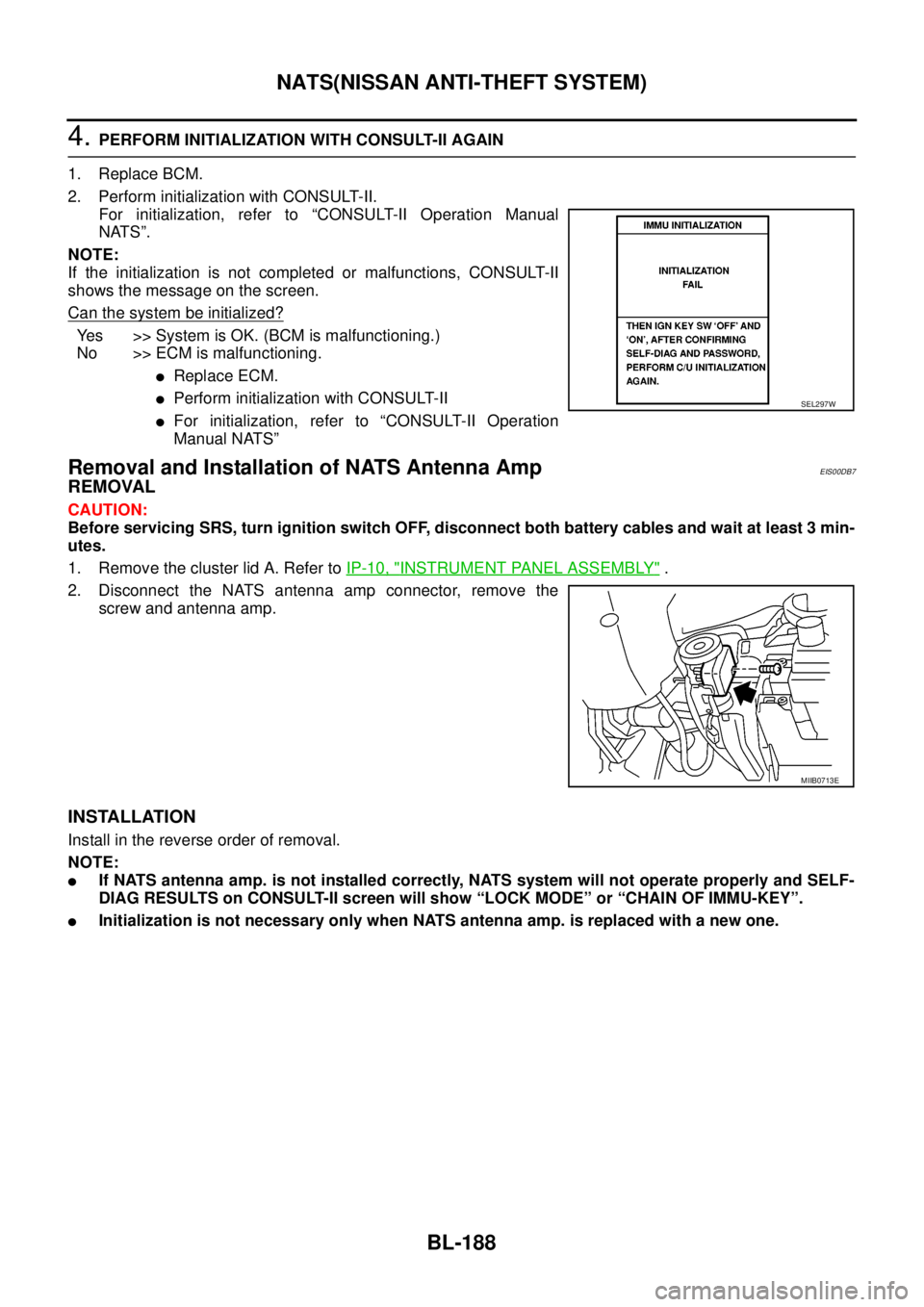
1. Remove the cluster lid A. Refer toIP-10, "
INSTRUMENT PANEL ASSEMBLY".
2. Disconnect the NATS antenna amp connector, remove the
screw and antenna amp.
INSTALLATION
Install in the reverse order of removal.
NOTE:
lIf NATS antenna amp. is not installed correctly, NATS system will not operate properly and SELF-
DIAG RESULTS on CONSULT-II screen will show “LOCK MODE” or “CHAIN OF IMMU-KEY”.
lInitialization is not necessary only when NATS antenna amp. is replaced with a new one.
SEL297W
MIIB0713E
Page 773 of 3171
CAB AND REAR BODY
BL-189
C
D
E
F
G
H
J
K
L
MA
B
BL
CAB AND REAR BODYPFP:93020
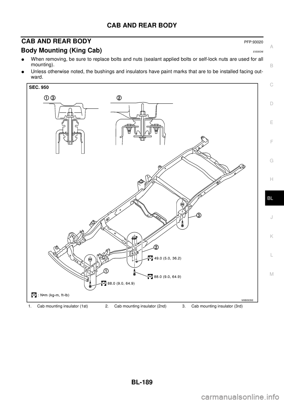
Body Mounting (King Cab)EIS00DI6
lWhen removing, be sure to replace bolts and nuts (sealant applied bolts or self-lock nuts are used for all
mounting).
lUnless otherwise noted, the bushings and insulators have paint marks that are to be installed facing out-
ward.
1. Cab mounting insulator (1st) 2. Cab mounting insulator (2nd) 3. Cab mounting insulator (3rd)
MIIB0935E
Page 774 of 3171
BL-190
CAB AND REAR BODY
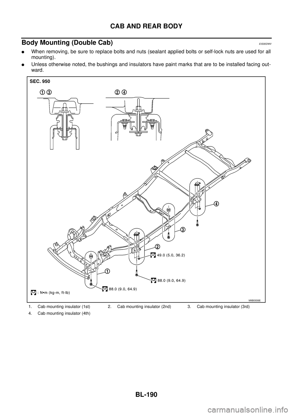
Body Mounting (Double Cab)
EIS00DWV
lWhen removing, be sure to replace bolts and nuts (sealant applied bolts or self-lock nuts are used for all
mounting).
lUnless otherwise noted, the bushings and insulators have paint marks that are to be installed facing out-
ward.
1. Cab mounting insulator (1st) 2. Cab mounting insulator (2nd) 3. Cab mounting insulator (3rd)
4. Cab mounting insulator (4th)
MIIB0936E
Page 775 of 3171
BODY REPAIR
BL-191
C
D
E
F
G
H
J
K
L
MA
B
BL
BODY REPAIRPFP:60100
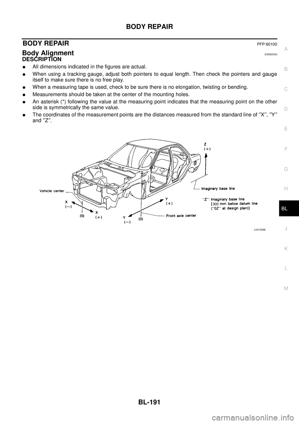
Body AlignmentEIS00DGG
DESCRIPTION
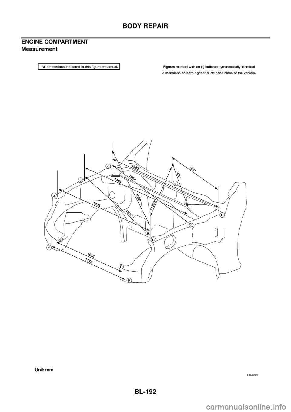
lAll dimensions indicated in the figures are actual.
lWhen using a tracking gauge, adjust both pointers to equal length. Then check the pointers and gauge
itself to make sure there is no free play.
lWhen a measuring tape is used, check to be sure there is no elongation, twisting or bending.
lMeasurements should be taken at the center of the mounting holes.
lAn asterisk (*) following the value at the measuring point indicates that the measuring point on the other
side is symmetrically the same value.
lThe coordinates of the measurement points are the distances measured from the standard line of²X²,²Y²
and²Z².
LIIA1506E
Page 776 of 3171
BL-192
BODY REPAIR
ENGINE COMPARTMENT
Measurement
LIIA1792E
Page 777 of 3171
BODY REPAIR
BL-193
C
D
E
F
G
H
J
K
L
MA
B
BL
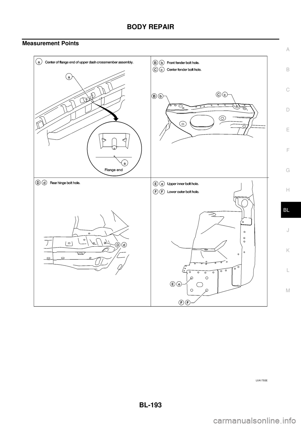
Measurement Points
LIIA1793E
Page 778 of 3171
BL-194
BODY REPAIR
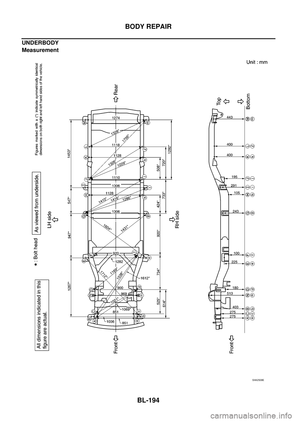
UNDERBODY
Measurement
SIIA2508E
Page 779 of 3171
BODY REPAIR
BL-195
C
D
E
F
G
H
J
K
L
MA
B
BL
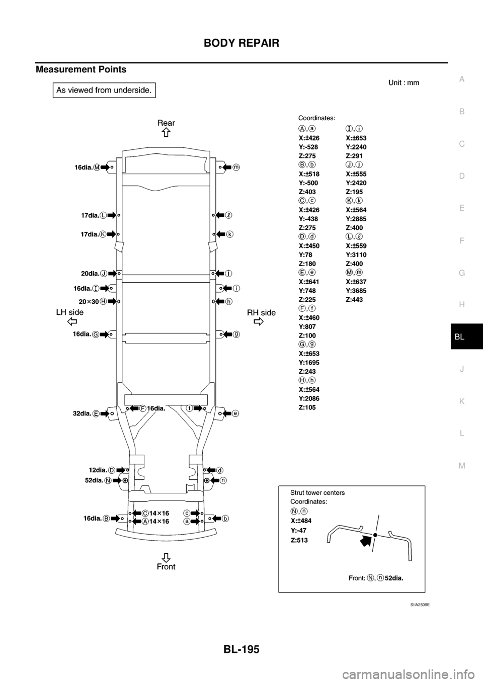
Measurement Points
SIIA2509E
Page 780 of 3171
BL-196
BODY REPAIR
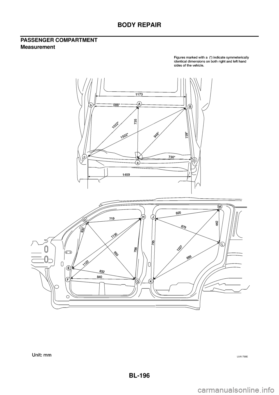
PASSENGER COMPARTMENT
Measurement
LIIA1798E
Trending: battery location, trailer, fuel reserve, start stop button, sport mode, maintenance schedule, steering


