NISSAN NOTE 2016 Service Repair Manual
Manufacturer: NISSAN, Model Year: 2016, Model line: NOTE, Model: NISSAN NOTE 2016Pages: 3641, PDF Size: 28.72 MB
Page 2051 of 3641
HA-26
< REMOVAL AND INSTALLATION >
COMPRESSOR
REMOVAL AND INSTALLATION
COMPRESSOR
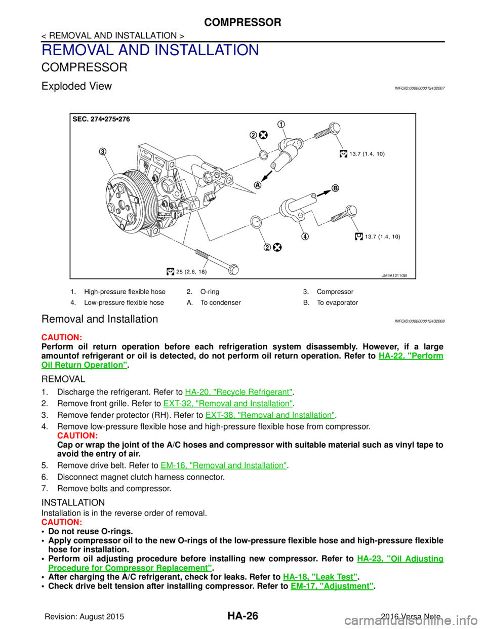
Exploded ViewINFOID:0000000012432007
Removal and InstallationINFOID:0000000012432008
CAUTION:
Perform oil return operation before each refrigeration system disassembly. However, if a large
amountof refrigerant or oil is detected, do not perform oil return operation. Refer to HA-22, "
Perform
Oil Return Operation".
REMOVAL
1. Discharge the refrigerant. Refer to HA-20, "Recycle Refrigerant".
2. Remove front grille. Refer to EXT-32, "
Removal and Installation".
3. Remove fender protector (RH). Refer to EXT-38, "
Removal and Installation".
4. Remove low-pressure flexible hose and high-pressure flexible hose from compressor. CAUTION:
Cap or wrap the joint of the A/C hoses and compr essor with suitable material such as vinyl tape to
avoid the entry of air.
5. Remove drive belt. Refer to EM-16, "
Removal and Installation".
6. Disconnect magnet clutch harness connector.
7. Remove bolts and compressor.
INSTALLATION
Installation is in the reverse order of removal.
CAUTION:
• Do not reuse O-rings.
• Apply compressor oil to the new O-rings of the low-pressure flexible hose an d high-pressure flexible
hose for installation.
• Perform oil adjusting procedure before installing new compressor. Refer to HA-23, "
Oil Adjusting
Procedure for Compressor Replacement".
• After charging the A/C refrig erant, check for leaks. Refer to HA-18, "
Leak Test".
• Check drive belt tension after installing compressor. Refer to EM-17, "
Adjustment".
JMIIA1211GB
1. High-pressure flexible hose 2. O-ring 3. Compressor
4. Low-pressure flexible hose A. To condenser B. To evaporator
Revision: August 2015 2016 Versa Note
cardiagn.com
Page 2052 of 3641
COMPRESSORHA-27
< REMOVAL AND INSTALLATION >
C
DE
F
G H
J
K L
M A
B
HA
N
O P
InspectionINFOID:0000000012432009
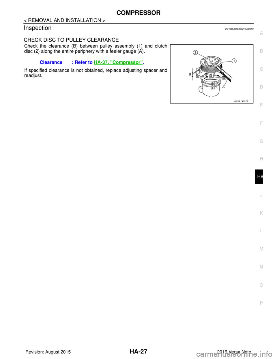
CHECK DISC TO PULLEY CLEARANCE
Check the clearance (B) between pulley assembly (1) and clutch
disc (2) along the entire periphery with a feeler gauge (A).
If specified clearance is not obtained, replace adjusting spacer and
readjust. Clearance : Refer to HA-37, "
Compressor".
AWIIA1462ZZ
Revision: August 2015
2016 Versa Note
cardiagn.com
Page 2053 of 3641
HA-28
< REMOVAL AND INSTALLATION >
COOLER PIPE AND HOSE
COOLER PIPE AND HOSE
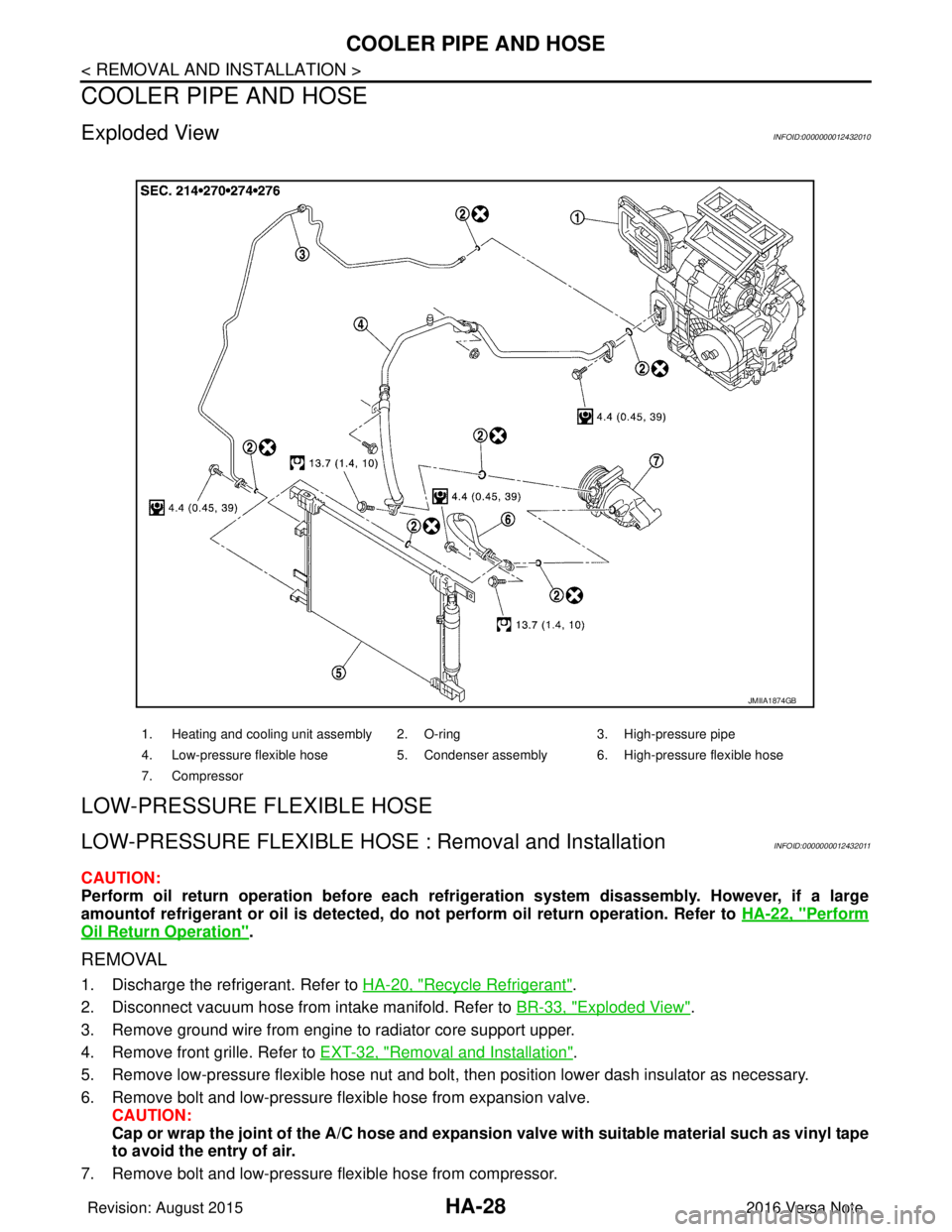
Exploded ViewINFOID:0000000012432010
LOW-PRESSURE FLEXIBLE HOSE
LOW-PRESSURE FLEXIBLE HOSE : Removal and InstallationINFOID:0000000012432011
CAUTION:
Perform oil return operation before each refrigeration system disassembly. However, if a large
amountof refrigerant or oil is detected, do not perform oil return operation. Refer to HA-22, "
Perform
Oil Return Operation".
REMOVAL
1. Discharge the refrigerant. Refer to HA-20, "Recycle Refrigerant".
2. Disconnect vacuum hose from intake manifold. Refer to BR-33, "
Exploded View".
3. Remove ground wire from engine to radiator core support upper.
4. Remove front grille. Refer to EXT-32, "
Removal and Installation".
5. Remove low-pressure flexible hose nut and bolt, then position lower dash insulator as necessary.
6. Remove bolt and low-pressure flexible hose from expansion valve. CAUTION:
Cap or wrap the joint of the A/C hose and expansion valve with suitable material such as vinyl tape
to avoid the entry of air.
7. Remove bolt and low-pressure flexible hose from compressor.
1. Heating and cooling unit assembly 2. O-ring 3. High-pressure pipe
4. Low-pressure flexible hose 5. Condenser assembly 6. High-pressure flexible hose
7. Compressor
JMIIA1874GB
Revision: August 2015 2016 Versa Note
cardiagn.com
Page 2054 of 3641
COOLER PIPE AND HOSEHA-29
< REMOVAL AND INSTALLATION >
C
DE
F
G H
J
K L
M A
B
HA
N
O P
CAUTION:
Cap or wrap the joint of the A/ C hose and compressor with suitable material such as vinyl tape to
avoid the entry of air.
INSTALLATION
Installation is in the reverse order of removal.
CAUTION:
• Do not reuse O-rings.
• Apply compressor oil to new O-rings of low-pressure flexible hose for installation.
• After charging refrigerant, check for leaks. Refer to HA-18, "
Leak Test".
HIGH-PRESSURE FLEXIBLE HOSE
HIGH-PRESSURE FLEXIBLE HOSE : Removal and InstallationINFOID:0000000012432012
CAUTION:
Perform oil return operation before each refrigeration system disassembly. However, if a large
amountof refrigerant or oil is detected, do not perform oil return operation. Refer to HA-22, "
Perform
Oil Return Operation".
REMOVAL
1. Discharge the refrigerant. Refer to HA-20, "Recycle Refrigerant".
2. Remove front grille. Refer to EXT-32, "
Removal and Installation".
3. Remove bolt and high-pressure flexible hose from condenser. CAUTION:
Cap or wrap the joint of the A/C hose and condenser with suitable material such as vinyl tape to
avoid the entry of air.
4. Remove bolt and high-pressure flexible hose from compressor. CAUTION:
Cap or wrap the joint of the A/ C hose and compressor with suitable material such as vinyl tape to
avoid the entry of air.
INSTALLATION
Installation is in the reverse order of removal.
CAUTION:
• Do not reuse O-rings.
• Apply compressor oil to new O-rings of the high-pressure flexible hose for installation.
• After charging refrigerant, check for leaks. Refer to HA-18, "
Leak Test".
HIGH-PRESSURE PIPE
HIGH-PRESSURE PIPE : Removal and InstallationINFOID:0000000012432013
REMOVAL
1. Discharge the refrigerant. Refer to HA-20, "Recycle Refrigerant".
2. Remove radiator core support upper. Refer to DLK-144, "
RADIATOR CORE SUPPORT UPPER :
Removal and Installation".
3. Remove low-pressure flexible hose. Refer to HA-28, "
LOW-PRESSURE FLEXIBLE HOSE : Removal and
Installation".
4. Remove high-pressure flexible hose. Refer to HA-29, "
HIGH-PRESSURE FLEXIBLE HOSE : Removal
and Installation".
5. Disconnect high-pressure pipe from expansion valve. CAUTION:
Cap or wrap the joint of the A/C piping and expan sion valve with suitable material such as vinyl
tape to avoid the entry of air.
6. Remove bolt and high-pressure pipe from condenser. CAUTION:
Cap or wrap the joint of the A/C piping and conden ser with suitable material such as vinyl tape to
avoid the entry of air.
7. Release clips and remove high-pressure pipe from vehicle.
Revision: August 2015 2016 Versa Note
cardiagn.com
Page 2055 of 3641

HA-30
< REMOVAL AND INSTALLATION >
COOLER PIPE AND HOSE
INSTALLATION
Installation is in the reverse order of removal.
CAUTION:
• Do not reuse O-rings.
• Apply compressor oil to new O-rings of the high-pressure pipe for installation.
• After charging refrigerant, check for leaks. Refer to HA-18, "
Leak Test".
Revision: August 2015 2016 Versa Note
cardiagn.com
Page 2056 of 3641
CONDENSERHA-31
< REMOVAL AND INSTALLATION >
C
DE
F
G H
J
K L
M A
B
HA
N
O P
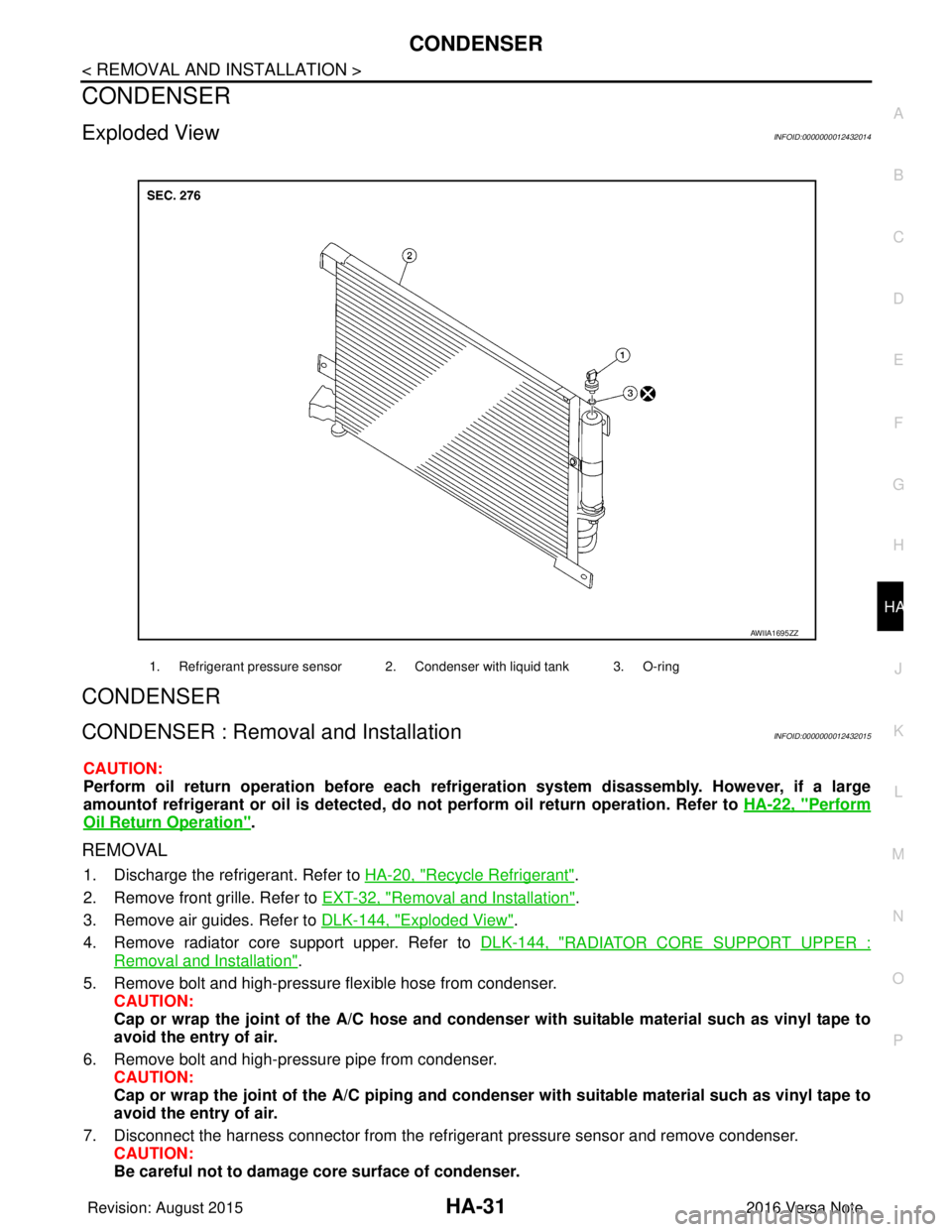
CONDENSER
Exploded ViewINFOID:0000000012432014
CONDENSER
CONDENSER : Remova l and InstallationINFOID:0000000012432015
CAUTION:
Perform oil return operation be fore each refrigeration system disassembly. However, if a large
amountof refrigerant or oil is detected, do not perform oil return operation. Refer to HA-22, "
Perform
Oil Return Operation".
REMOVAL
1. Discharge the refrigerant. Refer to HA-20, "Recycle Refrigerant".
2. Remove front grille. Refer to EXT-32, "
Removal and Installation".
3. Remove air guides. Refer to DLK-144, "
Exploded View".
4. Remove radiator core support upper. Refer to DLK-144, "
RADIATOR CORE SUPPORT UPPER :
Removal and Installation".
5. Remove bolt and high-pressure flexible hose from condenser. CAUTION:
Cap or wrap the joint of the A/C hose and condenser with suitable material such as vinyl tape to
avoid the entry of air.
6. Remove bolt and high-pressure pipe from condenser. CAUTION:
Cap or wrap the joint of the A/C piping and conden ser with suitable material such as vinyl tape to
avoid the entry of air.
7. Disconnect the harness connector from the refri gerant pressure sensor and remove condenser.
CAUTION:
Be careful not to damage core surface of condenser.
1. Refrigerant pressure sensor 2. Condenser with liquid tank 3. O-ring
AWIIA1695ZZ
Revision: August 2015 2016 Versa Note
cardiagn.com
Page 2057 of 3641
HA-32
< REMOVAL AND INSTALLATION >
CONDENSER
INSTALLATION
Installation is in the reverse order of removal.
CAUTION:
• Do not reuse O-rings.
• Apply compressor oil to new O-rings of the high-pressure flexible hose and high-pressure pipe forinstallation.
• Perform oil adjusting procedure before installing new condenser. Refer to HA-22, "
Oil Adjusting Pro-
cedure for Components Replacement Except Compressor".
• After charging refrigerant, check for leaks. Refer to HA-18, "
Leak Test".
LIQUID TANK
LIQUID TANK : Removal and Installation of Liquid TankINFOID:0000000012432016
The liquid tank is only serviced as part of the condenser. Refer to HA-31, "CONDENSER : Removal and Instal-
lation".
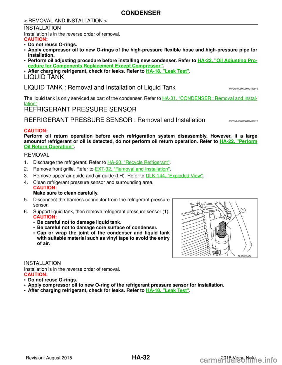
REFRIGERANT PRESSURE SENSOR
REFRIGERANT PRESSURE SENSOR : Removal and InstallationINFOID:0000000012432017
CAUTION:
Perform oil return operation before each refrigeration system disassembly. However, if a large
amountof refrigerant or oil is detected, do not perform oil return operation. Refer to HA-22, "
Perform
Oil Return Operation".
REMOVAL
1. Discharge the refrigerant. Refer to HA-20, "Recycle Refrigerant".
2. Remove front grille. Refer to EXT-32, "
Removal and Installation".
3. Remove upper air guide and air guide (LH). Refer to DLK-144, "
Exploded View".
4. Clean refrigerant pressure sensor and surrounding area. CAUTION:
Make sure to clean carefully.
5. Disconnect the harness connector from the refrigerant pressure sensor.
6. Support liquid tank, then remove refrigerant pressure sensor (1). CAUTION:
• Be careful not to damage liquid tank.
• Be careful not to damage core surface of condenser.
• Cap or wrap the joint of the condenser and liquid tank
with suitable material such as vinyl tape to avoid the entry
of air.
INSTALLATION
Installation is in the reverse order of removal.
CAUTION:
• Do not reuse O-rings.
• Apply compressor oil to new O-ring of the refrigerant pressure sensor for installation.
• After charging refrigerant, check for leaks. Refer to HA-18, "
Leak Test".
ALIIA0004ZZ
Revision: August 2015 2016 Versa Note
cardiagn.com
Page 2058 of 3641
HEATING AND COOLING UNIT ASSEMBLYHA-33
< REMOVAL AND INSTALLATION >
C
DE
F
G H
J
K L
M A
B
HA
N
O P
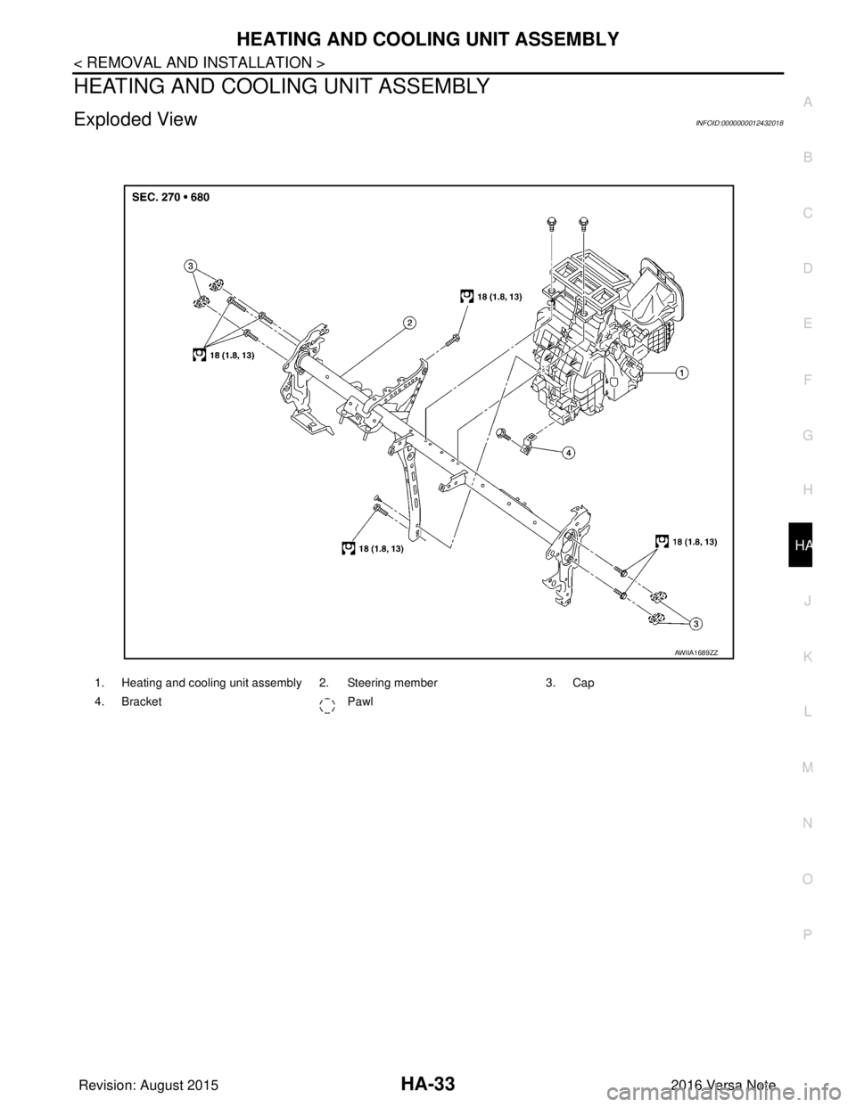
HEATING AND COOLING UNIT ASSEMBLY
Exploded ViewINFOID:0000000012432018
1. Heating and cooling unit assembly 2. Steering member 3. Cap
4. Bracket Pawl
AWIIA1689ZZ
Revision: August 2015 2016 Versa Note
cardiagn.com
Page 2059 of 3641
HA-34
< REMOVAL AND INSTALLATION >
HEATING AND COOLING UNIT ASSEMBLY
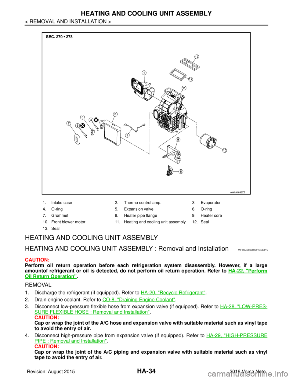
HEATING AND COOLING UNIT ASSEMBLY
HEATING AND COOLING UNIT ASSEMBLY : Removal and InstallationINFOID:0000000012432019
CAUTION:
Perform oil return operation before each refrigeration system disassembly. However, if a large
amountof refrigerant or oil is detected, do not perform oil return operation. Refer to HA-22, "
Perform
Oil Return Operation".
REMOVAL
1. Discharge the refrigerant (if equipped). Refer to HA-20, "Recycle Refrigerant".
2. Drain engine coolant. Refer to CO-8, "
Draining Engine Coolant".
3. Disconnect low-pressure flexible hose from expansion valve (if equipped). Refer to HA-28, "
LOW-PRES-
SURE FLEXIBLE HOSE : Removal and Installation".
CAUTION:
Cap or wrap the joint of the A/C hose and expansion valve with suitable material such as vinyl tape
to avoid the entry of air.
4. Disconnect high-pressure pipe from expansion valve (if equipped). Refer to HA-29, "
HIGH-PRESSURE
PIPE : Removal and Installation".
CAUTION:
Cap or wrap the joint of the A/C piping and expans ion valve with suitable material such as vinyl
tape to avoid the entry of air.
1. Intake case 2. Thermo control amp. 3. Evaporator
4. O-ring 5. Expansion valve 6. O-ring
7. Grommet 8. Heater pipe flange 9. Heater core
10. Front blower motor 11. Heating and cooling unit assembly 12. Seal
13. Seal
AWIIA1696ZZ
Revision: August 2015 2016 Versa Note
cardiagn.com
Page 2060 of 3641
HEATING AND COOLING UNIT ASSEMBLYHA-35
< REMOVAL AND INSTALLATION >
C
DE
F
G H
J
K L
M A
B
HA
N
O P
5. Disconnect heater hoses from heater core.
6. Remove instrument panel assembly. Refer to IP-15, "
Removal and Installation".
7. Disconnect evaporator drain hose from heating and cooling unit assembly.
8. Disconnect harness connectors, grounds, retainers, etc. , and remove bolts required to remove steering
member.
9. Remove steering member and heating and cooling unit assembly.
10. Remove heating and cooling unit assembly from steering member. Refer to HA-33, "
Exploded View".
INSTALLATION
Installation is in the reverse order of removal.
CAUTION:
• Do not reuse O-rings.
• Apply compressor oil to new O-rings of the low-pressure flexible hose and high-pressure pipe for
installation.
• After charging refrigerant, check for leaks. Refer to HA-18, "
Leak Test".
NOTE:
When refilling engine coolant, refer to CO-9, "
Refilling".
HEATER CORE
HEATER CORE : Removal and InstallationINFOID:0000000012432020
REMOVAL
1. Remove the heating and cooling unit assembly. Refer to HA-34, "HEATING AND COOLING UNIT
ASSEMBLY : Removal and Installation".
2. Remove foot duct (LH). Refer to VTL-7, "
FOOT DUCT : Removal and Installation".
3. Remove heater packing.
4. Remove heater pipe flange.
5. Remove heater core.
INSTALLATION
Installation is in the reverse order of removal.
NOTE:
When refilling engine coolant, refer to CO-9, "
Refilling".
EVAPORATOR
EVAPORATOR : Removal and InstallationINFOID:0000000012432021
REMOVAL
1. Remove heating and cooling unit assembly. Refer to HA-34, "HEATING AND COOLING UNIT ASSEM-
BLY : Removal and Installation".
2. Remove foot duct (RH). Refer to VTL-7, "
FOOT DUCT : Removal and Installation".
3. Remove intake case. Refer to HA-33, "
Exploded View".
4. Remove expansion valve. Refer to HA-36, "
EXPANSION VALVE : Removal and Installation".
5. Remove evaporator cover and evaporator assembly.
INSTALLATION
Installation is in the reverse order of removal.
CAUTION:
• Do not reuse O-rings.
• Apply compressor oil to ne w O-rings for installation.
• Perform oil adjusting procedure afte r installing new evaporator. Refer to HA-22, "
Oil Adjusting Pro-
cedure for Components Replacement Except Compressor".
• After charging refrigerant, check for leaks. Refer to HA-18, "
Leak Test".
EXPANSION VALVE
Revision: August 2015 2016 Versa Note
cardiagn.com