NISSAN NOTE 2016 Service Repair Manual
Manufacturer: NISSAN, Model Year: 2016, Model line: NOTE, Model: NISSAN NOTE 2016Pages: 3641, PDF Size: 28.72 MB
Page 2031 of 3641

HA-6
< PRECAUTION >
PRECAUTIONS
• The air conditioner warranty is void if the vehicle is within the warranty period. Please contact Nissan Cus-tomer Affairs for further assistance.
COMPRESSOR
CAUTION:
• Cap or plug all openings to prevent moisture and fo reign matter from entering.
• Store it in the same way as it is when moun ted on the car when the compressor is removed.
• Follow “Maintenance of Oil Level” exactly when replacing or repairing compressor. Refer to HA-22,
"Description".
• Keep friction surfaces between clut ch and pulley clean. Wipe it off by using a clean waste cloth
moistened with thinner if the su rface is contaminated with oil.
• Turn the compressor shaft by hand more than five turns in both directions after compressor service
operation. This distributes oil e qually inside the compressor. Let the engine idle and operate the
compressor for one hour after the compressor is installed.
• Apply voltage to the new one and check for norma l operation after replacing the compressor magnet
clutch.
LEAK DETECTION DYE
CAUTION:
• The A/C system contains a fluorescent leak detect ion dye used for locating refrigerant leaks. An
ultraviolet (UV) lamp is required to il luminate the dye when inspecting for leaks.
• Always wear fluorescence enhancing UV safety goggles to protect eyes and enhance the visibility of the fluorescent dye.
• The fluorescent dye leak detector is not a replacement for an electrical l eak detector (SST: J-41995).
The fluorescent dye leak detector sh ould be used in conjunction with an electrical leak detector
(SST: J-41995) to pin-point refrigerant leaks.
• Read and follow all manufacture’s operating inst ructions and precautions prior to performing the
work for the purpose of safet y and customer’s satisfaction.
• A compressor shaft seal should not necessarily be repaired becau se of dye seepage. The compres-
sor shaft seal should only be repaired after confi rming the leak with an electrical leak detector (SST:
J-41995).
• Always remove any remaining dye from the leak area after repairs are completed to avoid a misdiag-
nosis during a future service.
• Do not allow dye to come into contact with painted body panels or interior components. Clean imme- diately with the approved dye cl eaner if dye is spilled. Fluorescent dye left on a surface for an
extended period of time cannot be removed.
• Do not spray the fluorescent dye cleaning agent on hot surfaces (engine exhaust manifold, etc.).
• Do not use more than one refrigerant dye bottle [1/4 ounce (7.4 cc)] per A/C system.
• Leak detection dyes for HFC-134a (R-134a) and CFC-12 (R-12) A/C systems are different. Do not use
HFC-134a (R-134a) leak detection dye in CFC-12 (R- 12) A/C system or CFC-12 (R-12) leak detection
dye in HFC-134a (R-134a) A/C system or A/C system damage may result.
• The fluorescent properties of the dye remains fo r three or more years unless a compressor malfunc-
tion occurs.
NOTE: Identification
• Vehicles with factory installed fluorescent dye have a green label.
• Vehicles without factory installed fluorescent dye have a blue label.
Service EquipmentINFOID:0000000012431988
RECOVERY/RECYCLING RECHARGING EQUIPMENT
Be certain to follow the manufacturer’s instructions for machine operation and machine maintenance. Do not
introduce any refrigerant other than that specified into the machine.
ELECTRONIC LEAK DETECTOR
Be certain to follow the manufacturer’s instruct ions for tester operation and tester maintenance.
VACUUM PUMP
Revision: August 2015 2016 Versa Note
cardiagn.com
Page 2032 of 3641
PRECAUTIONSHA-7
< PRECAUTION >
C
DE
F
G H
J
K L
M A
B
HA
N
O P
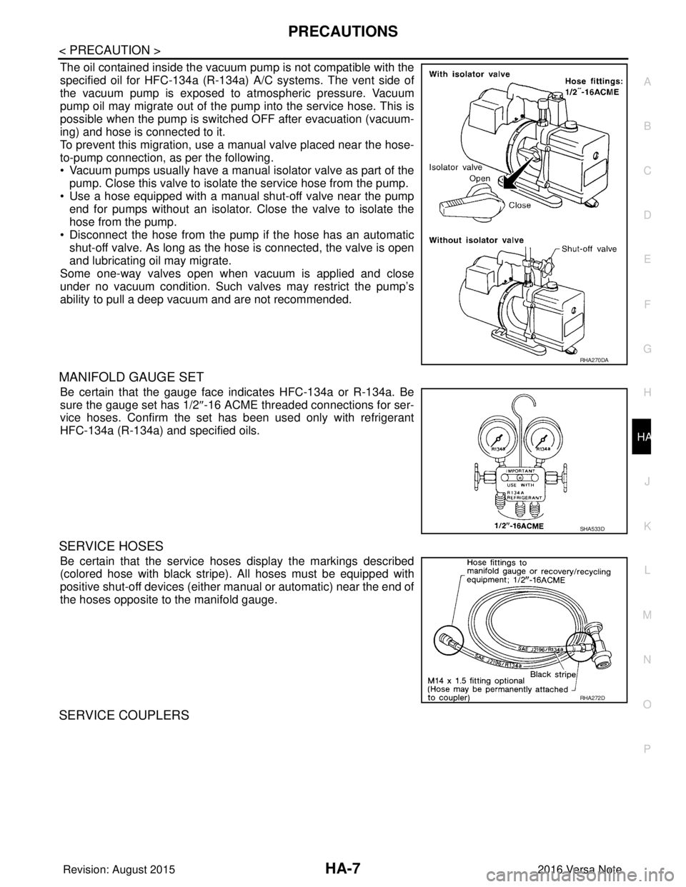
The oil contained inside the vacuum pump is not compatible with the
specified oil for HFC-134a (R-134a) A/C systems. The vent side of
the vacuum pump is exposed to atmospheric pressure. Vacuum
pump oil may migrate out of the pump into the service hose. This is
possible when the pump is switc hed OFF after evacuation (vacuum-
ing) and hose is connected to it.
To prevent this migration, use a manual valve placed near the hose-
to-pump connection, as per the following.
• Vacuum pumps usually have a manual isolator valve as part of the
pump. Close this valve to isolate the service hose from the pump.
• Use a hose equipped with a manual shut-off valve near the pump end for pumps without an isolator. Close the valve to isolate the
hose from the pump.
• Disconnect the hose from the pump if the hose has an automatic shut-off valve. As long as the hose is connected, the valve is open
and lubricating oil may migrate.
Some one-way valves open when vacuum is applied and close
under no vacuum condition. Such valves may restrict the pump’s
ability to pull a deep vacuum and are not recommended.
MANIFOLD GAUGE SET
Be certain that the gauge face indicates HFC-134a or R-134a. Be
sure the gauge set has 1/2 ″-16 ACME threaded connections for ser-
vice hoses. Confirm the set has been used only with refrigerant
HFC-134a (R-134a) and specified oils.
SERVICE HOSES
Be certain that the service hoses display the markings described
(colored hose with black stripe) . All hoses must be equipped with
positive shut-off devices (either manual or automatic) near the end of
the hoses opposite to the manifold gauge.
SERVICE COUPLERS
RHA270DA
SHA533D
RHA272D
Revision: August 2015 2016 Versa Note
cardiagn.com
Page 2033 of 3641
HA-8
< PRECAUTION >
PRECAUTIONS
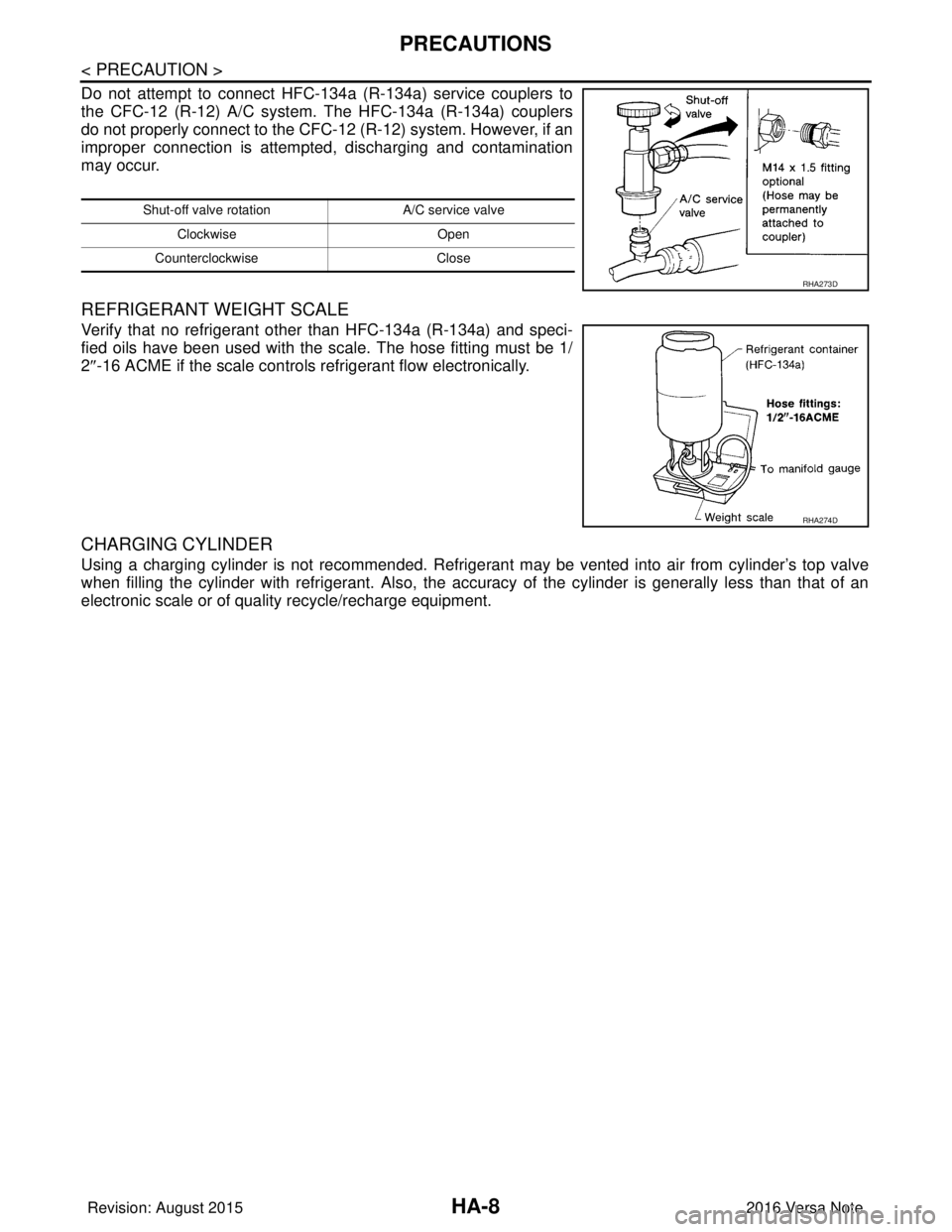
Do not attempt to connect HFC-134a (R-134a) service couplers to
the CFC-12 (R-12) A/C system. The HFC-134a (R-134a) couplers
do not properly connect to the CFC-12 (R-12) system. However, if an
improper connection is attempted, discharging and contamination
may occur.
REFRIGERANT WEIGHT SCALE
Verify that no refrigerant other than HFC-134a (R-134a) and speci-
fied oils have been used with the scale. The hose fitting must be 1/
2 ″-16 ACME if the scale controls refrigerant flow electronically.
CHARGING CYLINDER
Using a charging cylinder is not recommended. Refrigerant may be vented into air from cylinder’s top valve
when filling the cylinder with refrigerant. Also, the accuracy of the cylinder is generally less than that of an
electronic scale or of quality recycle/recharge equipment.
Shut-off valve rotati on A/C service valve
Clockwise Open
Counterclockwise Close
RHA273D
RHA274D
Revision: August 2015 2016 Versa Note
cardiagn.com
Page 2034 of 3641
PREPARATIONHA-9
< PREPARATION >
C
DE
F
G H
J
K L
M A
B
HA
N
O P
PREPARATION
PREPARATION
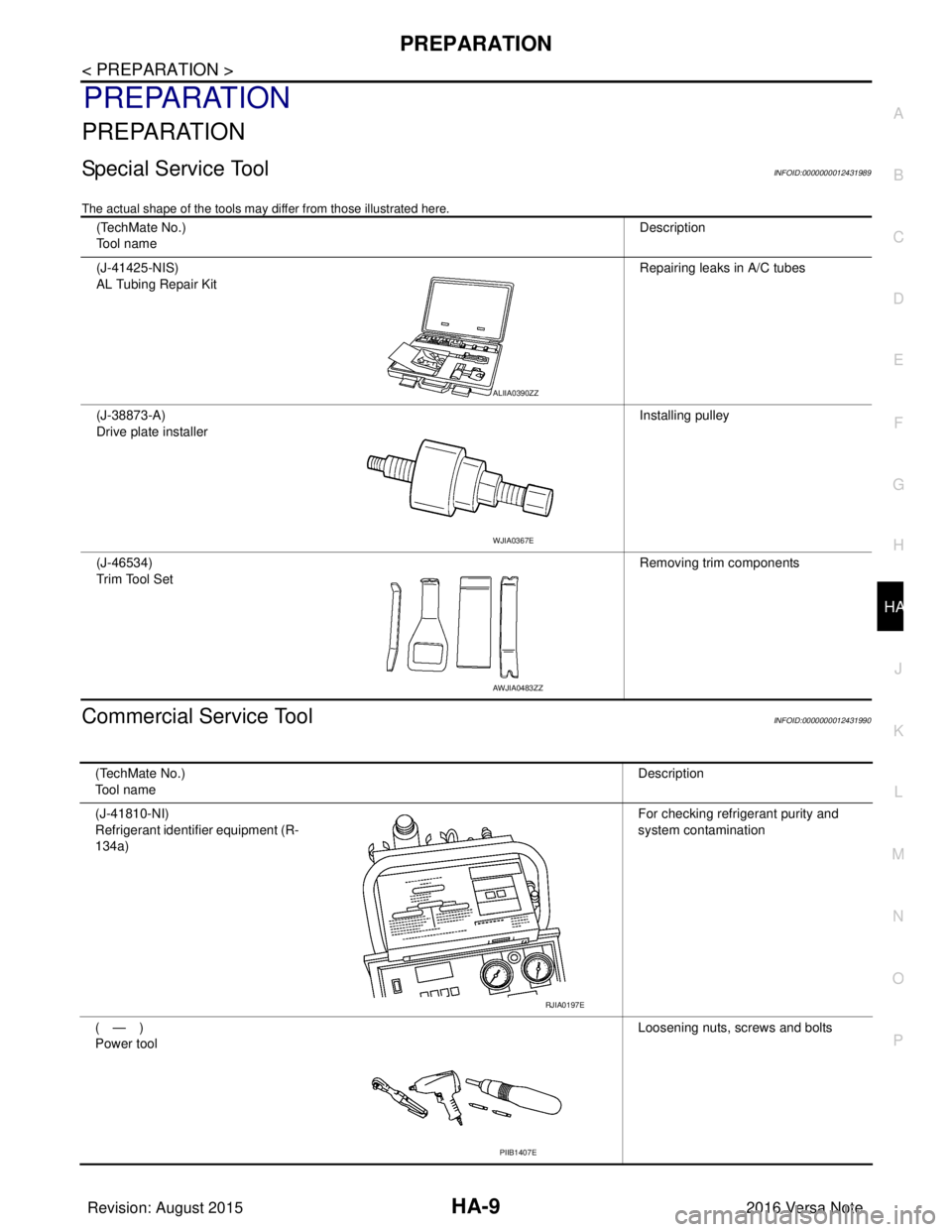
Special Service ToolINFOID:0000000012431989
The actual shape of the tools may di ffer from those illustrated here.
Commercial Service ToolINFOID:0000000012431990
(TechMate No.)
Tool name Description
(J-41425-NIS)
AL Tubing Repair Kit Repairing leaks in A/C tubes
(J-38873-A)
Drive plate installer Installing pulley
(J-46534)
Trim Tool Set Removing trim components
ALIIA0390ZZ
WJIA0367E
AWJIA0483ZZ
(TechMate No.)
Tool nameDescription
(J-41810-NI)
Refrigerant identifier equipment (R-
134a) For checking refrigerant purity and
system contamination
(—)
Power tool Loosening nuts, screws and bolts
RJIA0197E
PIIB1407E
Revision: August 2015
2016 Versa Note
cardiagn.com
Page 2035 of 3641
HA-10
< PREPARATION >
PREPARATION
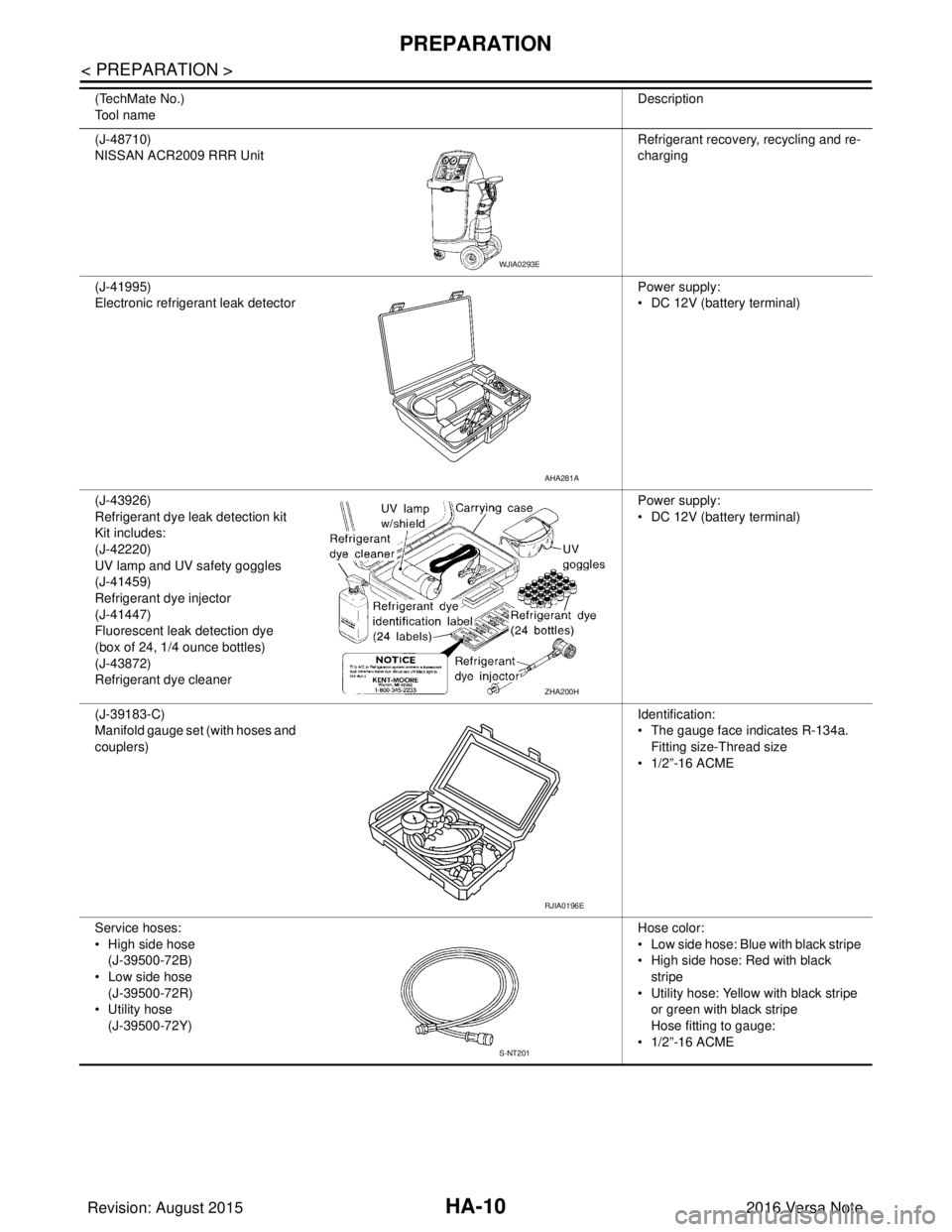
(J-48710)
NISSAN ACR2009 RRR UnitRefrigerant recovery
, recycling and re-
charging
(J-41995)
Electronic refrigerant leak detector Power supply:
• DC 12V (battery terminal)
(J-43926)
Refrigerant dye leak detection kit
Kit includes:
(J-42220)
UV lamp and UV safety goggles
(J-41459)
Refrigerant dye injector
(J-41447)
Fluorescent leak detection dye
(box of 24, 1/4 ounce bottles)
(J-43872)
Refrigerant dye cleaner Power supply:
• DC 12V (battery terminal)
(J-39183-C)
Manifold gauge set (with hoses and
couplers) Identification:
• The gauge face indicates R-134a.
Fitting size-Thread size
• 1/2”-16 ACME
Service hoses:
• High side hose (J-39500-72B)
• Low side hose (J-39500-72R)
• Utility hose (J-39500-72Y) Hose color:
• Low side hose: Blue with black stripe
• High side hose: Red with black
stripe
• Utility hose: Yellow with black stripe
or green with black stripe
Hose fitting to gauge:
• 1/2”-16 ACME
(TechMate No.)
Tool name
Description
WJIA0293E
AHA281A
ZHA200H
RJIA0196E
S-NT201
Revision: August 2015
2016 Versa Note
cardiagn.com
Page 2036 of 3641
PREPARATIONHA-11
< PREPARATION >
C
DE
F
G H
J
K L
M A
B
HA
N
O P
Sealant and/or OilINFOID:0000000012431991
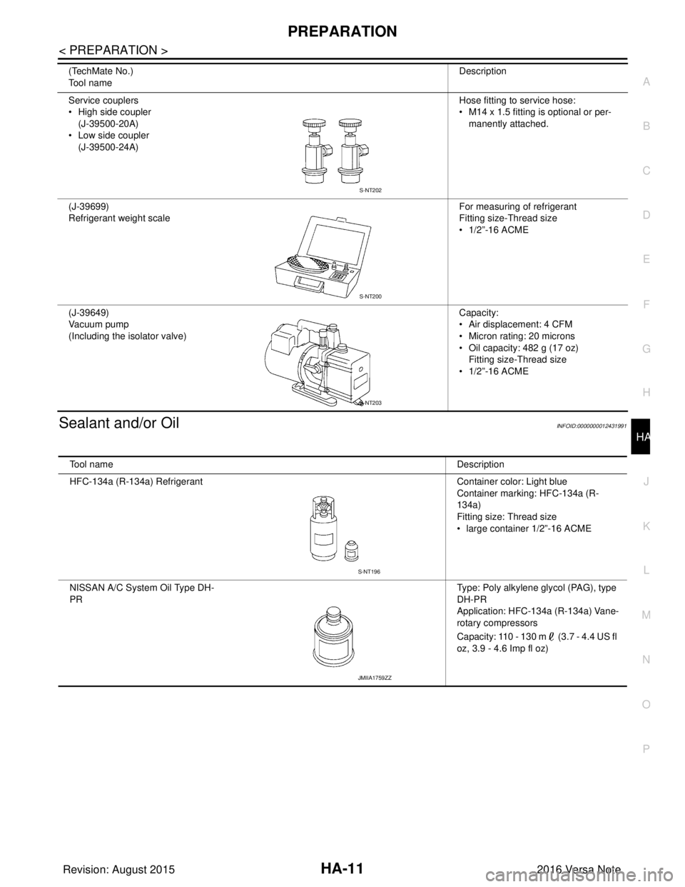
Service couplers
• High side coupler (J-39500-20A)
• Low side coupler
(J-39500-24A) Hose fitting to service hose:
• M14 x 1.5 fitting is optional or per-
manently attached.
(J-39699)
Refrigerant weight scale For measuring of refrigerant
Fitting size-Thread size
• 1/2”-16 ACME
(J-39649)
Vacuum pump
(Including the isolator valve) Capacity:
• Air displacement: 4 CFM
• Micron rating: 20 microns
• Oil capacity: 482 g (17 oz)
Fitting size-Thread size
• 1/2”-16 ACME
(TechMate No.)
Tool name
Description
S-NT202
S-NT200
S-NT203
Tool name
Description
HFC-134a (R-134a) Refrigerant Container color: Light blue
Container marking: HFC-134a (R-
134a)
Fitting size: Thread size
• large container 1/2”-16 ACME
NISSAN A/C System Oil Type DH-
PR Type: Poly alkylene glycol (PAG), type
DH-PR
Application: HFC-134a (R-134a) Vane-
rotary compressors
Capacity: 110 - 130 m (3.7 - 4.4 US fl
oz, 3.9 - 4.6 Imp fl oz)
S-NT196
JMIIA1759ZZ
Revision: August 2015
2016 Versa Note
cardiagn.com
Page 2037 of 3641
HA-12
< SYSTEM DESCRIPTION >
COMPONENT PARTS
SYSTEM DESCRIPTION
COMPONENT PARTS
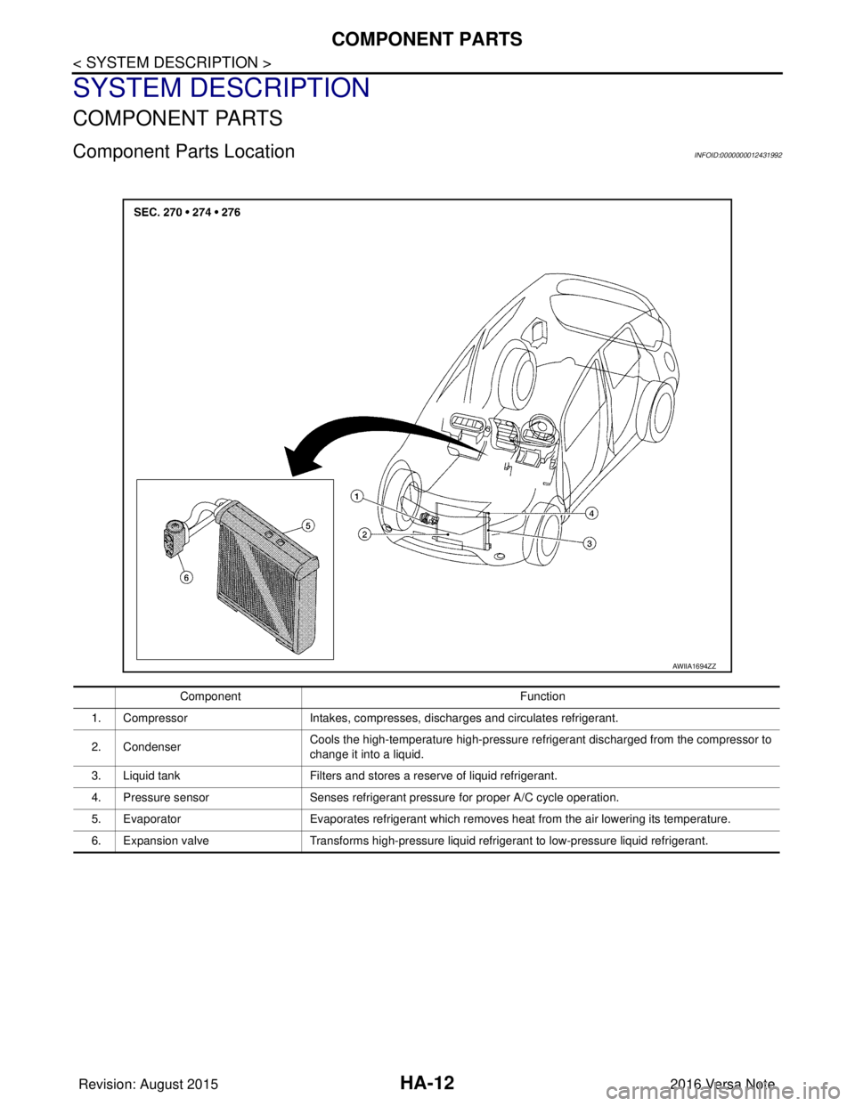
Component Parts LocationINFOID:0000000012431992
AWIIA1694ZZ
ComponentFunction
1. Compressor Intakes, compresses, discharges and circulates refrigerant.
2. Condenser Cools the high-temperature high-pressure refrigerant discharged from the compressor to
change it into a liquid.
3. Liquid tank Filters and stores a reserve of liquid refrigerant.
4. Pressure sensor Senses refrigerant pressure for proper A/C cycle operation.
5. Evaporator Evaporates refrigerant which removes heat from the air lowering its temperature.
6. Expansion valve Transforms high-pressure liquid refrigerant to low-pressure liquid refrigerant.
Revision: August 2015 2016 Versa Note
cardiagn.com
Page 2038 of 3641
DIAGNOSIS AND REPAIR WORKFLOWHA-13
< BASIC INSPECTION >
C
DE
F
G H
J
K L
M A
B
HA
N
O P
BASIC INSPECTION
DIAGNOSIS AND REPAIR WORKFLOW
WorkflowINFOID:0000000012431993
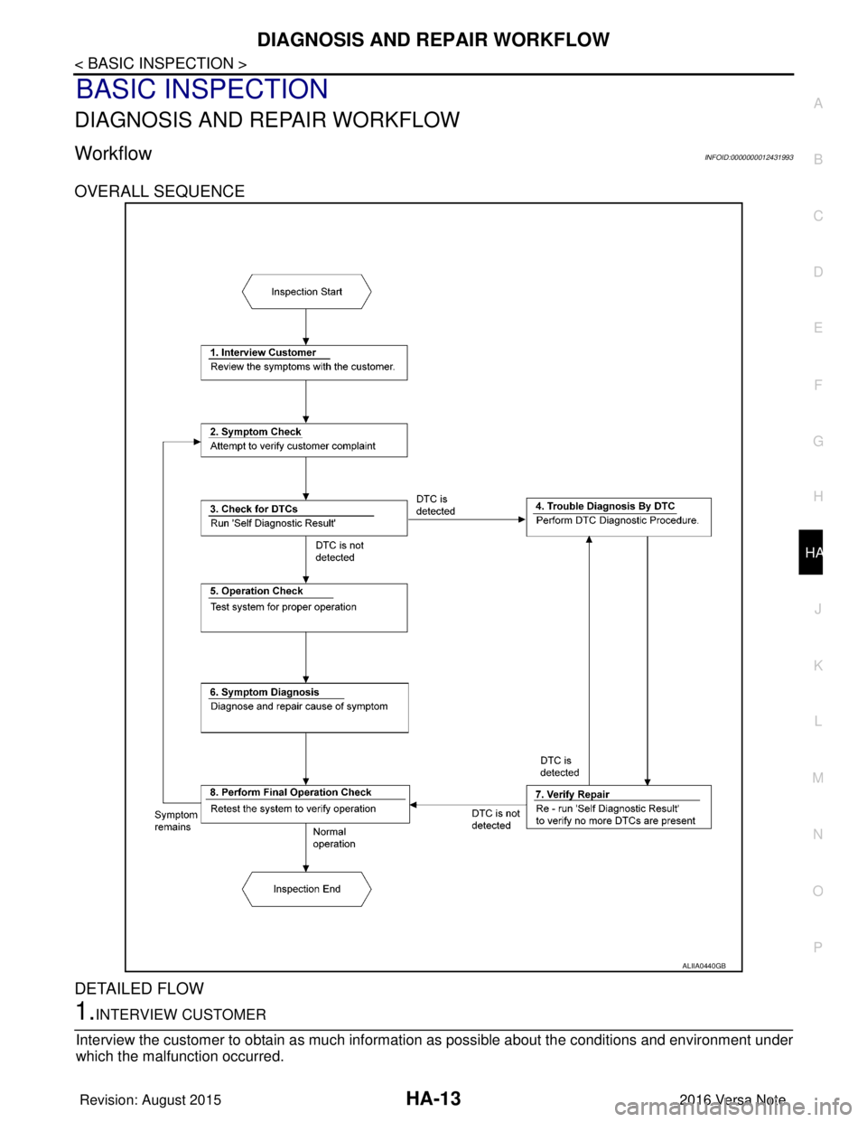
OVERALL SEQUENCE
DETAILED FLOW
1.INTERVIEW CUSTOMER
Interview the customer to obtain as much informa tion as possible about the conditions and environment under
which the malfunction occurred.
ALIIA0440GB
Revision: August 2015 2016 Versa Note
cardiagn.com
Page 2039 of 3641
HA-14
< BASIC INSPECTION >
DIAGNOSIS AND REPAIR WORKFLOW
>> GO TO 2.
2.SYMPTOM CHECK
Verify symptoms.
>> GO TO 3.
3.CHECK FOR DTCS
With CONSULT
1. Turn ignition switch ON.
2. Select “Self Diagnostic Result” of “BCM”.
3. Check DTC.
Is any DTC detected?
YES >> GO TO 4.
NO >> GO TO 5.
4.PERFORM DTC DIAGNOSTIC PROCEDURE
Perform the diagnostic procedure fo r the detected DTC. Refer to BCS-49, "
DTCInspectionPriorityChart"
(with Intelligent Key system) or BCS-115, "DTCInspectionPriorityChart" (without Intelligent Key system).
>> GO TO 7.
5.OPERATION CHECK
Perform the operation check. Refer to HAC-30, "
Work Procedure".
>> GO TO 6.
6.SYMPTOM DIAGNOSIS
Check the symptom diagnosis table. Refer to HA-15, "
Symptom Table".
>> GO TO 8.
7.VERIFY REPAIR.
With CONSULT
1. Turn ignition switch ON.
2. Select “Self Diagnostic Result” of “BCM”.
3. Check DTC.
Is any DTC detected?
YES >> GO TO 4.
NO >> GO TO 8.
8.PERFORM FINAL OPERATION CHECK
Perform the operation check. Refer to HAC-30, "
Work Procedure".
Does it operate normally?
YES >> Inspection End.
NO >> GO TO 2.
Revision: August 2015 2016 Versa Note
cardiagn.com
Page 2040 of 3641
REFRIGERATION SYSTEM SYMPTOMSHA-15
< SYMPTOM DIAGNOSIS >
C
DE
F
G H
J
K L
M A
B
HA
N
O P
SYMPTOM DIAGNOSIS
REFRIGERATION SYSTEM SYMPTOMS
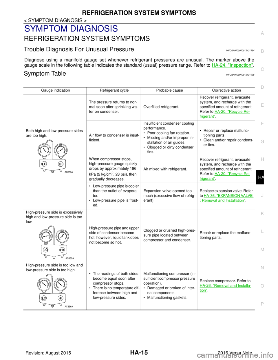
Trouble Diagnosis For Unusual PressureINFOID:0000000012431994
Diagnose using a manifold gauge set whenever refrigerant pressures are unusual. The marker above the
gauge scale in the following table indicates the standard (usual) pressure range. Refer to HA-24, "
Inspection".
Symptom TableINFOID:0000000012431995
Gauge indicationRefrigerant cycleProbable causeCorrective action
Both high and low-pressure sides
are too high. The pressure returns to nor-
mal soon after sprinkling wa-
ter on condenser.
Overfilled refrigerant. Recover refrigerant, evacuate
system, and recharge with the
specified amount of refrigerant.
Refer to HA-20, "
Recycle Re-
frigerant".
Air flow to condenser is insuf-
ficient. Insufficient condenser cooling
performance.
• Poor cooling fan rotation.
• Missing and/or improper in-
stallation of air guides.
• Clogged or dirty condenser fins. • Repair or replace malfunc-
tioning parts.
• Clean and/or repair condens- er fins.
When compressor stops,
high-pressure gauge quickly
drops by approximately 196
kPa (2 kg/cm
2, 28 psi), then
gradually decreases. Air mixed with refrigerant.
Recover refrigerant, evacuate
system, and recharge with the
specified amount of refrigerant.
Refer to HA-20, "Recycle Re-
frigerant".
• Low-pressure pipe is cooler than the outlet of evapora-
tor.
• Low-pressure pipe is frost- ed. Expansion valve opened too
much (excessive flow of refrig-
erant).
Replace expansion valve. Refer
to
HA-36, "
EXPANSION VALVE
: Removal and Installation".
High-pressure side is excessively
high and low-pressure side is too
low. High-pressure pipe and upper
side of condenser become
hot, however, liquid tank does
not become so hot.Clogged or crushed high-pres-
sure pipe located between
compressor and condenser.
Repair or replace the malfunc-
tioning parts.
High-pressure side is too low and
low-pressure side is too high. • The readings of both sides
become equal soon after
compressor stops.
• There is no temperature dif-
ference between high and
low-pressure sides. Malfunctioning compressor (in-
sufficient compressor pressure
operation).
• Damaged or broken of inter-
nal components.
• Malfunctioning gaskets. Replace compressor. Refer to
HA-26, "
Removal and Installa-
tion".
AC359A
AC360A
AC356A
Revision: August 2015
2016 Versa Note
cardiagn.com