NISSAN NOTE 2016 Service Repair Manual
Manufacturer: NISSAN, Model Year: 2016,
Model line: NOTE,
Model: NISSAN NOTE 2016
Pages: 3641, PDF Size: 28.72 MB
NISSAN NOTE 2016 Service Repair Manual
NOTE 2016
NISSAN
NISSAN
https://www.carmanualsonline.info/img/5/57363/w960_57363-0.png
NISSAN NOTE 2016 Service Repair Manual
Trending: RADIO SET UP, center console, jacking, checking oil, display, bolt pattern, timing belt
Page 3621 of 3641
WW-56
< REMOVAL AND INSTALLATION >
WASHER TANK
REMOVAL AND INSTALLATION
WASHER TANK
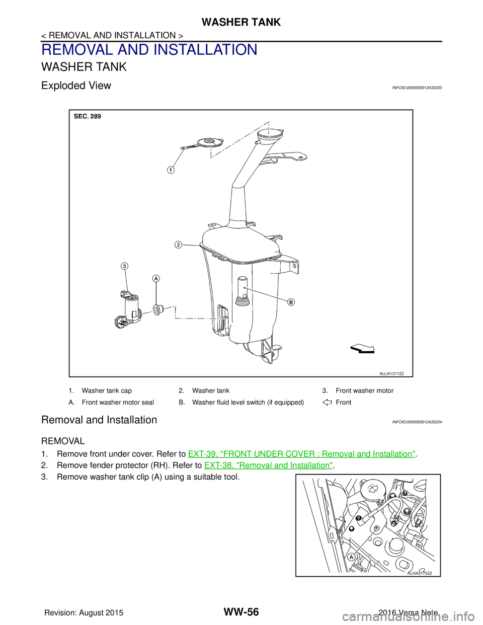
Exploded ViewINFOID:0000000012433233
Removal and InstallationINFOID:0000000012433234
REMOVAL
1. Remove front under cover. Refer to EXT-39, "FRONT UNDER COVER : Removal and Installation".
2. Remove fender protector (RH). Refer to EXT-38, "
Removal and Installation".
3. Remove washer tank clip (A) using a suitable tool.
1. Washer tank cap 2. Washer tank 3. Front washer motor
A. Front washer motor seal B. Washer fluid level switch (if equipped) Front
ALLIA1317ZZ
ALKIA3175ZZ
Revision: August 2015 2016 Versa Note
cardiagn.com
Page 3622 of 3641
WASHER TANKWW-57
< REMOVAL AND INSTALLATION >
C
DE
F
G H
I
J
K
M A
B
WW
N
O P
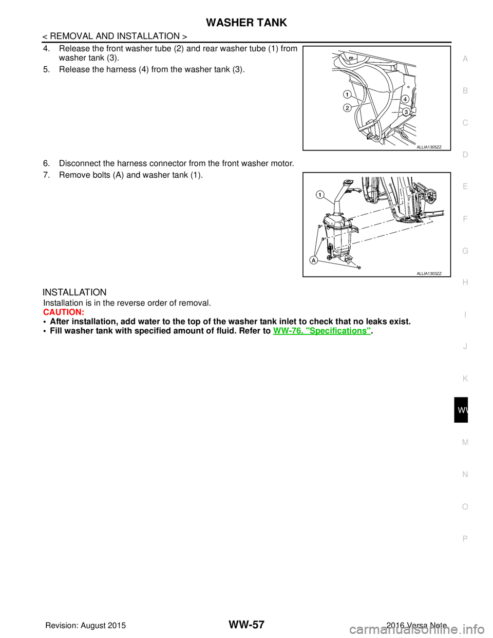
4. Release the front washer tube (2) and rear washer tube (1) from
washer tank (3).
5. Release the harness (4) from the washer tank (3).
6. Disconnect the harness connector from the front washer motor.
7. Remove bolts (A) and washer tank (1).
INSTALLATION
Installation is in the reverse order of removal.
CAUTION:
• After installation, add water to the top of th e washer tank inlet to check that no leaks exist.
• Fill washer tank with specified amount of fluid. Refer to WW-76, "
Specifications".
ALLIA1305ZZ
ALLIA1303ZZ
Revision: August 2015 2016 Versa Note
cardiagn.com
Page 3623 of 3641
WW-58
< REMOVAL AND INSTALLATION >
FRONT WASHER MOTOR
FRONT WASHER MOTOR
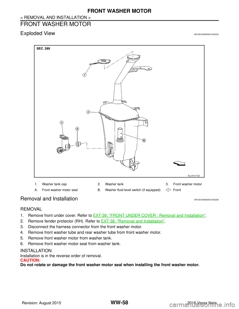
Exploded ViewINFOID:0000000012433235
Removal and InstallationINFOID:0000000012433236
REMOVAL
1. Remove front under cover. Refer to EXT-39, "FRONT UNDER COVER : Removal and Installation".
2. Remove fender protector (RH). Refer to EXT-38, "
Removal and Installation".
3. Disconnect the harness connector from the front washer motor.
4. Remove front washer tube and rear wa sher tube from front washer motor.
5. Remove front washer motor from washer tank.
6. Remove front washer motor seal from washer tank.
INSTALLATION
Installation is in the reverse order of removal.
CAUTION:
Do not rotate or damage the front washer moto r seal when installing the front washer motor.
1. Washer tank cap 2. Washer tank 3. Front washer motor
A. Front washer motor seal B. Washer fluid level switch (if equipped) Front
ALLIA1317ZZ
Revision: August 2015 2016 Versa Note
cardiagn.com
Page 3624 of 3641
WASHER FLUID LEVEL SWITCHWW-59
< REMOVAL AND INSTALLATION >
C
DE
F
G H
I
J
K
M A
B
WW
N
O P
WASHER FLUID LEVEL SWITCH
Removal and InstallationINFOID:0000000012433237
The washer fluid level switch is serviced as part of the washer tank. Refer to WW-56, "Removal and Installa-
tion".
Revision: August 2015 2016 Versa Note
cardiagn.com
Page 3625 of 3641
WW-60
< REMOVAL AND INSTALLATION >
FRONT WASHER NOZZLE AND TUBE
FRONT WASHER NOZZLE AND TUBE
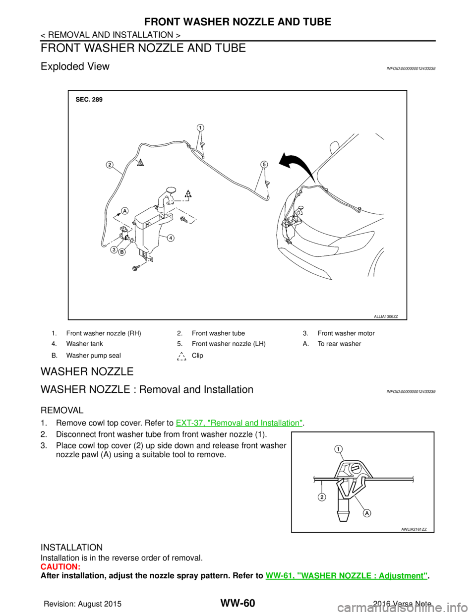
Exploded ViewINFOID:0000000012433238
WASHER NOZZLE
WASHER NOZZLE : Removal and InstallationINFOID:0000000012433239
REMOVAL
1. Remove cowl top cover. Refer to EXT-37, "Removal and Installation".
2. Disconnect front washer tube fr om front washer nozzle (1).
3. Place cowl top cover (2) up side down and release front washer nozzle pawl (A) using a suitable tool to remove.
INSTALLATION
Installation is in the reverse order of removal.
CAUTION:
After installation, adjust the nozzle spray pattern. Refer to WW-61, "
WASHER NOZZLE : Adjustment".
1. Front washer nozzle (RH) 2. Front washer tube3. Front washer motor
4. Washer tank 5. Front washer nozzle (LH) A. To rear washer
B. Washer pump seal Clip
ALLIA1306ZZ
AWLIA2161ZZ
Revision: August 2015 2016 Versa Note
cardiagn.com
Page 3626 of 3641
FRONT WASHER NOZZLE AND TUBEWW-61
< REMOVAL AND INSTALLATION >
C
DE
F
G H
I
J
K
M A
B
WW
N
O P
WASHER NOZZLE : AdjustmentINFOID:0000000012433240
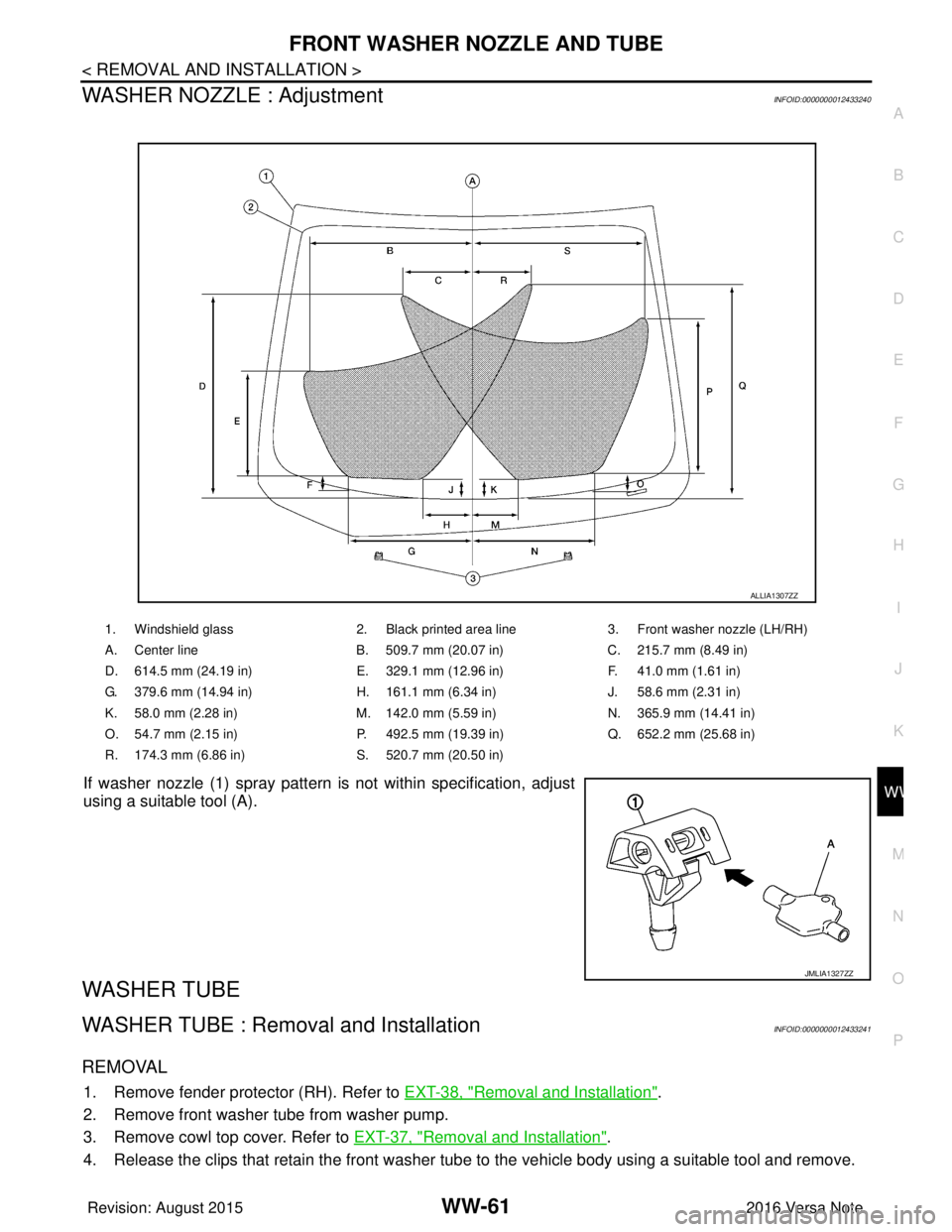
If washer nozzle (1) spray pattern is not within specification, adjust
using a suitable tool (A).
WASHER TUBE
WASHER TUBE : Removal and InstallationINFOID:0000000012433241
REMOVAL
1. Remove fender protector (RH). Refer to EXT-38, "Removal and Installation".
2. Remove front washer tube from washer pump.
3. Remove cowl top cover. Refer to EXT-37, "
Removal and Installation".
4. Release the clips that retain the front washer tube to the vehicle body using a suitable tool and remove.
1. Windshield glass 2. Black printed area line3. Front washer nozzle (LH/RH)
A. Center line B. 509.7 mm (20.07 in)C. 215.7 mm (8.49 in)
D. 614.5 mm (24.19 in) E. 329.1 mm (12.96 in)F. 41.0 mm (1.61 in)
G. 379.6 mm (14.94 in) H. 161.1 mm (6.34 in)J. 58.6 mm (2.31 in)
K. 58.0 mm (2.28 in) M. 142.0 mm (5.59 in)N. 365.9 mm (14.41 in)
O. 54.7 mm (2.15 in) P. 492.5 mm (19.39 in)Q. 652.2 mm (25.68 in)
R. 174.3 mm (6.86 in) S. 520.7 mm (20.50 in)
ALLIA1307ZZ
JMLIA1327ZZ
Revision: August 2015 2016 Versa Note
cardiagn.com
Page 3627 of 3641
WW-62
< REMOVAL AND INSTALLATION >
FRONT WASHER NOZZLE AND TUBE
INSTALLATION
Installation is in the reverse order of removal.
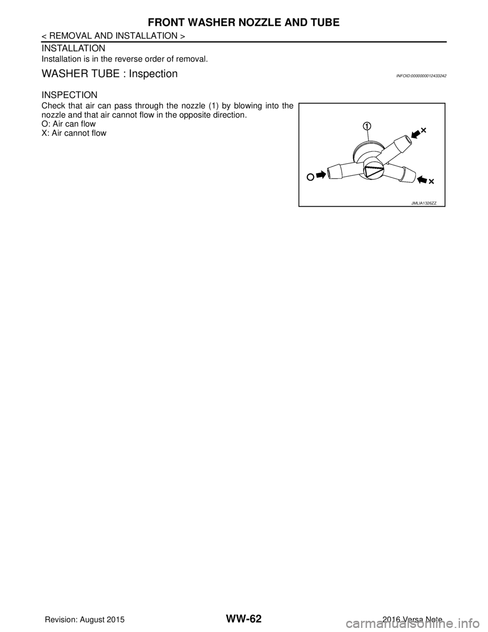
WASHER TUBE : InspectionINFOID:0000000012433242
INSPECTION
Check that air can pass through the nozzle (1) by blowing into the
nozzle and that air cannot flow in the opposite direction.
O: Air can flow
X: Air cannot flow
JMLIA1326ZZ
Revision: August 20152016 Versa Note
cardiagn.com
Page 3628 of 3641
FRONT WIPER ARMWW-63
< REMOVAL AND INSTALLATION >
C
DE
F
G H
I
J
K
M A
B
WW
N
O P
FRONT WIPER ARM
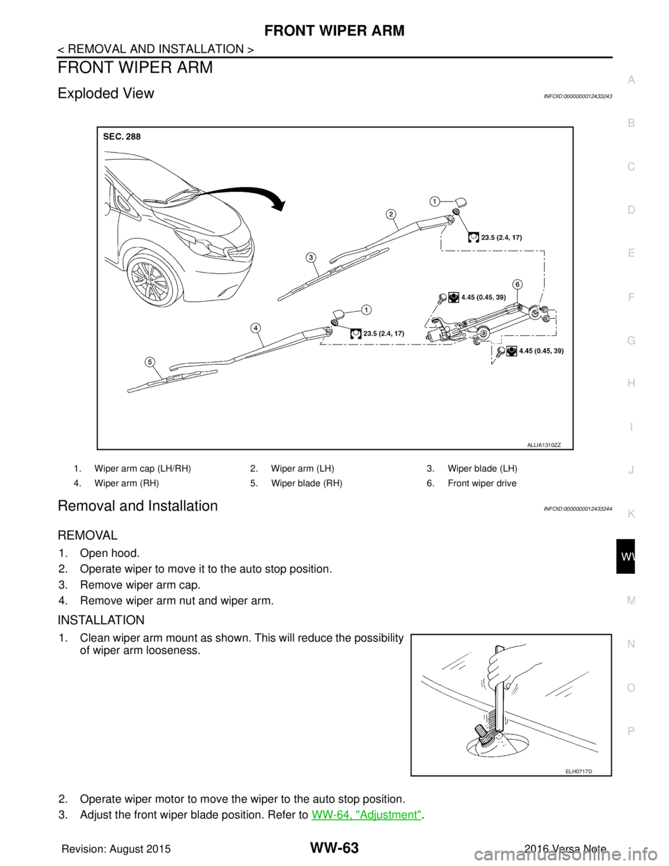
Exploded ViewINFOID:0000000012433243
Removal and InstallationINFOID:0000000012433244
REMOVAL
1. Open hood.
2. Operate wiper to move it to the auto stop position.
3. Remove wiper arm cap.
4. Remove wiper arm nut and wiper arm.
INSTALLATION
1. Clean wiper arm mount as shown. This will reduce the possibility of wiper arm looseness.
2. Operate wiper motor to move the wiper to the auto stop position.
3. Adjust the front wiper blade position. Refer to WW-64, "
Adjustment".
1. Wiper arm cap (LH/RH)2. Wiper arm (LH)3. Wiper blade (LH)
4. Wiper arm (RH) 5. Wiper blade (RH)6. Front wiper drive
ALLIA1310ZZ
ELH0717D
Revision: August 2015 2016 Versa Note
cardiagn.com
Page 3629 of 3641
WW-64
< REMOVAL AND INSTALLATION >
FRONT WIPER ARM
4. Install front wiper arm and front wiper arm nut.CAUTION:
Tighten front wiper arm nut to specification. Refer to WW-63, "
Exploded View".
5. Install front wiper arm cap.
6. Check that wiper blades stop at the specified position. Refer to WW-64, "
Adjustment".
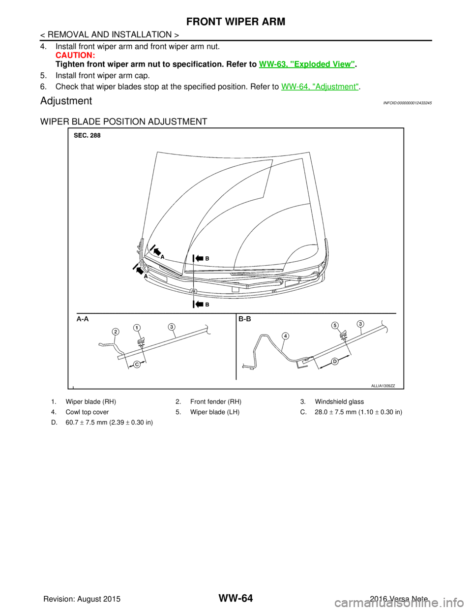
AdjustmentINFOID:0000000012433245
WIPER BLADE POSITION ADJUSTMENT
ALLIA1309ZZ
1. Wiper blade (RH) 2. Front fender (RH) 3. Windshield glass
4. Cowl top cover 5. Wiper blade (LH) C. 28.0 ± 7.5 mm (1.10 ± 0.30 in)
D. 60.7 ± 7.5 mm (2.39 ± 0.30 in)
Revision: August 2015 2016 Versa Note
cardiagn.com
Page 3630 of 3641
FRONT WIPER BLADEWW-65
< REMOVAL AND INSTALLATION >
C
DE
F
G H
I
J
K
M A
B
WW
N
O P
FRONT WIPER BLADE
Removal and InstallationINFOID:0000000012433246
REMOVAL
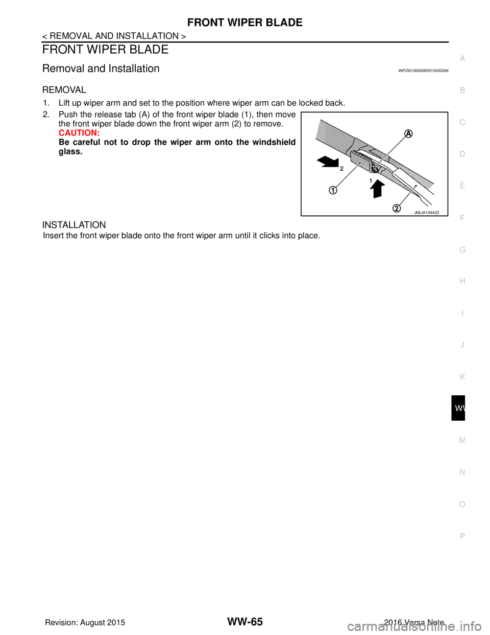
1. Lift up wiper arm and set to the position where wiper arm can be locked back.
2. Push the release tab (A) of the front wiper blade (1), then move the front wiper blade down the front wiper arm (2) to remove.
CAUTION:
Be careful not to drop the wiper arm onto the windshield
glass.
INSTALLATION
Insert the front wiper blade onto the front wiper arm until it clicks into place.
JMLIA1044ZZ
Revision: August 2015 2016 Versa Note
cardiagn.com
Trending: Wiper, display, fuel tank removal, RE0F11A, ign relay, fuel, trailer
