NISSAN NOTE 2016 Service Repair Manual
Manufacturer: NISSAN, Model Year: 2016, Model line: NOTE, Model: NISSAN NOTE 2016Pages: 3641, PDF Size: 28.72 MB
Page 3601 of 3641
WW-36
< DTC/CIRCUIT DIAGNOSIS >
FRONT WIPER MOTOR LO CIRCUIT
FRONT WIPER MOTOR LO CIRCUIT
Component Function CheckINFOID:0000000012433215
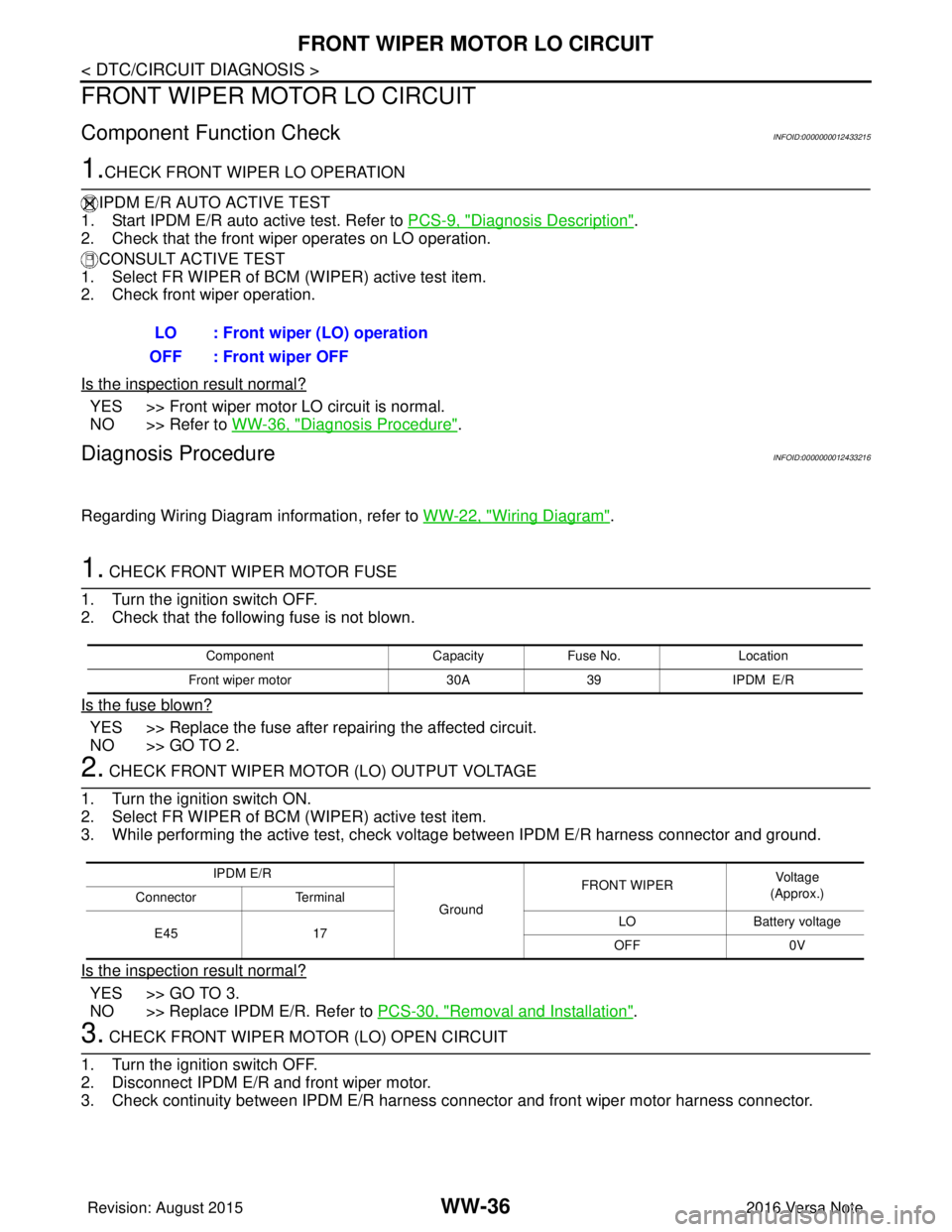
1.CHECK FRONT WIPER LO OPERATION
IPDM E/R AUTO ACTIVE TEST
1. Start IPDM E/R auto active test. Refer to PCS-9, "
Diagnosis Description".
2. Check that the front wiper operates on LO operation.
CONSULT ACTIVE TEST
1. Select FR WIPER of BCM (WIPER) active test item.
2. Check front wiper operation.
Is the inspection result normal?
YES >> Front wiper motor LO circuit is normal.
NO >> Refer to WW-36, "
Diagnosis Procedure".
Diagnosis ProcedureINFOID:0000000012433216
Regarding Wiring Diagram information, refer to WW-22, "Wiring Diagram".
1. CHECK FRONT WIPER MOTOR FUSE
1. Turn the ignition switch OFF.
2. Check that the following fuse is not blown.
Is the fuse blown?
YES >> Replace the fuse after repairing the affected circuit.
NO >> GO TO 2.
2. CHECK FRONT WIPER MOTOR (LO) OUTPUT VOLTAGE
1. Turn the ignition switch ON.
2. Select FR WIPER of BCM (WIPER) active test item.
3. While performing the active test, check vo ltage between IPDM E/R harness connector and ground.
Is the inspection result normal?
YES >> GO TO 3.
NO >> Replace IPDM E/R. Refer to PCS-30, "
Removal and Installation".
3. CHECK FRONT WIPER MOTOR (LO) OPEN CIRCUIT
1. Turn the ignition switch OFF.
2. Disconnect IPDM E/R and front wiper motor.
3. Check continuity between IPDM E/R harness connector and front wiper motor harness connector.
LO : Front wiper (LO) operation
OFF : Front wiper OFF
Component CapacityFuse No. Location
Front wiper motor 30A39 IPDM E/R
IPDM E/R
GroundFRONT WIPER
Vo l ta g e
(Approx.)
Connector Terminal
E45 17 LO
Battery voltage
OFF 0V
Revision: August 2015 2016 Versa Note
cardiagn.com
Page 3602 of 3641

FRONT WIPER MOTOR LO CIRCUITWW-37
< DTC/CIRCUIT DIAGNOSIS >
C
DE
F
G H
I
J
K
M A
B
WW
N
O P
Is the inspection result normal?
YES >> Replace front wiper motor. Refer to WW-66, "Removal and Installation".
NO >> Repair or replace harness.
IPDM E/R Front wiper motor
Continuity
Connector TerminalConnector Terminal
E45 17E1 3Yes
Revision: August 2015 2016 Versa Note
cardiagn.com
Page 3603 of 3641
WW-38
< DTC/CIRCUIT DIAGNOSIS >
FRONT WIPER MOTOR HI CIRCUIT
FRONT WIPER MOTOR HI CIRCUIT
Component Function CheckINFOID:0000000012433217
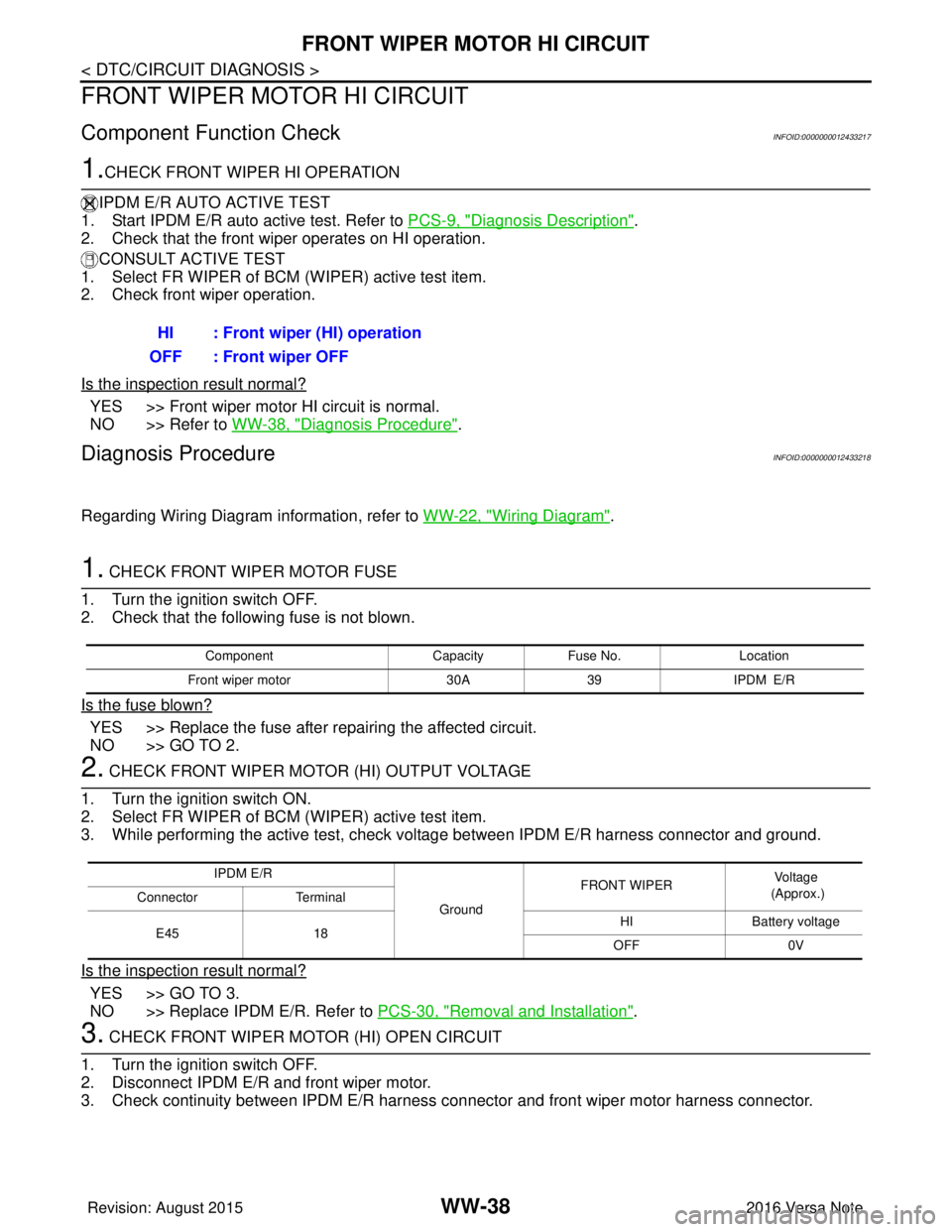
1.CHECK FRONT WIPER HI OPERATION
IPDM E/R AUTO ACTIVE TEST
1. Start IPDM E/R auto active test. Refer to PCS-9, "
Diagnosis Description".
2. Check that the front wiper operates on HI operation.
CONSULT ACTIVE TEST
1. Select FR WIPER of BCM (WIPER) active test item.
2. Check front wiper operation.
Is the inspection result normal?
YES >> Front wiper motor HI circuit is normal.
NO >> Refer to WW-38, "
Diagnosis Procedure".
Diagnosis ProcedureINFOID:0000000012433218
Regarding Wiring Diagram information, refer to WW-22, "Wiring Diagram".
1. CHECK FRONT WIPER MOTOR FUSE
1. Turn the ignition switch OFF.
2. Check that the following fuse is not blown.
Is the fuse blown?
YES >> Replace the fuse after repairing the affected circuit.
NO >> GO TO 2.
2. CHECK FRONT WIPER MOTOR (HI) OUTPUT VOLTAGE
1. Turn the ignition switch ON.
2. Select FR WIPER of BCM (WIPER) active test item.
3. While performing the active test, check vo ltage between IPDM E/R harness connector and ground.
Is the inspection result normal?
YES >> GO TO 3.
NO >> Replace IPDM E/R. Refer to PCS-30, "
Removal and Installation".
3. CHECK FRONT WIPER MOTOR (HI) OPEN CIRCUIT
1. Turn the ignition switch OFF.
2. Disconnect IPDM E/R and front wiper motor.
3. Check continuity between IPDM E/R harness connector and front wiper motor harness connector.
HI : Front wiper (HI) operation
OFF : Front wiper OFF
Component CapacityFuse No. Location
Front wiper motor 30A39 IPDM E/R
IPDM E/R
GroundFRONT WIPER
Voltage
(Approx.)
Connector Terminal
E45 18 HI
Battery voltage
OFF 0V
Revision: August 2015 2016 Versa Note
cardiagn.com
Page 3604 of 3641

FRONT WIPER MOTOR HI CIRCUITWW-39
< DTC/CIRCUIT DIAGNOSIS >
C
DE
F
G H
I
J
K
M A
B
WW
N
O P
Is the inspection result normal?
YES >> Replace front wiper motor. Refer to WW-66, "Removal and Installation".
NO >> Repair or replace harness.
IPDM E/R Front wiper motor
Continuity
Connector TerminalConnector Terminal
E45 18E1 5Yes
Revision: August 2015 2016 Versa Note
cardiagn.com
Page 3605 of 3641

WW-40
< DTC/CIRCUIT DIAGNOSIS >
FRONT WIPER AUTO STOP SIGNAL CIRCUIT
FRONT WIPER AUTO STOP SIGNAL CIRCUIT
Component Function CheckINFOID:0000000012433219
1. CHECK FRONT WIPER (AUTO STOP) SIGNAL
1. Select FR WIPER STOP of BCM (WIPER) data monitor item.
2. Operate the front wiper.
3. Check that FR WIPER STOP changes from ON to OFF according to the wiper position.
Is the inspection result normal?
YES >> Front wiper auto stop signal circuit is normal.
NO >> Refer to WW-40, "
Diagnosis Procedure".
Diagnosis ProcedureINFOID:0000000012433220
Regarding Wiring Diagram information, refer to WW-22, "Wiring Diagram".
1. CHECK FRONT WIPER MOTOR (AUTO STOP) OUTPUT VOLTAGE
1. Turn the ignition switch ON.
2. Check voltage between IPDM E/R harness connector and ground.
Is the inspection result normal?
YES >> Check for intermittent failure.
NO >> GO TO 2.
2. CHECK FRONT WIPER MOTOR (AUTO STOP) SHORT CIRCUIT
1. Turn the ignition switch OFF.
2. Disconnect IPDM E/R and front wiper motor.
3. Check continuity between IP DM E/R harness connector and ground.
Is the inspection result normal?
YES >> GO TO 3.
NO >> Repair or replace harness.
3. CHECK FRONT WIPER MOTOR (AUTO STOP) CIRCUIT CONTINUITY
Check continuity between IPDM E/R harness c onnector and front wiper motor harness connector.
Is the inspection result normal?
Data monitor ConditionStatus
FR WIPER STOP Front wiper motor Stop position
ON
Except stop position OFF
IPDM E/R
GroundFRONT WIPER
Vo l ta g e
(Approx.)
Connector Terminal
E46 74 Except stop position
Battery voltage
Stop position 0 V
IPDM E/R
GroundContinuity
Connector Terminal
E46 74 No
IPDM E/R Front wiper motor
Continuity
Connector TerminalConnector Terminal
E46 74E1 4Yes
Revision: August 2015 2016 Versa Note
cardiagn.com
Page 3606 of 3641

FRONT WIPER AUTO STOP SIGNAL CIRCUITWW-41
< DTC/CIRCUIT DIAGNOSIS >
C
DE
F
G H
I
J
K
M A
B
WW
N
O P
YES >> Replace front wiper motor. Refer to WW-66, "Removal and Installation".
NO >> Repair or replace harness.
Revision: August 2015 2016 Versa Note
cardiagn.com
Page 3607 of 3641

WW-42
< DTC/CIRCUIT DIAGNOSIS >
FRONT WIPER MOTOR GROUND CIRCUIT
FRONT WIPER MOTOR GROUND CIRCUIT
Diagnosis ProcedureINFOID:0000000012433221
Regarding Wiring Diagram information, refer to WW-22, "Wiring Diagram".
1. CHECK FRONT WIPER MOTOR GROUND CIRCUIT
1. Turn the ignition switch OFF.
2. Disconnect front wiper motor.
3. Check continuity between front wiper motor harness connector and ground.
Is the inspection result normal?
YES >> Front wiper motor ground circuit is normal.
NO >> Repair or replace harness.
Front wiper motor
GroundContinuity
Connector Terminal
E1 2 Yes
Revision: August 2015 2016 Versa Note
cardiagn.com
Page 3608 of 3641
WASHER MOTOR CIRCUITWW-43
< DTC/CIRCUIT DIAGNOSIS >
C
DE
F
G H
I
J
K
M A
B
WW
N
O P
WASHER MOTOR CIRCUIT
Diagnosis ProcedureINFOID:0000000012433222
Regarding Wiring Diagram information, refer to WW-22, "Wiring Diagram", WW-28, "Wiring Diagram".
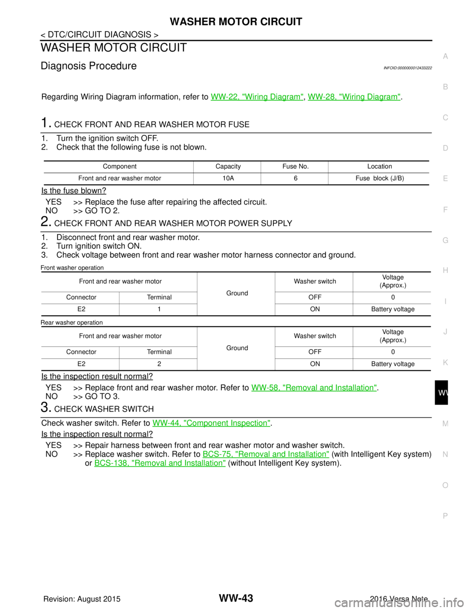
1. CHECK FRONT AND REAR WASHER MOTOR FUSE
1. Turn the ignition switch OFF.
2. Check that the following fuse is not blown.
Is the fuse blown?
YES >> Replace the fuse after repairing the affected circuit.
NO >> GO TO 2.
2. CHECK FRONT AND REAR WASHER MOTOR POWER SUPPLY
1. Disconnect front and rear washer motor.
2. Turn ignition switch ON.
3. Check voltage between front and rear washer motor harness connector and ground.
Front washer operation
Rear washer operation
Is the inspection result normal?
YES >> Replace front and rear washer motor. Refer to WW-58, "Removal and Installation".
NO >> GO TO 3.
3. CHECK WASHER SWITCH
Check washer switch. Refer to WW-44, "
Component Inspection".
Is the inspection result normal?
YES >> Repair harness between front and rear washer motor and washer switch.
NO >> Replace washer switch. Refer to BCS-75, "
Removal and Installation" (with Intelligent Key system)
or BCS-138, "
Removal and Installation" (without Intelligent Key system).
Component CapacityFuse No. Location
Front and rear washer motor 10A6Fuse block (J/B)
Front and rear washer motor
GroundWasher switch
Voltage
(Approx.)
Connector Terminal OFF0
E2 1 ONBattery voltage
Front and rear washer motor GroundWasher switch
Voltage
(Approx.)
Connector Terminal OFF0
E2 2 ONBattery voltage
Revision: August 2015 2016 Versa Note
cardiagn.com
Page 3609 of 3641
WW-44
< DTC/CIRCUIT DIAGNOSIS >
WASHER SWITCH
WASHER SWITCH
DescriptionINFOID:0000000012433223
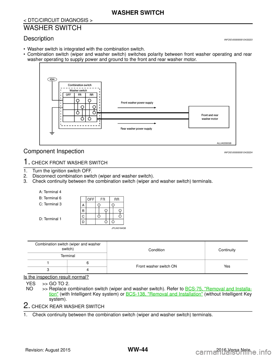
• Washer switch is integrated with the combination switch.
• Combination switch (wiper and washer switch) switches polarity between front washer operating and rear
washer operating to supply power and ground to the front and rear washer motor.
Component InspectionINFOID:0000000012433224
1. CHECK FRONT WASHER SWITCH
1. Turn the ignition switch OFF.
2. Disconnect combination switch (wiper and washer switch).
3. Check continuity between the combination switch (wiper and washer switch) terminals.
Is the inspection result normal?
YES >> GO TO 2.
NO >> Replace combination switch (wiper and washer switch). Refer to BCS-75, "
Removal and Installa-
tion" (with Intelligent Key system) or BCS-138, "Removal and Installation" (without Intelligent Key
system).
2. CHECK REAR WASHER SWITCH
1. Check continuity between the combination switch (wiper and washer switch) terminals.
ALLIA0350GB
A: Terminal 4
B: Terminal 6
C: Terminal 3
D: Terminal 1
JPLIA0164GB
Combination switch (wiper and washer
switch) Condition Continuity
Terminal
16 Front washer switch ONYes
34
Revision: August 2015 2016 Versa Note
cardiagn.com
Page 3610 of 3641
WASHER SWITCHWW-45
< DTC/CIRCUIT DIAGNOSIS >
C
DE
F
G H
I
J
K
M A
B
WW
N
O P
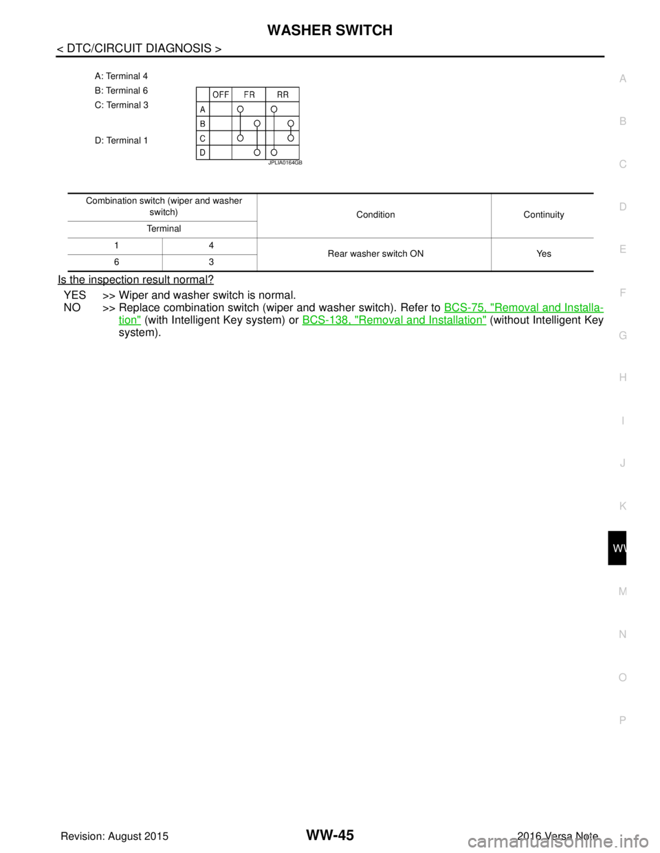
Is the inspection result normal?
YES >> Wiper and washer switch is normal.
NO >> Replace combination switch (wiper and washer switch). Refer to BCS-75, "
Removal and Installa-
tion" (with Intelligent Key system) or BCS-138, "Removal and Installation" (without Intelligent Key
system).
A: Terminal 4
B: Terminal 6
C: Terminal 3
D: Terminal 1
JPLIA0164GB
Combination switch (wiper and washer
switch) ConditionContinuity
Te r m i n a l
14 Rear washer switch ONYes
63
Revision: August 2015 2016 Versa Note
cardiagn.com