NISSAN NOTE 2016 Service Repair Manual
Manufacturer: NISSAN, Model Year: 2016, Model line: NOTE, Model: NISSAN NOTE 2016Pages: 3641, PDF Size: 28.72 MB
Page 671 of 3641
DEF-20
< DTC/CIRCUIT DIAGNOSIS >
REAR WINDOW DEFOGGER SWITCH
DTC/CIRCUIT DIAGNOSIS
REAR WINDOW DEFOGGER SWITCH
DescriptionINFOID:0000000012431763
• The rear window defogger is operated by pressing the rear window defogger switch ON.
• The indicator lamp in the rear window defogger switch illuminates while the rear window defogger is ON.
Component Function CheckINFOID:0000000012431764
1. CHECK REAR WINDOW DEFOGGER SWITCH FUNCTION
1. Turn ignition switch ON.
2. Check that the indicator lamp of rear window def ogger illuminates with rear window defogger switch ON.
Is the inspection result normal?
YES >> GO TO 2.
NO >> Refer to DEF-20, "
Diagnosis Procedure".
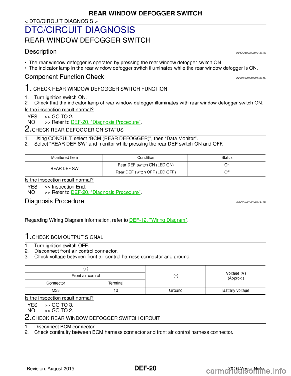
2.CHECK REAR DEFOGGER ON STATUS
1. Using CONSULT, select “BCM (REAR DEFOGGER)”, then “Data Monitor”.
2. Select “REAR DEF SW” and monitor while pressing the rear DEF switch ON and OFF.
Is the inspection result normal?
YES >> Inspection End.
NO >> Refer to DEF-20, "
Diagnosis Procedure".
Diagnosis ProcedureINFOID:0000000012431765
Regarding Wiring Diagram information, refer to DEF-12, "Wiring Diagram".
1.CHECK BCM OUTPUT SIGNAL
1. Turn ignition switch OFF.
2. Disconnect front air control connector.
3. Check voltage between front air control harness connector and ground.
Is the inspection result normal?
YES >> GO TO 3.
NO >> GO TO 2.
2.CHECK REAR WINDOW DEFOGGER SWITCH CIRCUIT
1. Disconnect BCM connector.
2. Check continuity between BCM harness connec tor and front air control harness connector.
Monitored ItemConditionStatus
REAR DEF SW Rear DEF switch ON (LED ON)
On
Rear DEF switch OFF (LED OFF) Off
(+)
(–)Voltage (V)
(Approx.)
Front air control
Connector Terminal
M33 10GroundBattery voltage
Revision: August 2015 2016 Versa Note
cardiagn.com
Page 672 of 3641
REAR WINDOW DEFOGGER SWITCHDEF-21
< DTC/CIRCUIT DIAGNOSIS >
C
DE
F
G H
I
J
K
M A
B
DEF
N
O P
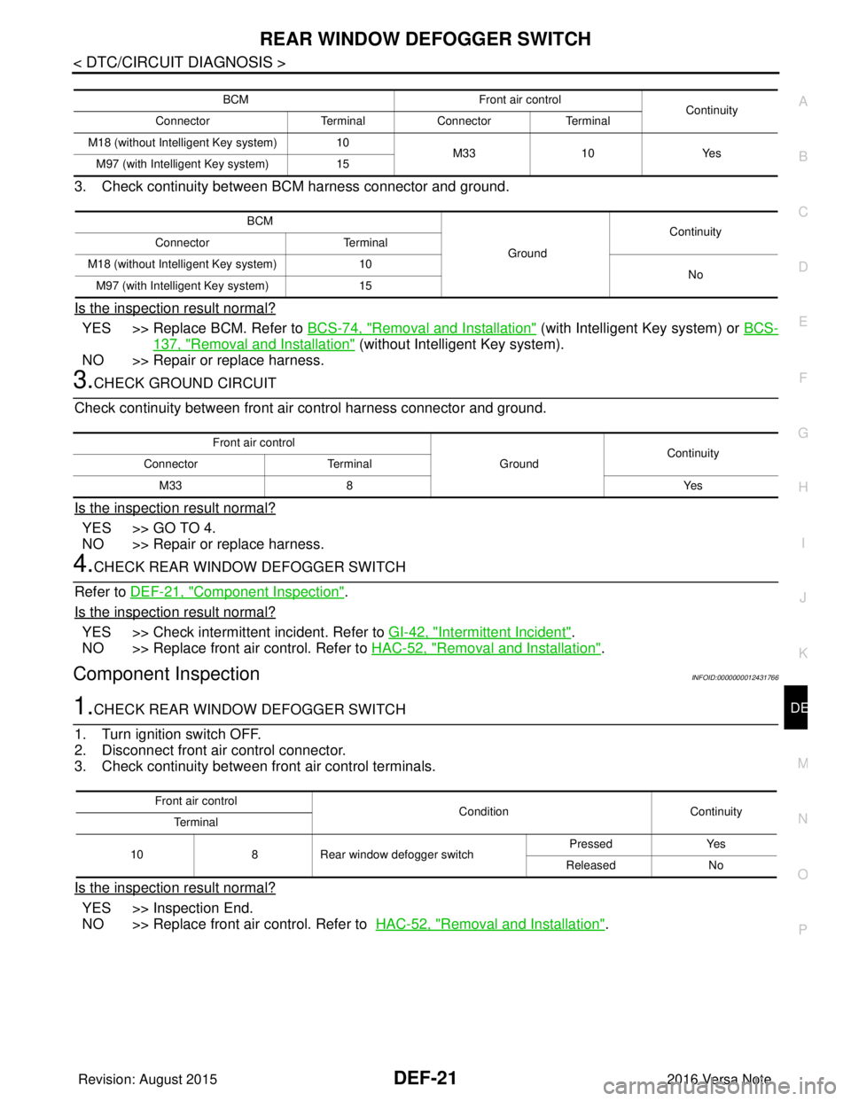
3. Check continuity between BCM harness connector and ground.
Is the inspection result normal?
YES >> Replace BCM. Refer to BCS-74, "Removal and Installation" (with Intelligent Key system) or BCS-
137, "Removal and Installation" (without Intelligent Key system).
NO >> Repair or replace harness.
3.CHECK GROUND CIRCUIT
Check continuity between front air control harness connector and ground.
Is the inspection result normal?
YES >> GO TO 4.
NO >> Repair or replace harness.
4.CHECK REAR WINDOW DEFOGGER SWITCH
Refer to DEF-21, "
Component Inspection".
Is the inspection result normal?
YES >> Check intermittent incident. Refer to GI-42, "Intermittent Incident".
NO >> Replace front air control. Refer to HAC-52, "
Removal and Installation".
Component InspectionINFOID:0000000012431766
1.CHECK REAR WINDOW DEFOGGER SWITCH
1. Turn ignition switch OFF.
2. Disconnect front air control connector.
3. Check continuity between front air control terminals.
Is the inspection result normal?
YES >> Inspection End.
NO >> Replace front air control. Refer to HAC-52, "
Removal and Installation".
BCM Front air control
Continuity
Connector TerminalConnector Terminal
M18 (without Intelligent Key system) 10
M33 10Yes
M97 (with Intelligent Key system) 15
BCM
GroundContinuity
Connector Terminal
M18 (without Intelligent Key system) 10
No
M97 (with Intelligent Key system) 15
Front air control
GroundContinuity
Connector Terminal
M33 8 Yes
Front air control
ConditionContinuity
Te r m i n a l
10 8Rear window defogger switch Pressed
Yes
Released No
Revision: August 2015 2016 Versa Note
cardiagn.com
Page 673 of 3641
DEF-22
< DTC/CIRCUIT DIAGNOSIS >
REAR WINDOW DEFOGGER RELAY
REAR WINDOW DEFOGGER RELAY
DescriptionINFOID:0000000012431767
Power is supplied to the rear window defogger with BCM control.
Component Function CheckINFOID:0000000012431768
1.CHECK FUNCTION
1. Turn ignition switch ON.
2. Check that an operation noise of rear window defogger relay can be heard when turning the rear window defogger switch ON.
Is the inspection result normal?
YES >> Rear window defogger relay function is OK.
NO >> Refer to DEF-22, "
Diagnosis Procedure"
Diagnosis ProcedureINFOID:0000000012431769
Regarding Wiring Diagram information, refer to DEF-12, "Wiring Diagram".
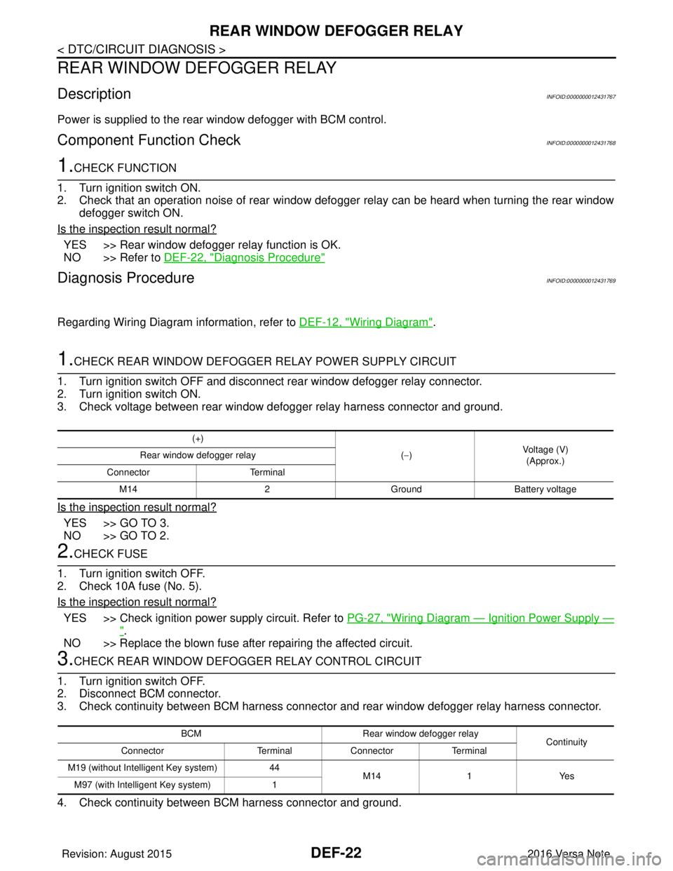
1.CHECK REAR WINDOW DEFOGGER RELAY POWER SUPPLY CIRCUIT
1. Turn ignition switch OFF and disconnect rear window defogger relay connector.
2. Turn ignition switch ON.
3. Check voltage between rear window defogger relay harness connector and ground.
Is the inspection result normal?
YES >> GO TO 3.
NO >> GO TO 2.
2.CHECK FUSE
1. Turn ignition switch OFF.
2. Check 10A fuse (No. 5).
Is the inspection result normal?
YES >> Check ignition power supply circuit. Refer to PG-27, "Wiring Diagram — Ignition Power Supply —
".
NO >> Replace the blown fuse after repairing the affected circuit.
3.CHECK REAR WINDOW DEFOGGER RELAY CONTROL CIRCUIT
1. Turn ignition switch OFF.
2. Disconnect BCM connector.
3. Check continuity between BCM harness connector and rear window defogger relay harness connector.
4. Check continuity between BCM harness connector and ground.
(+)
(−) Voltage (V)
(Approx.)
Rear window defogger relay
Connector Terminal
M14 2GroundBattery voltage
BCM Rear window defogger relay
Continuity
Connector TerminalConnector Terminal
M19 (without Intelligent Key system) 44
M14 1Yes
M97 (with Intelligent Key system) 1
Revision: August 2015 2016 Versa Note
cardiagn.com
Page 674 of 3641
REAR WINDOW DEFOGGER RELAYDEF-23
< DTC/CIRCUIT DIAGNOSIS >
C
DE
F
G H
I
J
K
M A
B
DEF
N
O P
Is the inspection result normal?
YES >> GO TO 4.
NO >> Repair or replace harness.
4.CHECK REAR WINDOW DEFOGGER RELAY
Refer to DEF-23, "
Component Inspection".
Is the inspection result normal?
YES >> Replace BCM. Refer to BCS-74, "Removal and Installation" (with Intelligent Key system) or BCS-
137, "Removal and Installation" (without Intelligent Key system).
NO >> Replace rear window defogger relay.
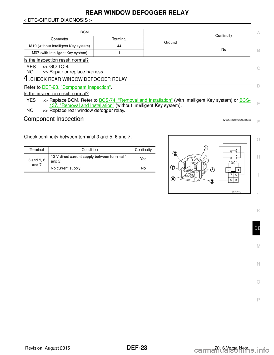
Component InspectionINFOID:0000000012431770
Check continuity between terminal 3 and 5, 6 and 7.
BCM
GroundContinuity
Connector Terminal
M19 (without Intelligent Key system) 44
No
M97 (with Intelligent Key system) 1
TerminalCondition Continuity
3 and 5, 6 and 7 12 V direct current supply between terminal 1
and 2
Ye s
No current supply No
SEF745U
Revision: August 2015 2016 Versa Note
cardiagn.com
Page 675 of 3641
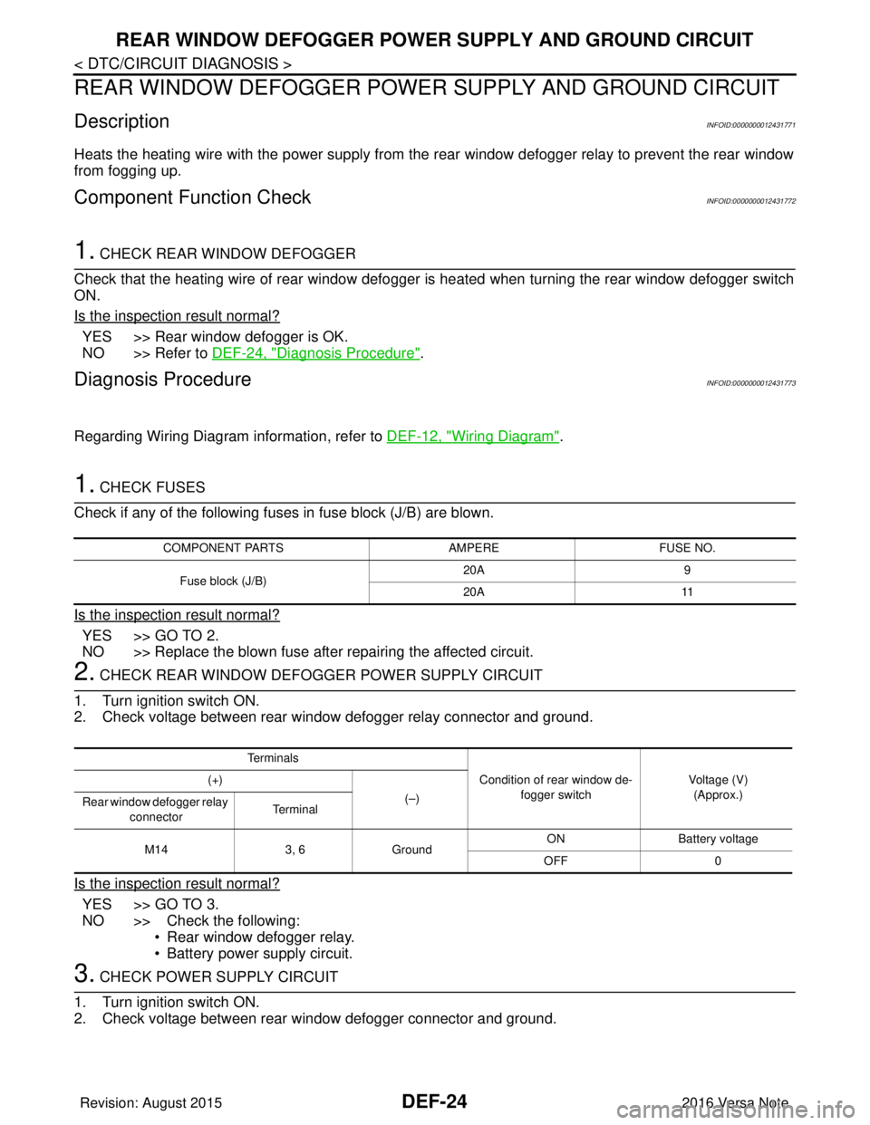
DEF-24
< DTC/CIRCUIT DIAGNOSIS >
REAR WINDOW DEFOGGER POWER SUPPLY AND GROUND CIRCUIT
REAR WINDOW DEFOGGER POWER SUPPLY AND GROUND CIRCUIT
DescriptionINFOID:0000000012431771
Heats the heating wire with the power supply from the rear window defogger relay to prevent the rear window
from fogging up.
Component Function CheckINFOID:0000000012431772
1. CHECK REAR WINDOW DEFOGGER
Check that the heating wire of rear window defogger is heated when turning the rear window defogger switch
ON.
Is the inspection result normal?
YES >> Rear window defogger is OK.
NO >> Refer to DEF-24, "
Diagnosis Procedure".
Diagnosis ProcedureINFOID:0000000012431773
Regarding Wiring Diagram information, refer to DEF-12, "Wiring Diagram".
1. CHECK FUSES
Check if any of the following fuses in fuse block (J/B) are blown.
Is the inspection result normal?
YES >> GO TO 2.
NO >> Replace the blown fuse after repairing the affected circuit.
2. CHECK REAR WINDOW DEFOGGER POWER SUPPLY CIRCUIT
1. Turn ignition switch ON.
2. Check voltage between rear window defogger relay connector and ground.
Is the inspection result normal?
YES >> GO TO 3.
NO >> Check the following: • Rear window defogger relay.
• Battery power supply circuit.
3. CHECK POWER SUPPLY CIRCUIT
1. Turn ignition switch ON.
2. Check voltage between rear window defogger connector and ground.
COMPONENT PARTS AMPEREFUSE NO.
Fuse block (J/B) 20A
9
20A 11
Te r m i n a l s
Condition of rear window de-fogger switch Voltage (V)
(Approx.)
(+)
(–)
Rear window defogger relay
connector Te r m i n a l
M14 3, 6Ground ON Battery
voltage
OFF 0
Revision: August 2015 2016 Versa Note
cardiagn.com
Page 676 of 3641
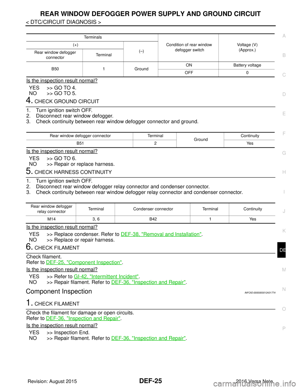
REAR WINDOW DEFOGGER POWER SUPPLY AND GROUND CIRCUIT
DEF-25
< DTC/CIRCUIT DIAGNOSIS >
C
D E
F
G H
I
J
K
M A
B
DEF
N
O P
Is the inspection result normal?
YES >> GO TO 4.
NO >> GO TO 5.
4. CHECK GROUND CIRCUIT
1. Turn ignition switch OFF.
2. Disconnect rear window defogger.
3. Check continuity between rear window defogger connector and ground.
Is the inspection result normal?
YES >> GO TO 6.
NO >> Repair or replace harness.
5. CHECK HARNESS CONTINUITY
1. Turn ignition switch OFF.
2. Disconnect rear window defogger re lay connector and condenser connector.
3. Check continuity between rear window defogger relay connector and condenser connector.
Is the inspection result normal?
YES >> Replace condenser. Refer to DEF-38, "Removal and Installation".
NO >> Replace or repair harness.
6. CHECK FILAMENT
Check filament.
Refer to DEF-25, "
Component Inspection".
Is the inspection result normal?
YES >> Refer to GI-42, "Intermittent Incident".
NO >> Repair filament. Refer to DEF-36, "
Inspection and Repair".
Component InspectionINFOID:0000000012431774
1. CHECK FILAMENT
Check the filament for damage or open circuits.
Refer to DEF-36, "
Inspection and Repair".
Is the inspection result normal?
YES >> Inspection End.
NO >> Repair filament. Refer to DEF-36, "
Inspection and Repair".
Te r m i n a l s
Condition of rear window defogger switch Voltage (V)
(Approx.)
(+)
(–)
Rear window defogger
connector Te r m i n a l
B50 1Ground ON
Battery voltage
OFF 0
Rear window defogger connector Terminal
Ground Continuity
B51 2 Yes
Rear window defogger
relay connector Terminal
Condenser connector TerminalContinuity
M14 3, 6 B42 1Yes
Revision: August 2015 2016 Versa Note
cardiagn.com
Page 677 of 3641
DEF-26
< DTC/CIRCUIT DIAGNOSIS >
DRIVER SIDE DOOR MIRROR DEFOGGER
DRIVER SIDE DOOR MIRROR DEFOGGER
DescriptionINFOID:0000000012431775
Heats the heating wire with the power supply from the rear window defogger relay to prevent the door mirror
from fogging up.
Component Function CheckINFOID:0000000012431776
1. CHECK DOOR MIRROR DEFOGGER LH
Check that heating wire of door mirror defogger LH is heated when turning the rear window defogger switch
ON.
Is the inspection result normal?
YES >> Door mirror defogger is OK.
NO >> Refer to DEF-26, "
Diagnosis Procedure".
Diagnosis ProcedureINFOID:0000000012431777
Regarding Wiring Diagram information, refer to DEF-12, "Wiring Diagram".
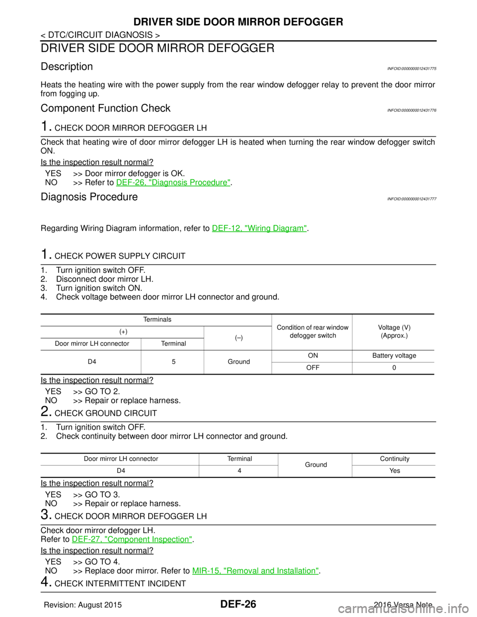
1. CHECK POWER SUPPLY CIRCUIT
1. Turn ignition switch OFF.
2. Disconnect door mirror LH.
3. Turn ignition switch ON.
4. Check voltage between door mirror LH connector and ground.
Is the inspection result normal?
YES >> GO TO 2.
NO >> Repair or replace harness.
2. CHECK GROUND CIRCUIT
1. Turn ignition switch OFF.
2. Check continuity between door mirror LH connector and ground.
Is the inspection result normal?
YES >> GO TO 3.
NO >> Repair or replace harness.
3. CHECK DOOR MIRROR DEFOGGER LH
Check door mirror defogger LH.
Refer to DEF-27, "
Component Inspection".
Is the inspection result normal?
YES >> GO TO 4.
NO >> Replace door mirror. Refer to MIR-15, "
Removal and Installation".
4. CHECK INTERMITTENT INCIDENT
Te r m i n a l s
Condition of rear window
defogger switch Voltage (V)
(Approx.)
(+)
(–)
Door mirror LH connector Terminal
D4 5Ground ON
Battery voltage
OFF 0
Door mirror LH connector Terminal
GroundContinuity
D4 4 Yes
Revision: August 2015 2016 Versa Note
cardiagn.com
Page 678 of 3641
DRIVER SIDE DOOR MIRROR DEFOGGER
DEF-27
< DTC/CIRCUIT DIAGNOSIS >
C
D E
F
G H
I
J
K
M A
B
DEF
N
O P
Check intermittent incident.
Refer to GI-42, "
Intermittent Incident".
Is the inspection result normal?
YES >> Check the following. • Battery power supply circuit.
• Fuse block (J/B).
NO >> Repair or replace the malfunctioning parts.
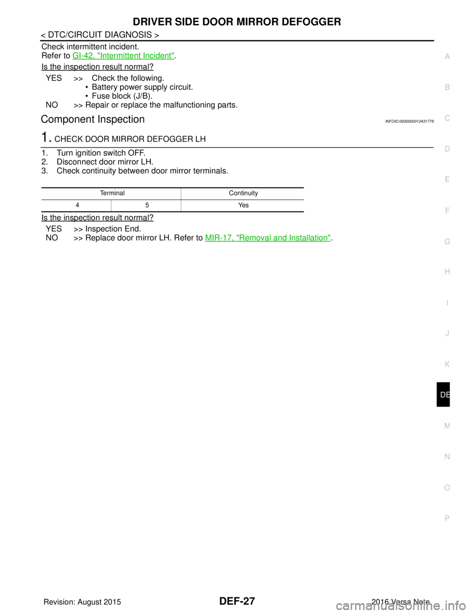
Component InspectionINFOID:0000000012431778
1. CHECK DOOR MIRROR DEFOGGER LH
1. Turn ignition switch OFF.
2. Disconnect door mirror LH.
3. Check continuity between door mirror terminals.
Is the inspection result normal?
YES >> Inspection End.
NO >> Replace door mirror LH. Refer to MIR-17, "
Removal and Installation".
Terminal Continuity
45 Y es
Revision: August 2015 2016 Versa Note
cardiagn.com
Page 679 of 3641
DEF-28
< DTC/CIRCUIT DIAGNOSIS >
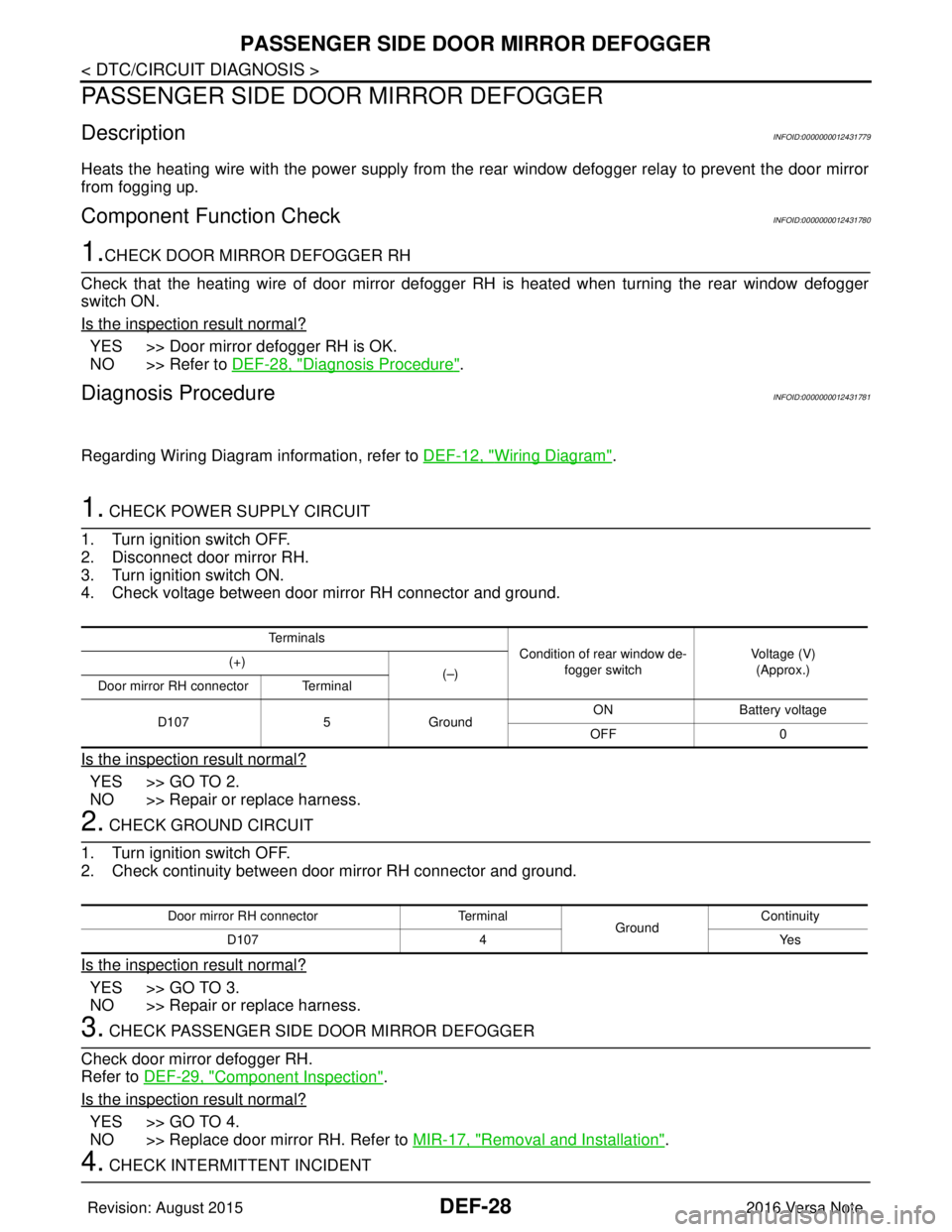
PASSENGER SIDE DOOR MIRROR DEFOGGER
PASSENGER SIDE DOOR MIRROR DEFOGGER
DescriptionINFOID:0000000012431779
Heats the heating wire with the power supply from the rear window defogger relay to prevent the door mirror
from fogging up.
Component Function CheckINFOID:0000000012431780
1.CHECK DOOR MIRROR DEFOGGER RH
Check that the heating wire of door mirror defogger RH is heated when turning the rear window defogger
switch ON.
Is the inspection result normal?
YES >> Door mirror defogger RH is OK.
NO >> Refer to DEF-28, "
Diagnosis Procedure".
Diagnosis ProcedureINFOID:0000000012431781
Regarding Wiring Diagram information, refer to DEF-12, "Wiring Diagram".
1. CHECK POWER SUPPLY CIRCUIT
1. Turn ignition switch OFF.
2. Disconnect door mirror RH.
3. Turn ignition switch ON.
4. Check voltage between door mirror RH connector and ground.
Is the inspection result normal?
YES >> GO TO 2.
NO >> Repair or replace harness.
2. CHECK GROUND CIRCUIT
1. Turn ignition switch OFF.
2. Check continuity between door mirror RH connector and ground.
Is the inspection result normal?
YES >> GO TO 3.
NO >> Repair or replace harness.
3. CHECK PASSENGER SIDE DOOR MIRROR DEFOGGER
Check door mirror defogger RH.
Refer to DEF-29, "
Component Inspection".
Is the inspection result normal?
YES >> GO TO 4.
NO >> Replace door mirror RH. Refer to MIR-17, "
Removal and Installation".
4. CHECK INTERMITTENT INCIDENT
Te r m i n a l s
Condition of rear window de-
fogger switch Voltage (V)
(Approx.)
(+)
(–)
Door mirror RH connector Terminal
D107 5Ground ON
Battery voltage
OFF 0
Door mirror RH connector Terminal
GroundContinuity
D107 4 Yes
Revision: August 2015 2016 Versa Note
cardiagn.com
Page 680 of 3641
PASSENGER SIDE DOOR MIRROR DEFOGGERDEF-29
< DTC/CIRCUIT DIAGNOSIS >
C
DE
F
G H
I
J
K
M A
B
DEF
N
O P
Check intermittent incident.
Refer to GI-42, "
Intermittent Incident".
Is the inspection result normal?
YES >> Check the following. • Battery power supply circuit.
• Fuse block (J/B).
NO >> Repair or replace the malfunctioning parts.
Component InspectionINFOID:0000000012431782
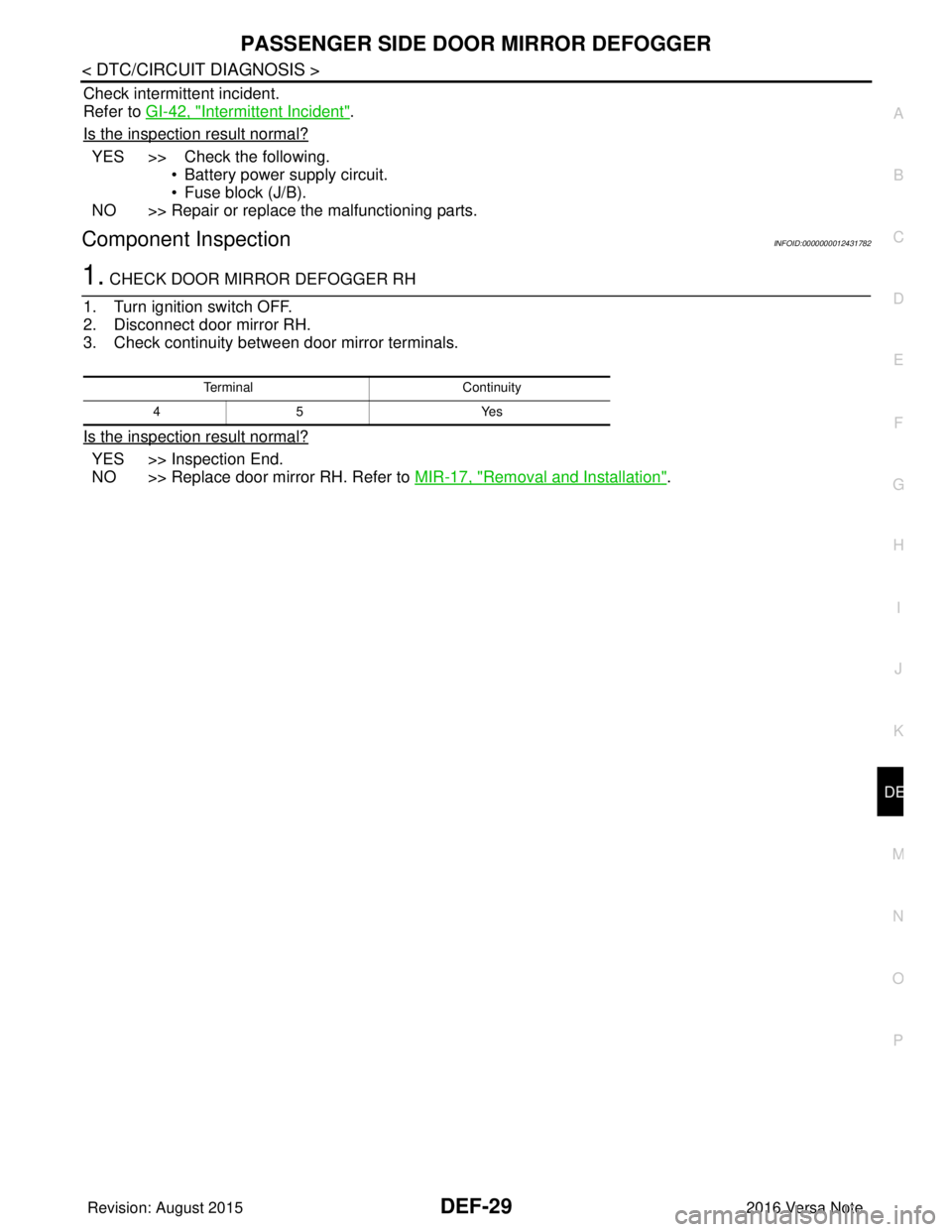
1. CHECK DOOR MIRROR DEFOGGER RH
1. Turn ignition switch OFF.
2. Disconnect door mirror RH.
3. Check continuity between door mirror terminals.
Is the inspection result normal?
YES >> Inspection End.
NO >> Replace door mirror RH. Refer to MIR-17, "
Removal and Installation".
Terminal Continuity
45 Y es
Revision: August 2015 2016 Versa Note
cardiagn.com