NISSAN PATROL 1998 Y61 / 5.G Electrical System Workshop Manual
PATROL 1998 Y61 / 5.G
NISSAN
NISSAN
https://www.carmanualsonline.info/img/5/616/w960_616-0.png
NISSAN PATROL 1998 Y61 / 5.G Electrical System Workshop Manual
Trending: clock, Wiring diagrams, indicator, brake sensor, check engine, Section GI, Headlamp
Page 181 of 326
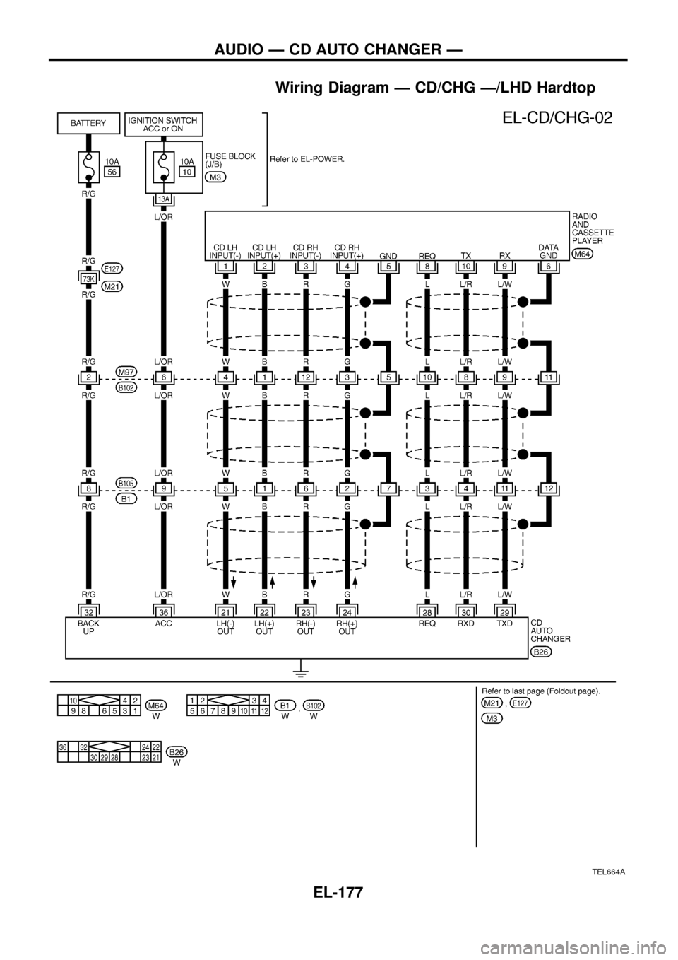
Wiring Diagram Ð CD/CHG Ð/LHD Hardtop
TEL664A
AUDIO Ð CD AUTO CHANGER Ð
EL-177
Page 182 of 326
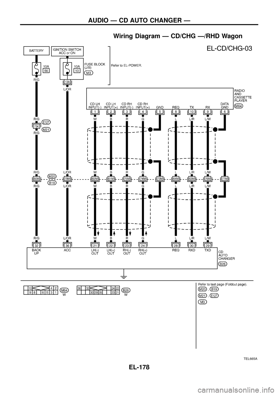
Wiring Diagram Ð CD/CHG Ð/RHD Wagon
TEL665A
AUDIO Ð CD AUTO CHANGER Ð
EL-178
Page 183 of 326
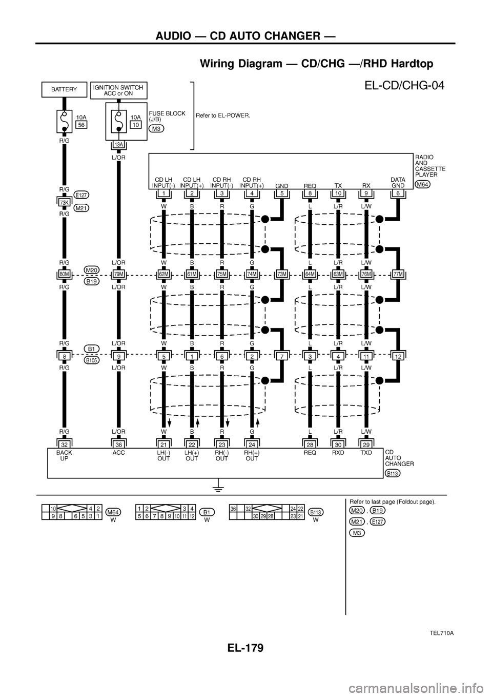
Wiring Diagram Ð CD/CHG Ð/RHD Hardtop
TEL710A
AUDIO Ð CD AUTO CHANGER Ð
EL-179
Page 184 of 326
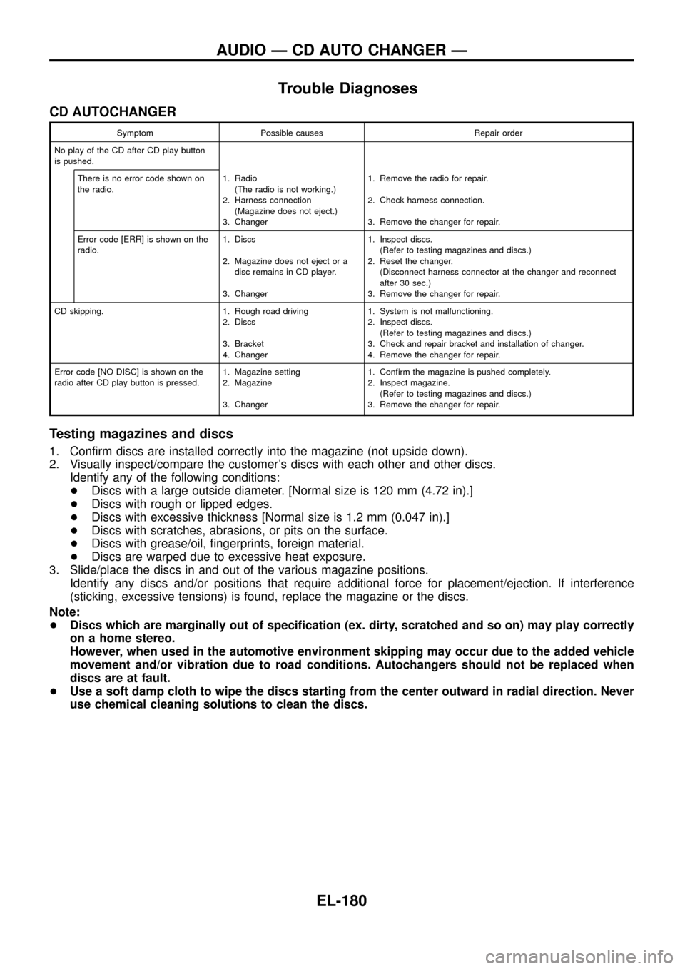
Trouble Diagnoses
CD AUTOCHANGER
Symptom Possible causes Repair order
No play of the CD after CD play button
is pushed.
There is no error code shown on
the radio.1. Radio
(The radio is not working.)
2. Harness connection
(Magazine does not eject.)
3. Changer1. Remove the radio for repair.
2. Check harness connection.
3. Remove the changer for repair.
Error code [ERR] is shown on the
radio.1. Discs
2. Magazine does not eject or a
disc remains in CD player.
3. Changer1. Inspect discs.
(Refer to testing magazines and discs.)
2. Reset the changer.
(Disconnect harness connector at the changer and reconnect
after 30 sec.)
3. Remove the changer for repair.
CD skipping. 1. Rough road driving
2. Discs
3. Bracket
4. Changer1. System is not malfunctioning.
2. Inspect discs.
(Refer to testing magazines and discs.)
3. Check and repair bracket and installation of changer.
4. Remove the changer for repair.
Error code [NO DISC] is shown on the
radio after CD play button is pressed.1. Magazine setting
2. Magazine
3. Changer1. Con®rm the magazine is pushed completely.
2. Inspect magazine.
(Refer to testing magazines and discs.)
3. Remove the changer for repair.
Testing magazines and discs
1. Con®rm discs are installed correctly into the magazine (not upside down).
2. Visually inspect/compare the customer's discs with each other and other discs.
Identify any of the following conditions:
+Discs with a large outside diameter. [Normal size is 120 mm (4.72 in).]
+Discs with rough or lipped edges.
+Discs with excessive thickness [Normal size is 1.2 mm (0.047 in).]
+Discs with scratches, abrasions, or pits on the surface.
+Discs with grease/oil, ®ngerprints, foreign material.
+Discs are warped due to excessive heat exposure.
3. Slide/place the discs in and out of the various magazine positions.
Identify any discs and/or positions that require additional force for placement/ejection. If interference
(sticking, excessive tensions) is found, replace the magazine or the discs.
Note:
+Discs which are marginally out of speci®cation (ex. dirty, scratched and so on) may play correctly
on a home stereo.
However, when used in the automotive environment skipping may occur due to the added vehicle
movement and/or vibration due to road conditions. Autochangers should not be replaced when
discs are at fault.
+Use a soft damp cloth to wipe the discs starting from the center outward in radial direction. Never
use chemical cleaning solutions to clean the discs.
AUDIO Ð CD AUTO CHANGER Ð
EL-180
Page 185 of 326
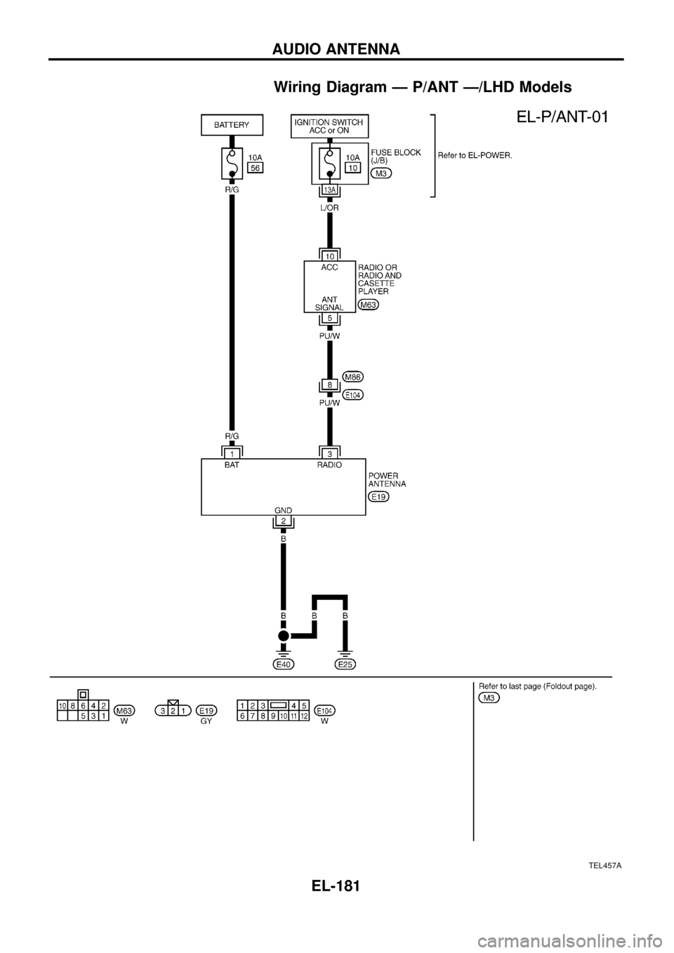
Wiring Diagram Ð P/ANT Ð/LHD Models
TEL457A
AUDIO ANTENNA
EL-181
Page 186 of 326
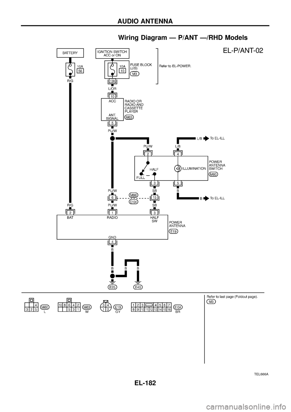
Wiring Diagram Ð P/ANT Ð/RHD Models
TEL666A
AUDIO ANTENNA
EL-182
Page 187 of 326
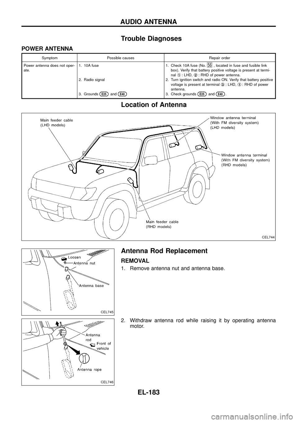
Trouble Diagnoses
POWER ANTENNA
Symptom Possible causes Repair order
Power antenna does not oper-
ate.1. 10A fuse
2. Radio signal
3. Grounds
E25andE40
1. Check 10A fuse (No.56, located in fuse and fusible link
box). Verify that battery positive voltage is present at termi-
nalj
1: LHD,j2: RHD of power antenna.
2. Turn ignition switch and radio ON. Verify that battery positive
voltage is present at terminalj
3: LHD,j1: RHD of power
antenna.
3. Check grounds
E25andE40.
Location of Antenna
Antenna Rod Replacement
REMOVAL
1. Remove antenna nut and antenna base.
2. Withdraw antenna rod while raising it by operating antenna
motor.
CEL744
CEL745
CEL746
AUDIO ANTENNA
EL-183
Page 188 of 326
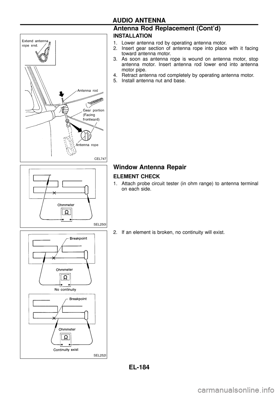
INSTALLATION
1. Lower antenna rod by operating antenna motor.
2. Insert gear section of antenna rope into place with it facing
toward antenna motor.
3. As soon as antenna rope is wound on antenna motor, stop
antenna motor. Insert antenna rod lower end into antenna
motor pipe.
4. Retract antenna rod completely by operating antenna motor.
5. Install antenna nut and base.
Window Antenna Repair
ELEMENT CHECK
1. Attach probe circuit tester (in ohm range) to antenna terminal
on each side.
2. If an element is broken, no continuity will exist.
CEL747
SEL250I
SEL252I
AUDIO ANTENNA
Antenna Rod Replacement (Cont'd)
EL-184
Page 189 of 326
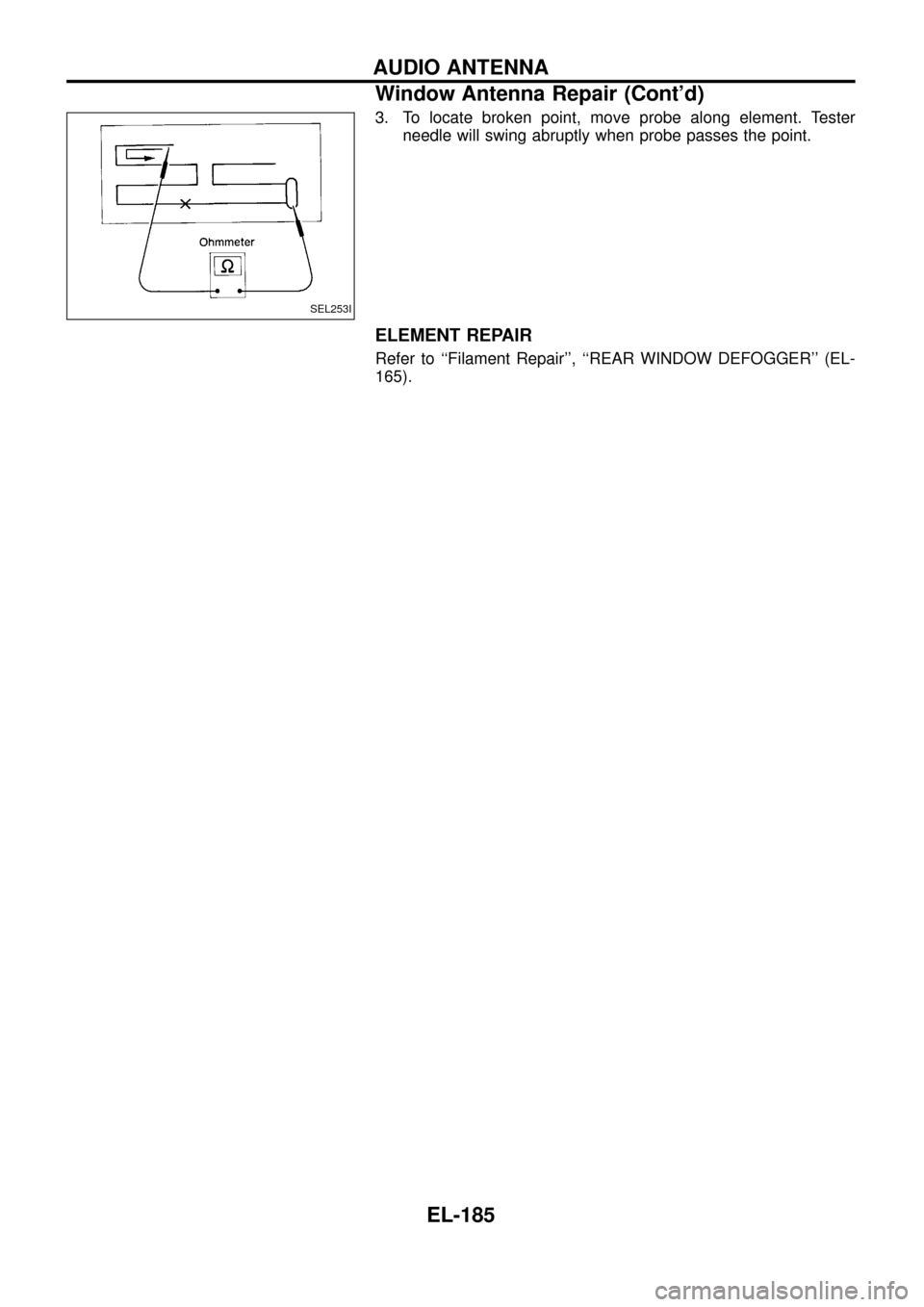
3. To locate broken point, move probe along element. Tester
needle will swing abruptly when probe passes the point.
ELEMENT REPAIR
Refer to ``Filament Repair'', ``REAR WINDOW DEFOGGER'' (EL-
165).
SEL253I
AUDIO ANTENNA
Window Antenna Repair (Cont'd)
EL-185
Page 190 of 326
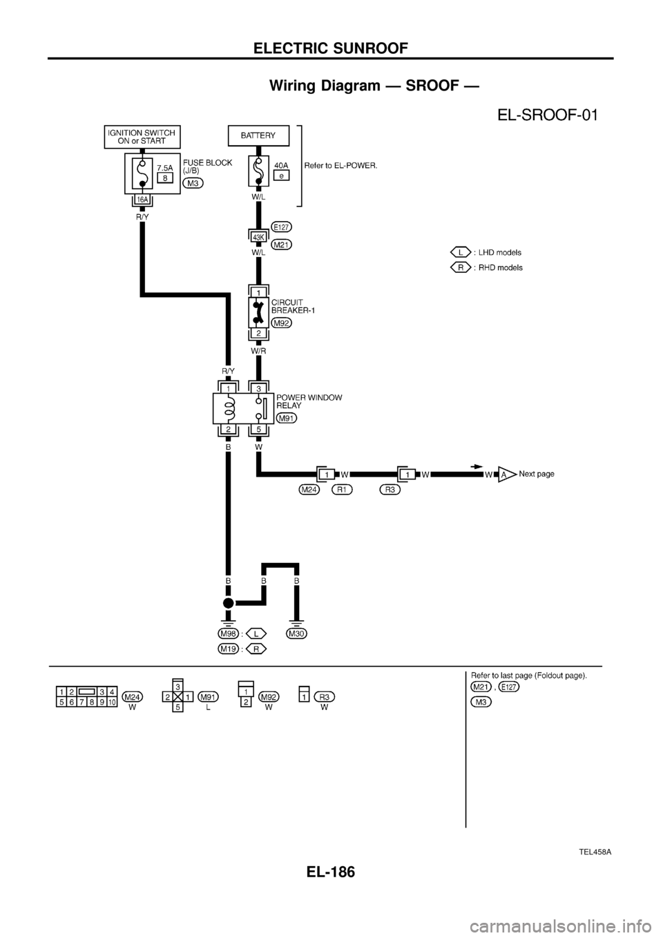
Wiring Diagram Ð SROOF Ð
TEL458A
ELECTRIC SUNROOF
EL-186
Trending: oil type, Fuel solenoid, Lock, Wiring diagram engin, Accelerator, Ec section, ECO mode
